Giant Magneto Resistive Position Sensor
Version 1.0
GMR S6
Data Sheet
1
1999-04-01
Data Sheet
This angle sensor is based on the brand new Giant Magneto Resistive (GMR)
technology. It is outstanding for the huge tolerances it offers to the user in
assembly.
x
new type
Type
Marking
Ordering Code
x
GMR S6
S
Q62705-K5003
Features
∑ GMR sensor in SMD package
∑ Sensitive to the direction, not
to the intensity of the magnetic
field
∑ Constant
T
C
of basic
resistance
R
and magneto
resistance
R
Typical Applications
∑ Rotation sensing with large air
gaps according to sketch
below
∑ Angle encoders
∑ Contactless potentiometers
Pin Configuration
5 (= 2), 6
supply voltage
1, 3, 4
not connected
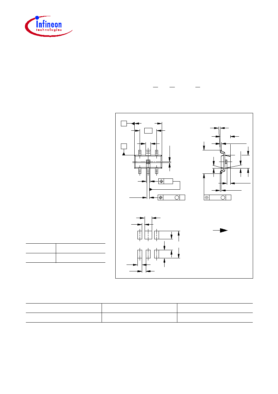
Dimensions in mm
Internal magnetization is in direction of the longest side of the
housing.
0.3
-0.05
+0.1
+0.1
-0.05
0.6
6
4
1
B
A
0.25
M
B
0.08 ... 0.15
1.1 max
2∞ ... 30∞
2.6 max
10∞ max
10∞ max
0.1 max
A
M
0.20
2.9
±0.1
1.3
±0.1
2
3
5
1.9
GPW06957
0.2
±0.15
0.35
±0.3
0.1
1.2
3
0.8
0.3
0.5
0.45
0.9
Reflow soldering
Directions of internal
magnetization
GMR S6
Data Sheet
2
1999-04-01
The GMR S6 is an angle sensor based on sputtered metallic multilayer technology. The
outstanding feature of this magnetic sensor is the fact that it is sensitive to the
orientation of the magnetic field and not to its intensity as long as the field is in a range
between 5 ... 15 kA/m. This means the signal output of this sensor is independent
of the sensor position relative to the magnet in lateral, axial or rotational direction
in the range of several millimeters. Optimum results are achieved by using magnetic
targets like permanent magnets or magnetic pole-wheels. There is no need for a
biasing magnet! Due to the linear change of both, basic and field dependent part of the
resistance vs. temperature, simple and efficient electronic compensation of
T
C
(
R
,
R
) is
possible.
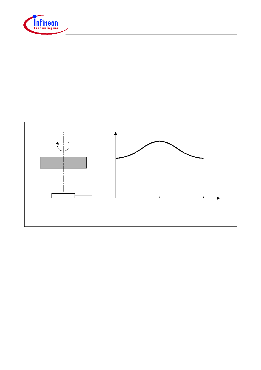
OHS00375
Resistance
0∞
180∞
360∞
Rotating
Magnet
GMR Sensor
Output signal vs orientation of magnet
R = R
0
+ 0.5
R *
)
(1-cos
N
S
*
Principle of operation
Angle

GMR S6
Data Sheet
3
1999-04-01
Application Hints
The application mode of the GMR position sensor is preferably as a bridge or halfbridge
circuit. In every case this type of circuit compensates for the
T
C
of the resistance value
R
0
. To compensate for the
T
C
of the GMR effect
R
/
R
0
, if there is the necessity, is left to
the application circuit and can be done for example with a NIC circuit. When operated
over a complete 360
∞
turn, a total signal of
20 mV/V is achieved at 25
∞
C with a
halfbridge. The output signal is doubled when a fullbridge circuit is used. In the case of
linear position sensing, the electrical circuit remains unchanged.
Maximum Ratings
Parameter
Symbol
Value
Unit
Operating temperature
T
A
≠ 40 ... + 150
∞
C
Storage temperature
T
stg
≠ 50 ... + 150
∞
C
Supply current
I
1
5
mA
Thermal conductivity
G
thC
A
G
thC
C
> 2.2
> 5
mW/K
mW/K
Magnetic field
1)
H
rot
< 15
kA/m
1)
larger fields may reduce the magnetoresistive effect irreversibly
Characteristics (
T
A
= 25
∞
C)
Parameter
Symbol
Value
Unit
Nominal supply current
I
1N
4
mA
Basic resistance
R
0
> 700
Magnetoresistive effect
H
rot
= 5 ... 15 kA/m
R
/
R
0
4
%
Temperature coefficient of
basic resistance
TC
R0
+ 0.09 ... + 0.12
%/K
Temperature coefficient of
magnetoresistance
TC
R
≠ 0.12 ... ≠ 0.09
%/K
Temperature coefficient of
magnetoresistive effect
TC
R/R0
≠ 0.27 ... ≠ 0.23
%/K
Hysteresis at
H
rot
= 10 kA/m
Hys
< 2
degrees