 | –≠–ª–µ–∫—Ç—Ä–æ–Ω–Ω—ã–π –∫–æ–º–ø–æ–Ω–µ–Ω—Ç: ICE2A365 | –°–∫–∞—á–∞—Ç—å:  PDF PDF  ZIP ZIP |

C o o l S E T TM - F 2
I C E 2 A 1 6 5 / 2 6 5 / 3 6 5
I C E 2 A 1 8 0 / 2 8 0
O f f - L i n e S M P S C u r r e n t M o d e
C o n t r o l l e r w i t h i n t e g r a t e d 6 5 0 V /
8 0 0 V C o o l M O S TM
N e v e r s t o p t h i n k i n g .
P o w e r M a n a g em e n t & S u p p l y
D a t a s h e e t , V e r s i o n 3 . 0 , S e p t e m b e r 2 0 0 1

Edition 2001-09-19
Published by Infineon Technologies AG,
St.-Martin-Strasse 53,
D-81541 M¸nchen
©
Infineon Technologies AG 1999.
All Rights Reserved.
Attention please!
The information herein is given to describe certain components and shall not be considered as warranted char-
acteristics.
Terms of delivery and rights to technical change reserved.
We hereby disclaim any and all warranties, including but not limited to warranties of non-infringement, regarding
circuits, descriptions and charts stated herein.
Infineon Technologies is an approved CECC manufacturer.
Information
For further information on technology, delivery terms and conditions and prices please contact your nearest Infin-
eon Technologies Office in Germany or our Infineon Technologies Representatives worldwide (see address list).
Warnings
Due to technical requirements components may contain dangerous substances. For information on the types in
question please contact your nearest Infineon Technologies Office.
Infineon Technologies Components may only be used in life-support devices or systems with the express written
approval of Infineon Technologies, if a failure of such components can reasonably be expected to cause the failure
of that life-support device or system, or to affect the safety or effectiveness of that device or system. Life support
devices or systems are intended to be implanted in the human body, or to support and/or maintain and sustain
and/or protect human life. If they fail, it is reasonable to assume that the health of the user or other persons may
be endangered.
For questions on technology, delivery and prices please contact the Infineon Technologies Offices in Germany or
the Infineon Technologies Companies and Representatives worldwide: see our webpage at http://
www.infineon.com
CoolMOSTM, CoolSETTM are trademarks of Infineon Technologies AG.
CoolSETTM-F2
Revision History:
2001-09-19
Datasheet
Previous Version:
First One
Page
Subjects (major changes since last revision)
We Listen to Your Comments
Any information within this document that you feel is wrong, unclear or missing at all?
Your feedback will help us to continuously improve the quality of this document.
Please send your proposal (including a reference to this document) to:
mcdocu.comments@infineon.com
Datasheet
3
September 2001
Type
Ordering Code
Package
U
DS
F
OSC
R
DSon
1)
1)
typ @ T=25∞C
230VAC ±15%
2)
2)
Maximum power rating at Ta=75∞C, Tj=125∞C and with copper area on PCB = 6cm≤,
85-265 VAC
2)
ICE2A165
Q67040-S4426
P-DIP-8-6
650V
100kHz
3.0
31W
18W
ICE2A265
Q67040-S4414
P-DIP-8-6
650V
100kHz
0.9
52W
32W
ICE2A365
Q67040-S4415
P-DIP-8-6
650V
100kHz
0.45
67W
45W
ICE2A180
ES Samples available P-DIP-8-6
800V
100kHz
3.0
31W
18W
ICE2A280
Q67040-S4416
P-DIP-8-6
800V
100kHz
0.8
54W
34W
CoolSETTM-F2
ICE2A165/265/365
ICE2A180/280
P-DIP-8-6
C
Soft Start
C
VCC
R
Start-up
VCC
-
Converter
DC Output
+
CoolSETTM-F2
Snubber
Power
Management
Protection Unit
Soft-Start Control
PWM Controller
Current Mode
FB
85 ... 270 VAC
Drain
Feedback
Feedback
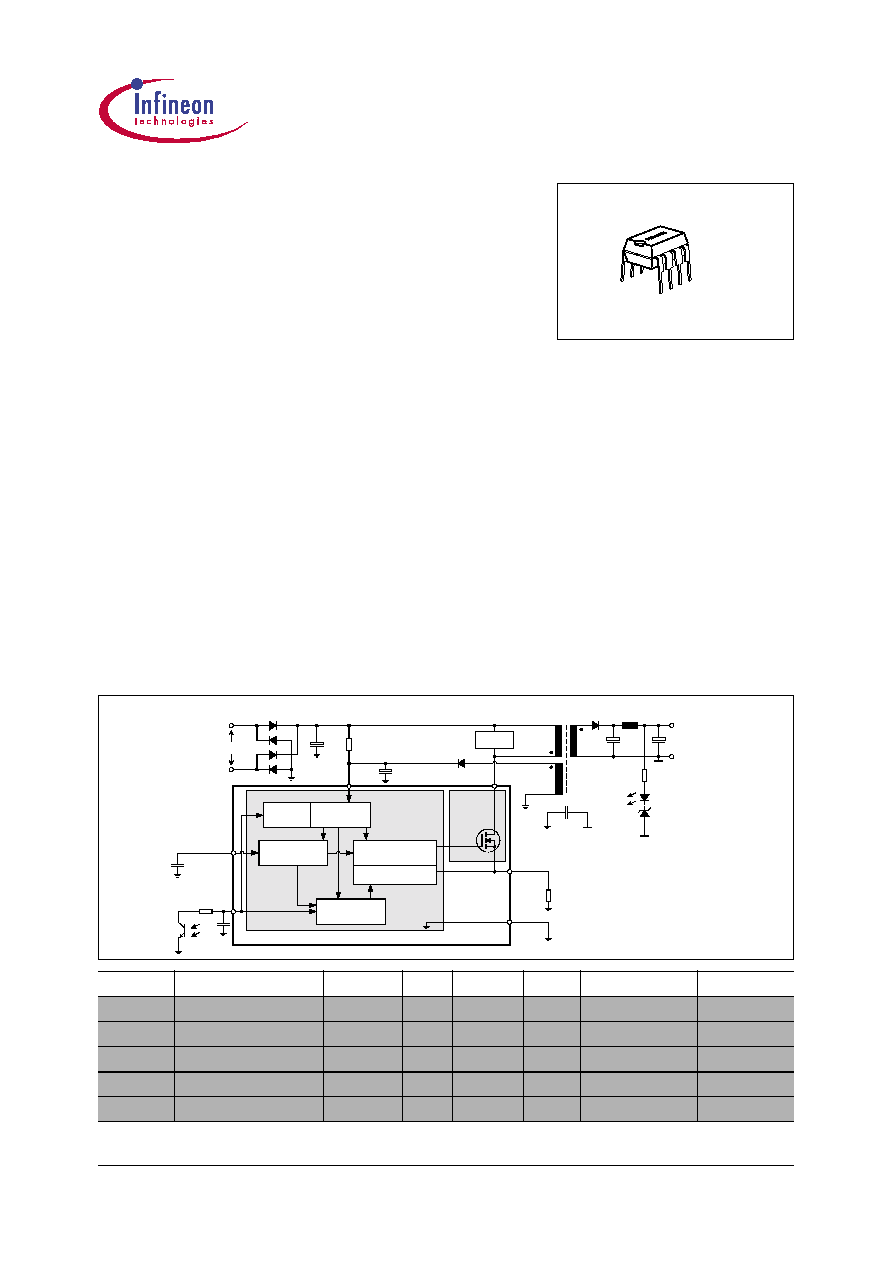
Typical Application
CoolMOSTM
PWM-Controller
Low Power
StandBy
Precise Low Tolerance
Peak Current Limitation
R
Sense
Isense
GND
SoftS
Off-Line SMPS Current Mode Controller
with integrated 650V/800V CoolMOSTM
Product Highlights
∑ Best of Class in DIP8 Package
∑ No Heatsink required
∑ Lowest Standby Power Dissipation
∑ Enhanced Protection Functions all
with Auto Restart Mode
Features
∑
650V/800V Avalanche Rugged CoolMOSTM
∑
Only few external Components required
∑
Input Undervoltage Lockout
∑
100kHz Switching Frequency
∑
Max Duty Cycle 72%
∑
Low Power Standby Mode to meet European
Commission Requirements
∑
Thermal Shut Down with Auto Restart
∑
Overload and Open Loop Protection
∑
Overvoltage Protection during Auto Restart
∑
Adjustable Peak Current Limitation via
External Resistor
∑
Overall Tolerance of Current Limiting
<
±5%
∑
Internal Leading Edge Blanking
∑
User defined Soft Start
∑
Soft Switching for Low EMI
Description
The second generation COOLSETTM-F2 provides several
special enhancements to satisfy the needs for low power
standby and protection features. In standby mode
frequency reduction is used to lower the power
consumption and support a stable output voltage in this
mode. The frequency reduction is limited to 21.5 kHz to
avoid audible noise. In case of failure modes like open loop,
overvoltage or overload due to short circuit the device
switches in Auto Restart Mode which is controlled by the
internal protection unit. By means of the internal precise
peak current limitation the dimension of the transformer and
the secondary diode can be lower which leads to more cost
efficiency.

CoolSETTM-F2
ICE2A165/265/365
ICE2A180/280
Table of Contents
Page
Datasheet
4
September 2001
1
Pin Configuration and Functionality . . . . . . . . . . . . . . . . . . . . . . . . . . . . .5
1.1
Pin Configuration . . . . . . . . . . . . . . . . . . . . . . . . . . . . . . . . . . . . . . . . . . . . . .5
1.2
Pin Functionality . . . . . . . . . . . . . . . . . . . . . . . . . . . . . . . . . . . . . . . . . . . . . .5
2
Representative Blockdiagram . . . . . . . . . . . . . . . . . . . . . . . . . . . . . . . . . .6
3
Functional Description . . . . . . . . . . . . . . . . . . . . . . . . . . . . . . . . . . . . . . . .7
3.1
Power Management . . . . . . . . . . . . . . . . . . . . . . . . . . . . . . . . . . . . . . . . . . . .7
3.2
Improved Current Mode . . . . . . . . . . . . . . . . . . . . . . . . . . . . . . . . . . . . . . . . .7
3.2.1
PWM-OP . . . . . . . . . . . . . . . . . . . . . . . . . . . . . . . . . . . . . . . . . . . . . . . . . .8
3.2.2
PWM-Comparator . . . . . . . . . . . . . . . . . . . . . . . . . . . . . . . . . . . . . . . . . . .8
3.3
Soft-Start . . . . . . . . . . . . . . . . . . . . . . . . . . . . . . . . . . . . . . . . . . . . . . . . . . . .9
3.4
Oscillator and Frequency Reduction . . . . . . . . . . . . . . . . . . . . . . . . . . . . . .10
3.4.1
Oscillator . . . . . . . . . . . . . . . . . . . . . . . . . . . . . . . . . . . . . . . . . . . . . . . . .10
3.4.2
Frequency Reduction . . . . . . . . . . . . . . . . . . . . . . . . . . . . . . . . . . . . . . . .10
3.5
Current Limiting . . . . . . . . . . . . . . . . . . . . . . . . . . . . . . . . . . . . . . . . . . . . . .10
3.5.1
Leading Edge Blanking . . . . . . . . . . . . . . . . . . . . . . . . . . . . . . . . . . . . . .10
3.5.2
Propagation Delay Compensation . . . . . . . . . . . . . . . . . . . . . . . . . . . . . .11
3.6
PWM-Latch . . . . . . . . . . . . . . . . . . . . . . . . . . . . . . . . . . . . . . . . . . . . . . . . .11
3.7
Driver . . . . . . . . . . . . . . . . . . . . . . . . . . . . . . . . . . . . . . . . . . . . . . . . . . . . . .11
3.8
Protection Unit (Auto Restart Mode) . . . . . . . . . . . . . . . . . . . . . . . . . . . . . .12
3.8.1
Overload & Open loop with normal load . . . . . . . . . . . . . . . . . . . . . . . . .12
3.8.2
Overvoltage due to open loop with no load . . . . . . . . . . . . . . . . . . . . . . .13
3.8.3
Thermal Shut Down . . . . . . . . . . . . . . . . . . . . . . . . . . . . . . . . . . . . . . . . .13
4
Electrical Characteristics . . . . . . . . . . . . . . . . . . . . . . . . . . . . . . . . . . . . .14
4.1
Absolute Maximum Ratings . . . . . . . . . . . . . . . . . . . . . . . . . . . . . . . . . . . . .14
4.2
Operating Range . . . . . . . . . . . . . . . . . . . . . . . . . . . . . . . . . . . . . . . . . . . . .15
4.3
Characteristics . . . . . . . . . . . . . . . . . . . . . . . . . . . . . . . . . . . . . . . . . . . . . . .15
4.3.1
Supply Section . . . . . . . . . . . . . . . . . . . . . . . . . . . . . . . . . . . . . . . . . . . . .15
4.3.2
Internal Voltage Reference . . . . . . . . . . . . . . . . . . . . . . . . . . . . . . . . . . .15
4.3.3
Control Section . . . . . . . . . . . . . . . . . . . . . . . . . . . . . . . . . . . . . . . . . . . .16
4.3.4
Protection Unit . . . . . . . . . . . . . . . . . . . . . . . . . . . . . . . . . . . . . . . . . . . . .16
4.3.5
Current Limiting . . . . . . . . . . . . . . . . . . . . . . . . . . . . . . . . . . . . . . . . . . . .16
4.3.6
CoolMOSTM Section . . . . . . . . . . . . . . . . . . . . . . . . . . . . . . . . . . . . . . . . .17
5
Typical Performance Characteristics . . . . . . . . . . . . . . . . . . . . . . . . . . .18
6
Outline Dimension . . . . . . . . . . . . . . . . . . . . . . . . . . . . . . . . . . . . . . . . . . .22

Datasheet
5
September 2001
CoolSETTM-F2
ICE2A165/265/365
ICE2A180/280
Pin Configuration and Functionality
1
Pin Configuration and Functionality
1.1
Pin Configuration
Figure 1
Pin Configuration (top view)
1.2
Pin Functionality
SoftS (Soft Start & Auto Restart Control)
This pin combines the function of Soft Start in case of
Start Up and Auto Restart Mode and the controlling of
the Auto Restart Mode in case of an error detection.
FB (Feedback)
The information about the regulation is provided by the
FB Pin to the internal Protection Unit and to the internal
PWM-Comparator to control the duty cycle.
Isense (Current Sense)
The Current Sense pin senses the voltage developed
on the series resistor inserted in the source of the
integrated CoolMOSTM. When Isense reaches the
internal threshold of the Current Limit Comparator, the
Driver output is disabled. By this means the Over
Current Detection is realized.
Furthermore the current information is provided for the
PWM-Comparator to realize the Current Mode.
Drain (Drain of integrated CoolMOSTM)
Pin Drain is the connection to the Drain of the internal
CoolMOS
TM
.
VCC (Power supply)
This pin is the positiv supply of the IC. The operating
range is between 8.5V and 21V.
To provide overvoltage protection the driver gets
disabled when the voltage becomes higher than 16.5V
during Start Up Phase.
GND (Ground)
This pin is the ground of the primary side of the SMPS.
Pin
Symbol
Function
1
SoftS
Soft-Start
2
FB
Feedback
3
Isense
Controller Current Sense Input,
CoolMOSTM Source Output
4
Drain
650V
1)
/800V CoolMOSTM Drain
1)
at T
j
= 110∞C
5
Drain
650V
2)
/800V CoolMOSTM Drain
2)
at T
j
= 110∞C
6
N.C
Not connected
7
VCC
Controller Supply Voltage
8
GND
Controller Ground
1
6
7
8
4
3
2
5
VCC
FB
Isense
Drain
SoftS
N.C
GND
Drain
Package P-DIP-8-6