Data Sheet
1
1999-04-01
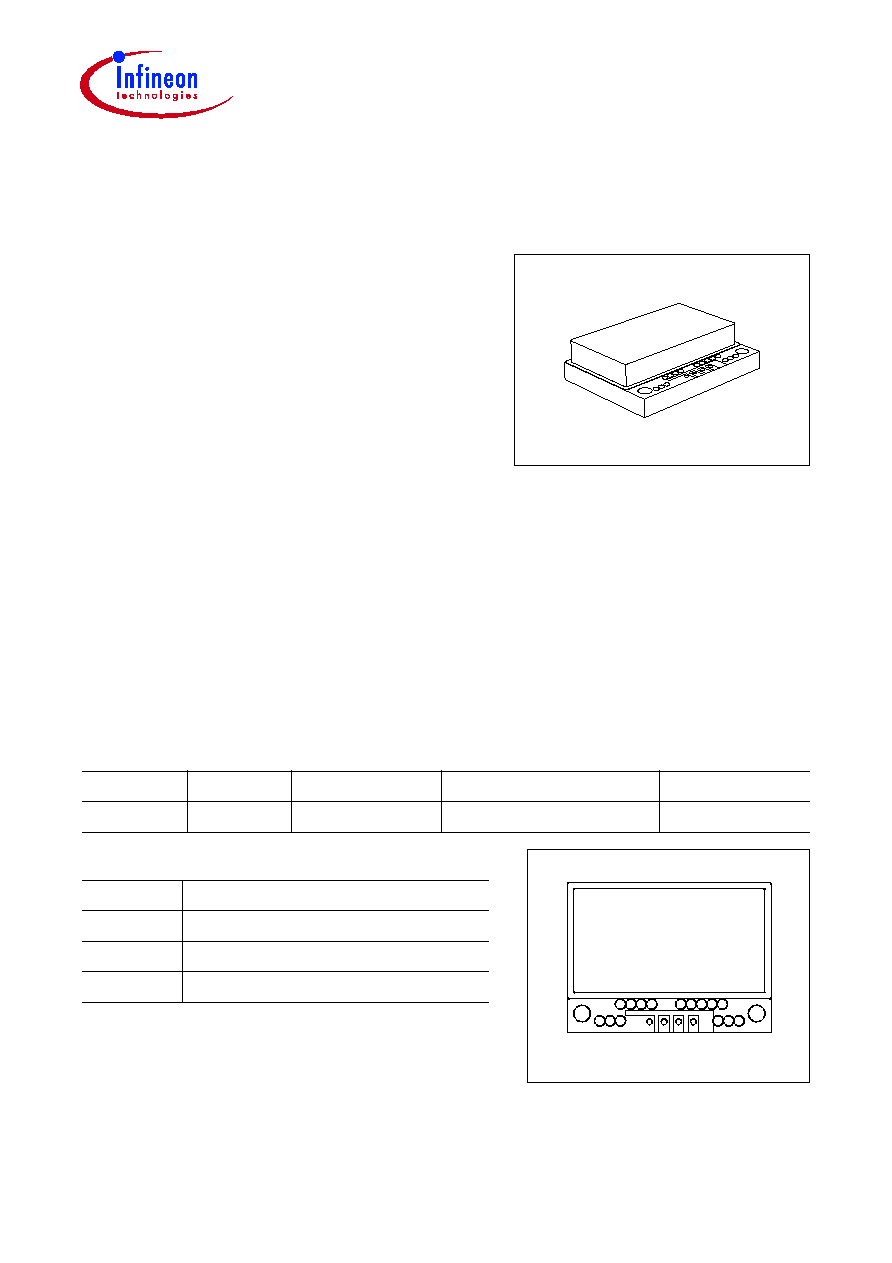
Microwave Motion Sensor
KMY 24
Description
The KMY 24 is a microwave rader motion sensor
based on the Doppler effect. It transmits a low
energy microwave radiation at 2.45 GHz which is
reflected by objects. If the object is moving relative
to the sensor, a Doppler shift occurs. The shifted
wave is mixed with the original wave in two mixers,
resulting in two output voltage signals. The phase
shift between these two signals is negative or
positive depending on whether the target is
approaching or receding from the detector.
Features
∑ High sensitivity
∑ Dual Mixers enabling direction detecting
∑ High reliability
∑ Low power consumption
∑ Low harmonic emission
∑ Small size
∑ Light weight
∑ Low cost
Notes:
1. Solder pads must not be perforated, as this will damage,
and may destroy the multilayer PC Board.
2. Regulations on the use of High frequency devices.
The use of high frequency devices is regulated in most
countries and certain frequencies can be subject to restrictions. The use of the KMY 24 should be clarified with
the respective authorities in each country to ensure compliance with the prevalent legislation.
Typ
Marking
Ordering Code
Operating Frequency
License No.
KMY 24
KMY 24
Q62702-R323
2.45 GHz
BZT G127520H
Pin Configuration
1
-
V
S
(GND)
2
V
D1
(output voltage D1)
3
V
D2
(output voltage D2)
4
+
V
S
EHA07260
2 3 4
1
SIEMENS
KMY 24

KMY 24
Data Sheet
2
1999-04-01
1) The amplitude of the signal depends on the object size and its distance from the detector. Measurements taken
with 5 cm high, cylindrical metallic objects, moving in circles at a distance of 1 m for example, give signal
amplitudes of typically
V
D1
= 40 mV.
Absolute Maximum Ratings
Parameter
Symbol
Limit Values
Unit
Operating temperature range
T
op
-
20
...
+ 60
∞
C
Storage temperature range
T
stg
-
30
...
+ 80
∞
C
Supply voltage
V
S
15.6
V
Electrical Characteristics
at
T
A
= 25
∞
C
Parameter
Symbol
Limit Values
Unit
min.
typ.
max.
Supply voltage
V
S
10.8
12
15.6
V
Operating frequency
f
o
2.40
2.45
2.48
GHz
Operating current
I
op
-
23
-
mA
Detecting range
1)
r
op
-
5
...
8
-
m
Amplitude of signal 1
V
D1
-
1)
-
mV
Quotient of amplitude of 1 and 2
V
D1
/
V
D2
-
2
-
Phase difference
2
-
1
-
40
...
120
-
Degrees
Equivalent isotropic radiated power at
f
o
EIRP
-
8
-
dBm
KMY 24
Data Sheet
3
1999-04-01
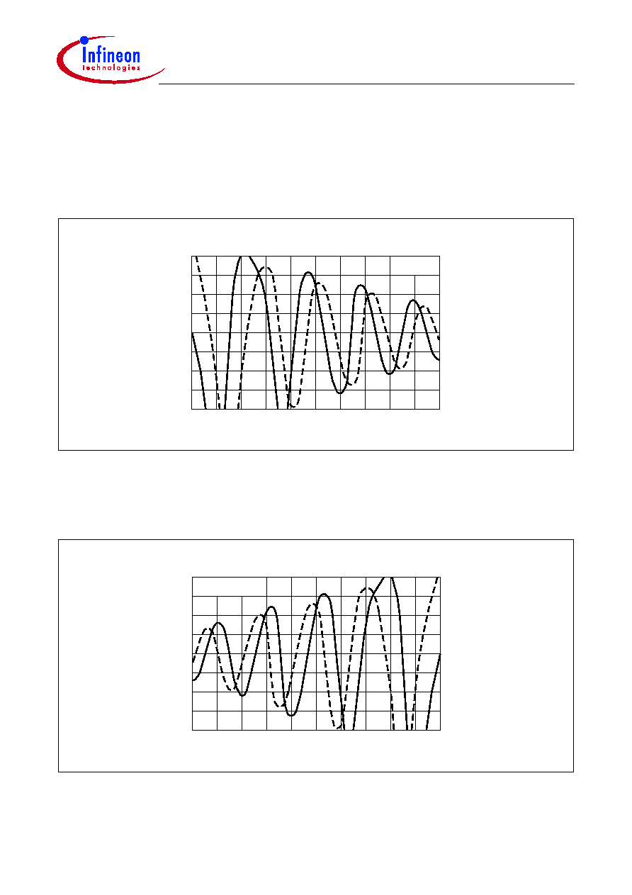
Output Signal
The phase difference between
V
D2
and
V
D1
is positive, if the target is receding from the
detector.
The phase difference between
V
D2
and
V
D1
is negative, if the target is approaching the
detector.
1
2
≠
(
)
0
EHA07261
Receding
Ch1 10 mV
Ch2
10 mV
100
M
ms
V
D2
D1
V
1
2
≠
(
)
0
EHA07262
Approaching
Ch1 10 mV
Ch2
10 mV
100
M
ms
V
D2
D1
V

KMY 24
Data Sheet
4
1999-04-01
Typical Radiation Pattern
The diagram shows the typical radiation pattern in the x-z- and y-z-planes. The
z-direction is perpendicular to the patch antenna, x shows the longer and y the shorter
side of the rectangular antenna.
Package Outline
EHA07263
90
60
30
0
0 dB
dB
-10
-20 dB
Sorts of Packing
Package outlines for tubes, trays etc. are contained in our
Data Book "Package Information".
Dimensions in mm
EHA07466
Marking
3
¯3.2
0.8
2.5
15.2
3
26
38
5
5.5
19.9
Special Package