 | –≠–ª–µ–∫—Ç—Ä–æ–Ω–Ω—ã–π –∫–æ–º–ø–æ–Ω–µ–Ω—Ç: SPFBFT302 | –°–∫–∞—á–∞—Ç—å:  PDF PDF  ZIP ZIP |
S P F B F T 3 0 2
BFT3 02 data sheet_04_nov_02
page
1
from 13
04-nov-02
Optical Bidirectional Transceiver for byteflight SPF BFT3 02
Data Sheet
Safety hints
Application of new chip technologies leads to increasing optical efficiency and
growing and higher levels of optical performance.
We therefore recommend that the current versions of the IEC 825-1 and EN 60825-1
standards are taken into account right from the outset, i.e. at the equipment
development stage, and that suitable protection facilities are provided.
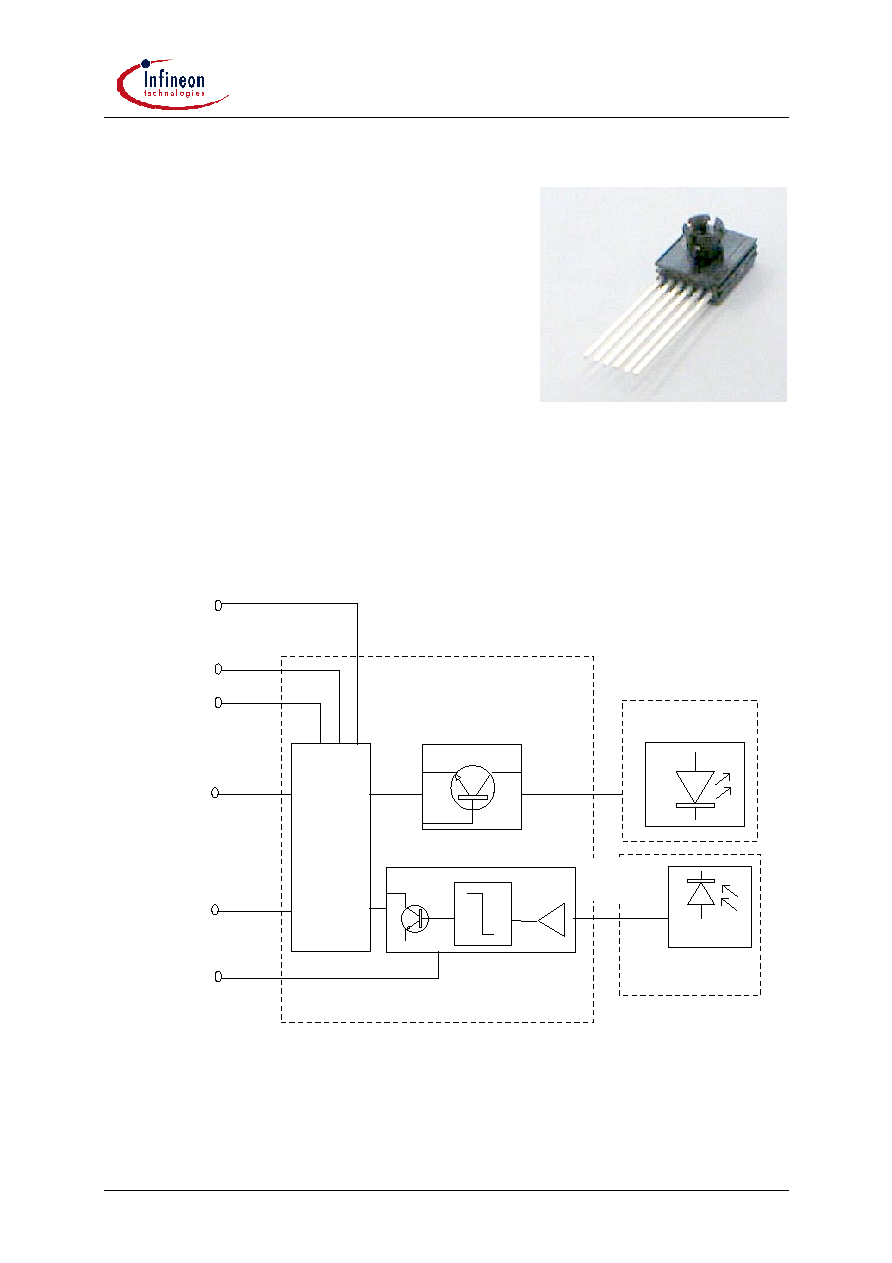
1. Short description of complete functional unit
The device consists of a LED mounted on a large area photodiode for bidirectional optical transmission
in half duplex mode. LED and photodiode are driven by the multifunction IC E100.34C1 from ELMOS.
The transmitting and receiving functional units with ELMOS-IC E100.34C1 may be split into the
following blocks:
Tr
an
sm
itter
/R
ec
e
i
v
e
r
G
a
t
e
LED Driver
LED
Receivingamplifier
Photodiode
Transmitter
LEDO
LEDI
DO
DI
VDD1
ALARM
GND
VDD2
Fig. 1: Basic functional units of SPF BFT3 02
PDI
S P F B F T 3 0 2
BFT3 02 data sheet_04_nov_02
page
2
from 13
04-nov-02
Features
∑
Optical transmitter and receiver for maximum datarate 10 Mbaud (half duplex burst mode)
∑
Transmitter: LED with 650 nm for working in low attenuation range of PMMA fiber
∑
Receiver: Photodiode with preamp, digitizer with DC elimination circuit (tracked decision
threshold), Sleep - and Wake-up-Function, output stage (electrical output driver)
∑
Built in transmitter and receiver gate for half duplex mode (mutual blocking of transmitter and
receiver)
∑
Operation at 5V or 8V-11V power supply voltage
∑
Built in pulse width detection for indicating Sync, Alarm and continuous light on (integrated time
basis to differentiate and evaluate Sync, Alarm and Continuous Light
conditions Alarm output)
∑
Diagnose function for photocurrent
∑
Mechanical assembly: 6 Pin CAI package for easy coupling of POF (plastic optical fiber) with insert
2. Basic Specification
2.1 Absolute maximum ratings
Note:
Usage of the device out of the maximum ranges given in this chapter may damage the
transceiver!
Parameter
Symbol
min
max
Unit
Storage Temperature Range
T
STG
- 40
100
∞C
Operating Temperature Range
T
A
- 40
85
∞C
Soldering Temperature
(
10 seconds more than 4,5 mm apart
from package; details see app. note)
T
S
235
∞C
Maximum optical input power onto
receiver
P
optmaxRec
-
5
mW
Parameter
Symbol
min
max
Unit
Voltages against GND:
Supply Voltage
V
DD1
- 0,3
16
V
Signal Input DI
V
inm
- 0,3
6
V
Signal Output DO
V
outm
- 0,3
6
V
Output ALARM
V
outm
- 0,3
16
V
Output DO shortening time *
1)
t
sDO
-
1
s
Current into Alarm-pin (active Alarm state) I
Alarm
-
10
mA
*1) The electrical output DO may be shortened for a short period of time t
sDO
. During this time the
voltage at DO has to be within 0V <= V
DO
<= 5V
S P F B F T 3 0 2
BFT3 02 data sheet_04_nov_02
page
3
from 13
04-nov-02
2.2 Operating Conditions
All the data in this specification refer to the following operating conditions unless otherwise stated.
Parameter
Symbol
min
typ
max
Unit
Supply Voltage
V
DD1
4,75
5
5,5
V
Supply Voltage, optional
V
DD1
7,8
9
11,3
V
Datarate
DBR
10
Mbit/s
Duration of one bit
t
bit
100
ns
Duration of sync pulse
t
sync
2,9
3
3,1
µs
Duration of Alarm pulse
t
alarm
1,9
2
2,1
µs
Bright phase Wake-up Impulse
t
plwu
6
6,4
6,8
µ
s
Dark phase Wake-up Impulse
t
pdwu
6
6,4
6,8
µ
s
2.3 Interface Description
Pinning
Pin
Pin-Name
Description
1
DI
Signal Input/Data In
2
ALARM
Alarm out (open drain)
3
VDD1
positive power supply
4
VDD2
internally regulated power supply
5
GND
Ground
6
DO
Signal Output/Data out (push-pull)
Optical Signals
Name
Description
Light on
Light off
LEDO
optical Signal, emitted of Transceiver
1
0
PDI (=LEDI)
optical Signal, received of Transceiver
1
0
Note:
Transmitter and Receiver invert the signals, which means that
-
in standard transmitting mode: low level (0V) at DI causes the illumination of the LED (LEDO ,,1" =
light on) and vice versa,
-
in standard receiving mode: no light onto the Photodiode (PDI ,,0" = light off) causes output of 5V at
DO and vice versa.

S P F B F T 3 0 2
BFT3 02 data sheet_04_nov_02
page
4
from 13
04-nov-02
3. Detailed Specification
3.1 Optical Function Transmitter
Electrical and Optical Characteristics of LED and Driver:
Parameter
Conditions
Symbol
Min.
Typ.
Max.
Unit
Data Rate
*2)
10
Mbit/s
Optical Output Power
(peak)
1mm Standard
PMMA fiber 30cm
optimum coupling,
0h, T
A
=25∞C
P
opt25
274
(-5,6)
450
(-3,5)
740
(-1,3)
µW
(dBm)
Optical Output Power
(peak)
1mm Standard
PMMA fiber 30cm
optimum coupling,
0h, -40∞C....+85∞C
P
opt-40∞ -
+85∞
166
(-7,8)
1000
(0)
µW
(dBm)
Optical Output Power
(peak)
1mm Standard
PMMA fiber 30cm
optimum coupling,
over lifetime,
-40∞C.....+85∞C
P
opt-40∞-
+85∞/life
132
(-8,8)
1250
(+1,0)
µW
(dBm)
Optical Rise Time,
Optical Fall Time
10% to 90%
t
r
, t
f
35
ns
Pulse Width Distortion,
Optical Signal
PWD
Trans
-5
+5
ns
Peak emission
wavelength
+25∞C
Peak
640
650
660
nm
Peak emission
wavelength
-40∞C.....+85∞C
Peak
630
650
670
nm
*2) Limitation due to electrical power dissipation: Duty cycle for > 1s: 10 %, Duty cycle for < 1 s: 50 %
3.2 Optical Function Receiver
Electrical and optical characteristics of receiving photodiode with amplifier in high speed data receiving
(active) mode:
Parameter
Conditions
Symbol
Min.
Typ.
Max.
Unit
Data Rate
10
Mbit/s
Pulse Width Distortion
*3)
PWD
Rec
- 25
+ 25
ns
Pulse Width Start pulse
P
min
PW
Start
500
600
660
ns
Maximum receiveable power Signal at DO
according
PWD
Rec
P
max
*4)
800
(-1,0)
µW
(dBm)
Minimum receiveable power
Signal at DO
according
PWD
Rec
P
min
*4)
20
(-17)
µW
(dBm)
Recovery time after last
transmitted bit
t
rec
1,1
µs
*3) The Pulse Width Distortion is tested with a worst case pattern at a certain single high pulse P1 of
the standard pattern some bits after starting the burst.
*4) All Optical Power Data are peak values.

S P F B F T 3 0 2
BFT3 02 data sheet_04_nov_02
page
5
from 13
04-nov-02
3.3 Static Characteristics
Parameter
Condition
Symbol
min
typ
max
Unit
Peak Supply Current in active
mode (see 2.1,
*2)
)
LED on
I
dda
50
mA
Supply current in active mode
LED off
I
dda
10
mA
Supply current in stand-by mode 10ms after
t
sleepmax
I
Stby
30
45
µA
Low Level Input Voltage DI
V
IL
0
0,8
V
High Level Input Voltage DI
V
ICH
2
6
V
Low Level Output Voltage DO
I = 1mA
V
OLD
0
0,4
V
High Level Output Voltage DO
I = -1mA
V
OHD
3,7
5
V
Low Level Output Voltage
ALARM
I = 5mA
V
OLA
0
0,4
V
Input Capacitance at DI
C
DI
5
pF
Optical Power Threshold for
photo current diagnosis
P
DIAG
-
15
(-18,2)
20
(-17)
µ
W
(dBm)
Internally regulated voltage
V
DD1
=7,8 -
11,3V
V
DD2
4,6
5,5
V
3.4 Dynamic Characteristics
Parameter
Condition
Symbol
min
typ
max
Unit
Signal delay (LEDI -> DO)
t
del-DO
200
ns
Rise and fall time on DO
CL= 30pF
t
r
, t
f
30
ns
Wake-up time *5)
t
wu
10
ms
Sleep-in time *6)
t
sl
10
20
ms
Continuous light on time *7)
t
cl
10
11,4
15
µs
Locking time with el. signal *8)
t
locke
700
1100
ns
Locking time with opt. signal *8)
t
locko
300
700
ns
Duration of diagnosis impulse
t
pdi
80
100
120
ns
Pause before diagnosis impulse
t
wdi
1,17
1,3
µ
s
Delay diagnosis impulse
t
ddi
10
220
ns
*5) Time between the first optical wake-up pattern and switching into active mode
*6) Time between transmitting last bit and switching into sleep mode
*7) Duration for detection of continuous light
*8) After recognizing High levels on the internal data path at the lock switch input (see block wiring
diagram), the other relevant channel is blocked for this period.