Data Sheet
1
2001-06-01
Medium Power
1300 nm FP Laser
STM51004x
STM51005x
Fiber Optics
Features
∑ Designed for applications in fiber optic networks
∑ Laser Diode with Multi-Quantum Well structure
∑ Suitable for bit rates up to 1 Gbit/s
∑ Ternary Photodiode at rear mirror for monitoring
and control of radiant power
∑ Hermetically sealed subcomponents,
similar to TO 46
∑ SM pigtail with optional connector

STM51004x
STM51005x
Pin Configuration and Flange
Data Sheet
2
2001-06-01
Pin Configuration and Flange
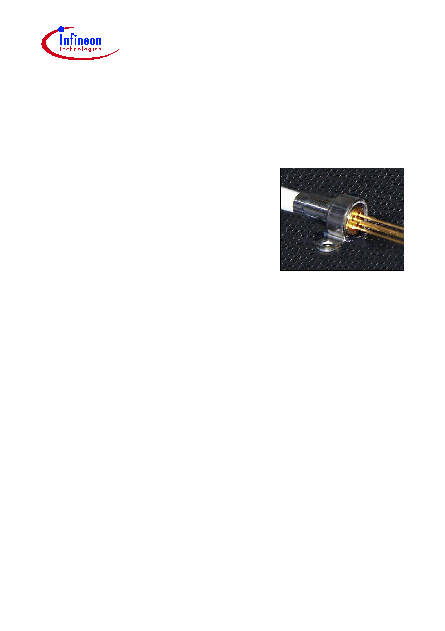
Figure 1
Transmitter
Available Pinnings with and without Flange
Type
Transmitter
Flange
STM51004x
1
without
STM51005x 1
with
1
2
3
4
2.54 mm
Transmitter (bottom view)
1
4
2
3
MD
LD
Pinning 1

STM51004x
STM51005x
Description
Data Sheet
3
2001-06-01
Description
Differences between a Fabry-Perot and a DFB Laserdiode
A conventional laser consists of an amplifying medium and two end mirrors. The cavity
is longer than one wavelength, and a standing wave is created. The number n of half
wavelengths
is
. If L >>
then we speak of a Fabry-Perot Laser because the
laserdiode emits multi-longitudinal modes. Typically the laserdiode is 250 µm long. For
= 1310 nm/1550 nm n is about 350. Therefore for many neighboring wavelengths the
"standing wavelength" condition specified above is fulfilled. For a DFB-Laser a special
grating acts as a distributed filter allowing only one of the cavity's longitudinal modes to
propagate. This can be described with a reduced oscillator length which is in the range
of
. For such a reduced oscillator length the standing wavelength condition will be
fulfilled for n
2 what means for only one wavelength.
Figure 2
Fabry-Perot Laserdiode
n
2
L
---
◊
=
L
~
1
Wavelength
Intensity
0
0
1
2
3
4
5
4

STM51004x
STM51005x
Description
Data Sheet
4
2001-06-01
Figure 3
DFB Laserdiode
Regulatory Compliance
Feature
Standard
Comments
Electrostatic
Discharge (ESD) to the
Electrical Pins
MIL-STD 883D
Method 3015.7
Class 1 (<500 V)
Wavelength
Intensity
0
0
1
2
3
4
5
4

STM51004x
STM51005x
Technical Data
Data Sheet
5
2001-06-01
Technical Data
The electro-optical characteristics described in the following tables are only valid for use
within the specified maximum ratings or under the recommended operating conditions.
Absolute Maximum Ratings
Parameter
Symbol
Limit Values
Unit
min.
max.
Module
Operating temperature range at case
T
C
≠40
85
∞C
Storage temperature range
T
stg
≠40
85
Soldering temperature (
t
max
= 10 s,
2 mm distance from bottom edge of case)
T
S
260
Laser Diode
Direct forward current
I
F max
120
mA
Radiant power CW
P
F, rad
2
mW
Reverse Voltage
V
R
2
V
Monitor Diode
Reverse Voltage
V
R
10
V
Forward Current
I
F
2
mA
Transmitter Electro-Optical Characteristics
Parameter
Symbol
Limit Values
Unit
min.
typ.
max.
Optical output power
(maximum)
P
F, max
1.2
mW
Emission wavelength center of
range,
P
F
= 0.5
P
F, max.
trans
1280
1330
nm
Spectral width (RMS)
5
Temperature coefficient of
wavelength
TC
0.5
nm/K
Threshold current
(whole temperature range)
I
th
2
45
mA
Forward voltage,
P
F
= 0.5
P
F, max.
V
F
1.5
V
Radiant power at
I
th
P
th
40
µW