Data Sheet
1
2000-03-01
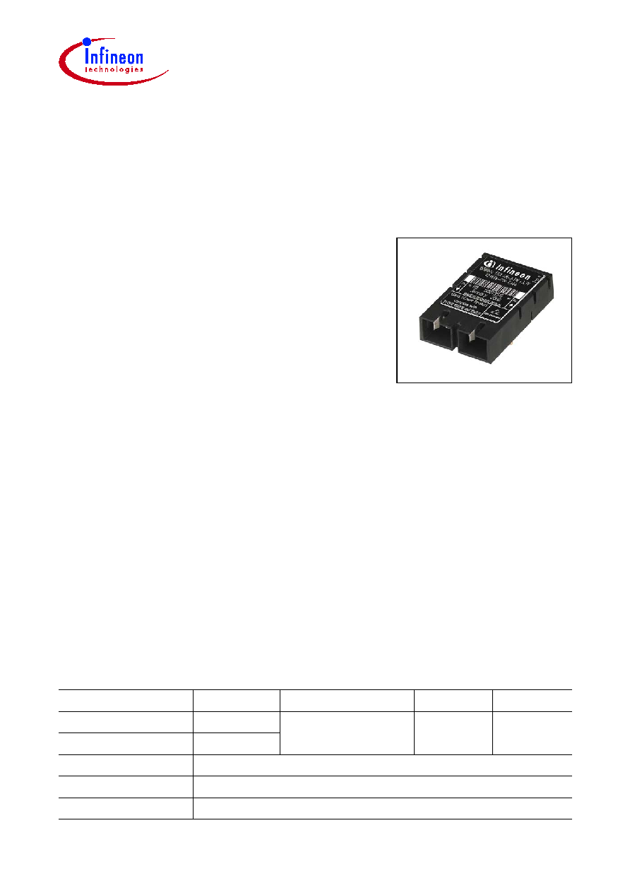
DC/DC (5 V/3.3 V) Single Mode 155 MBd
ATM/SDH/SONET 1x9 Long Haul Transceiver
V23826-C18-C64
V23826-C18-C364
Part Number
Voltage
Signal Detect
Input
Output
V23826-C18-C64
5 V
PECL
DC
DC
V23826-C18-C364
3.3 V
Add suffix to PIN
Shield options
-C3
Metallized cover, forward springs
-D3
Metallized cover, backward springs
Fiber Optics
Features
∑ Compliant with ATM, SONET OC-3, SDH STM-1
∑ Meets mezzanine standard height of 9.8 mm
∑ Compact integrated transceiver unit with
≠ MQW laser diode transmitter
≠ InGaAs PIN photodiode receiver
≠ Duplex SC receptacle
∑ Class 1 FDA and IEC laser safety compliant
∑ FDA Accession No. 9520890-20
∑ Single power supply (5 V or 3.3 V)
∑ Signal detect indicator
∑ PECL differential inputs and outputs
∑ Process plug included
∑ Input Signal Monitor
∑ Wave solderable and washable with process plug inserted
∑ Typical dynamic range of 36 dB
∑ Industry standard multisource 1x9 footprint
∑ For distances of up to 40 km on single mode fiber

V23826-C18-C64
V23826-C18-C364
Pin Configuration
Data Sheet
2
2000-03-01
Pin Configuration
Figure 1
Pin Description
Pin
No.
Symbol
Level/Logic
Function
Description
1
Rx
V
EE
Power Supply
Rx Ground
Negative power supply,
normally ground
2
RD
PECL Output
Rx Output Data
Receiver output data
3
RDn
Inverted receiver output data
4
SD
PECL Output
active high
Rx Signal
Detect
A high level on this output shows
that optical data is applied to the
optical input.
5
Rx
V
CC
Power Supply
Rx +3.3 V / 5 V
Positive power supply,
+3.3 V / 5 V
6
Tx
V
CC
Tx +3.3 V / 5 V
7
TDn
PECL Input
Tx Input Data
Inverted transmitter input data
8
TD
Transmitter input data
9
Tx
V
EE
Power Supply
Tx Ground
Negative power supply,
normally ground
S1/2
Mech. Support
Stud Pin
Not connected
1 2 3 4
5 6
7 8 9
Top View

V23826-C18-C64
V23826-C18-C364
Description
Data Sheet
3
2000-03-01
Description
The Infineon single mode ATM transceiver complies with the ATM Forum's Network
Compatible ATM for Local Network Applications document and ANSI's Broadband
ISDN - Customer Installation Interfaces, Physical Media Dependent Specification,
T1.646-1995, Bellcore-SONET OC-3/LR-1 and ITU-T G.957 STM-1/L.1.1.
ATM was developed to facilitate solutions in multimedia applications and real time
transmission. The data rate is scalable, and the ATM protocol is the basis of the
broadband public networks being standardized in the International Telecommunications
Union (ITU), the former International Telegraph and Telephone Consultative Committee
(CCITT). ATM can also be used in local private applications.
The Infineon single mode ATM long haul transceiver is a single unit comprised of a
transmitter, a receiver, and an SC receptacle. This design frees the customer from many
alignment and PC board layout concerns. The module is designed for low cost WAN
applications. It can be used as the network end device interface in workstations, servers,
and storage devices, and in a broad range of network devices such as bridges, routers,
intelligent hubs, and wide area ATM switches.
This transceiver operates at 155.520 Mbit/s from a single power supply (+5 V or +3.3 V).
The differential data inputs and outputs are PECL compatible.
Functional Description
This transceiver is designed to transmit serial data via single mode cable.
Figure 2
Functional Diagram
Laser
Driver
Power
Control
Receiver
o/e
o/e
Laser
e/o
RX Coupling Unit
TD
TD
RD
RD
SD
Laser Coupling Unit
Single Mode Fiber
LEN
Monitor
Signal Monitor and
Automatic Shut-Down
ISM

V23826-C18-C64
V23826-C18-C364
Description
Data Sheet
4
2000-03-01
The transmitter converts electrical PECL compatible serial data (TD and TDnot) into
optical serial data. It contains a laser driver circuit that drives the modulation and bias
current of the laser diode. The currents are controlled by a power control circuit to
guarantee constant output power of the laser over temperature and aging.
The power control uses the output of the monitor PIN diode (mechanically built into the
laser coupling unit) as a controlling signal, to prevent the laser power from exceeding the
operating limits.
This transceiver contains an Input Signal Monitor (ISM), that switches the optical power
off if a continuously low level is applied at Data Input.
The receiver component converts the optical serial data into PECL compatible electrical
data (RD and RDnot). The Signal Detect (SD, active high) shows whether optical data is
present
1)
.
This module is a Class 1 laser product, due to an integrated automatic shutdown circuit
that disables the laser when it detects transmitter failures.
Single fault condition is ensured by means of an integrated automatic shutdown circuit
that disables the laser when it detects transmitter failures. A reset is only possible by
turning the power off, and then on again.
The transceiver contains a supervisory circuit to monitor the power supply. This circuit
makes an internal reset signal whenever the supply voltage drops below the reset
threshold. It keeps the reset signal active for at least 15 milliseconds after the voltage
has risen above the reset threshold. During this time the laser is inactive.
1)
We recommend to switch off the transmitter supply (
V
CC
- Tx) if no transmitter input data is applied.

V23826-C18-C64
V23826-C18-C364
Description
Data Sheet
5
2000-03-01
Regulatory Compliance
Feature
Standard
Comments
Electrostatic Discharge
(ESD) to the Electrical
Pins
MIL-STD 883C
Method 3015.4
Class 1 (>1000 V)
Immunity:
Electrostatic Discharge
(ESD) to the Duplex SC
Receptacle
EN 61000-4-2
IEC 61000-4-2
Discharges of ±15 kV with an air
discharge probe on the receptacle
cause no damage.
Immunity:
Radio Frequency
Electromagnetic Field
EN 61000-4-3
IEC 61000-4-3
With a field strength of 10 V/m rms,
noise frequency ranges from 3 MHz
to 1 GHz. No effect on transceiver
performance between the
specification limits.
Emission:
Electromagnetic
Interference (EMI)
FCC Class B
EN 55022 Class B
CISPR 22
Noise frequency range:
30 MHz to 6 GHz, margins depend
on PCB layout and chassis design.