Data Sheet
1
2000-03-09
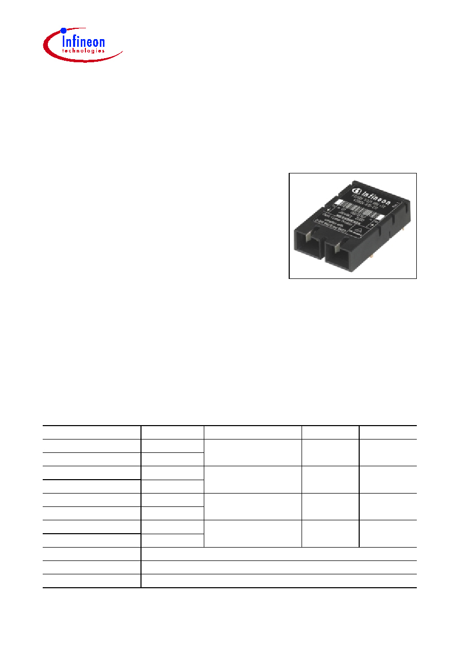
Single Mode 1300 nm 1.0625 GBd
Fibre Channel 1.3 Gigabit Ethernet
1x9 Transceiver
V23826-K15-Cxx/Cxxx
Part Number
Voltage
Signal Detect
Input
Output
V23826-K15-C13
5 V
PECL
AC
DC
V23826-K15-C313
3.3 V
V23826-K15-C53
5 V
TTL
AC
AC
V23826-K15-C353
3.3 V
V23826-K15-C63
1)
1)
Standard version
5 V
PECL
DC
DC
V23826-K15-C363
1)
3.3 V
V23826-K15-C73
5 V
PECL
AC
AC
V23826-K15-C373
3.3 V
Add Suffix to PIN
Shield Options
-C3
Metallized cover, forward springs
-D3
Metallized cover, backward springs
Fiber Optics
Features
∑ Compliant with Fibre Channel and
Gigabit Ethernet standard
∑ Meets mezzanine standard height of 9.8 mm
∑ Compact integrated transceiver unit with
≠ MQW laser diode transmitter
≠ InGaAs PIN photodiode receiver
≠ Duplex SC receptacle
∑ Class 1 FDA and IEC laser safety compliant
∑ Single power supply (5 V or 3.3 V)
∑ Signal detect indicator (PECL and TTL version)
∑ PECL differential inputs and outputs
∑ Process plug included
∑ Input Signal Monitor (DC/DC-Version)
∑ Performance exceeds FC 100-SM-LL-I
∑ Wave solderable and washable with process plug inserted
∑ For distances of up to 10 km on single mode fiber, and up to 550 m on multimode fiber
(use offset jumper as specified in IEEE 802.3)
V23826-K15-Cxx/Cxxx
Pin Configuration
Data Sheet
2
2000-03-09
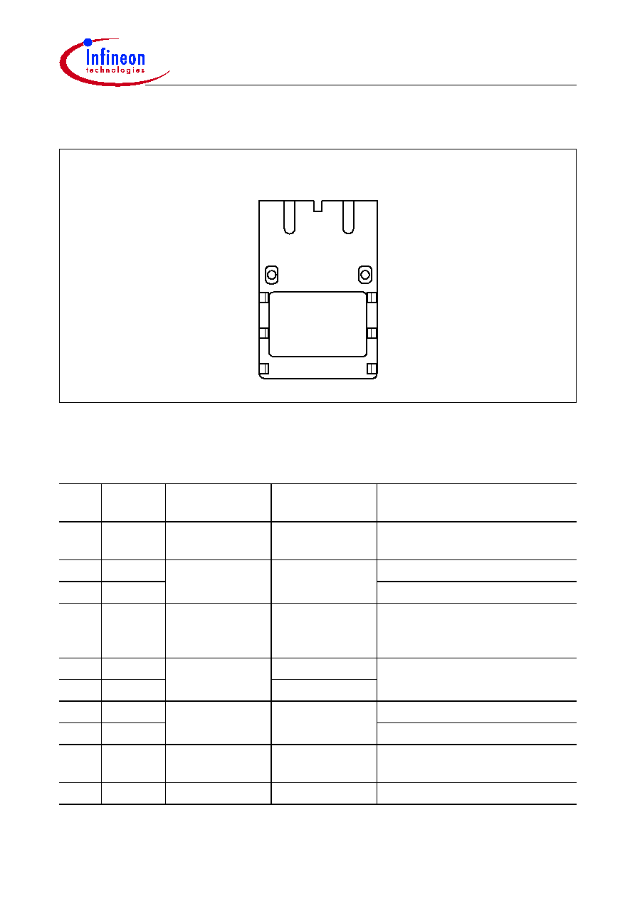
Pin Configuration
Figure 1
Pin Description
Pin
No.
Symbol
Level/Logic
Function
Description
1
Rx
V
EE
Power Supply
Rx Ground
Negative power supply,
normally ground
2
RD
PECL Output
Rx Output Data
Receiver output data
3
RDn
Inverted receiver output data
4
RxSD
PECL Output
active high
(TTL C53/353)
Rx Signal
Detect
High level on this output shows
there is an optical signal
5
Rx
V
CC
Power Supply
Rx 3.3 V/5 V
Positive power supply, 3.3 V/5 V
6
Tx
V
CC
Tx 3.3 V/5 V
7
TxDn
PECL Input
Tx Input Data
Inverted transmitter input data
8
TxD
Transmitter input data
9
Tx
V
EE
Power Supply
Tx Ground
Negative power supply,
normally ground
S1/S2 Case
Mech. Support
Support
Not connected
1 2 3 4 5 6 7 8 9
q
q
q
q
q
q
q
q
q
Rx
Tx
Top view
V23826-K15-Cxx/Cxxx
Description
Data Sheet
3
2000-03-09
Description
The Infineon single mode transceiver is based on the Physical Medium Depend (PMD)
sublayer and baseband medium, type 1000BASE-LX (Long Wavelength Laser)
(IEEE 802.5) and complies with the Fibre Channel Physical and Signaling Interface (FC-
PH), ANSI XSI TT Fibre Channel Physical Standard Class 100-SM-LL-I, latest Revision.
The appropriate fiber optic cable is 9 µm (mode field diameter) single mode fiber (up to
10 km) with Duplex SC connector.
The Infineon single mode transceiver is a single unit comprised of a transmitter, a
receiver, and an SC receptacle. This design frees the customer from many alignment
and PC board layout concerns. The module is designed for low cost LAN, WAN and
Gigabit Ethernet applications. It can be used as the network end device interface in
mainframes, workstations, servers, and storage devices, and in a broad range of
network devices such as bridges, routers, intelligent hubs, and local and wide area
switches.
This transceiver operates at 1.0625 and 1.3 Gbit/s from a single power supply (+5 V or
3.3 V). The full differential data inputs and outputs are PECL compatible.
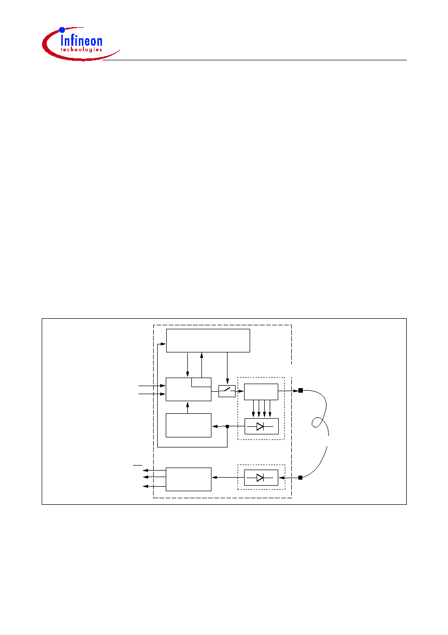
Functional Description
This transceiver is designed to transmit serial data via single mode or multimode cable.
Figure 2
Functional Diagram
The receiver component converts the optical serial data into PECL compatible electrical
data (RD and RDnot). The Signal Detect (SD, active high) shows whether an optical
signal is present.
The transmitter converts electrical PECL compatible serial data (TD and TDnot) into
optical serial data.
Laser
D river
Pow er
Control
Receiver
o/e
o/e
Laser
e/o
RX Coupling U nit
TD
TD
RD
RD
SD
Laser Coupling U nit
Single M ode Fiber
LEN
M onitor
Signal M onitor and
Autom atic Shut-D ow n
ISM *
*D C/D C
Version only

V23826-K15-Cxx/Cxxx
Description
Data Sheet
4
2000-03-09
The following versions are available:
1 AC/DC Transceiver: Tx is AC coupled. Differential 100
W
load. Rx has standard PECL
output and is DC coupled.
2 AC/AC TTL Transceiver: Tx and Rx are AC coupled. Tx has differential 100
W
load.
Signal Detect is TTL compatible.
3 DC/DC Transceiver: Standard PECL inputs and outputs Tx and Rx are DC coupled.
This version contains an Input Signal Monitor (ISM) which switches off the transceiver
if a continuous low level is applied at Data Input.
4 AC/AC PECL Transceiver: Tx and Rx are AC coupled. Tx has differential 100
W
load.
Signal Detect is PECL compatible.
The transmitter contains a laser driver circuit that drives the modulation and bias current
of the laser diode. The currents are controlled by a power control circuit to guarantee
constant output power of the laser over temperature and aging.
The power control uses the output of the monitor PIN diode (mechanically built into the
laser coupling unit) as a controlling signal, to prevent the laser power from exceeding the
operating limits.
Single fault condition is ensured by means of an integrated automatic shutdown circuit
that disables the laser when it detects transmitter failures. A reset is only possible by
turning the power off, and then on again.
The transceiver contains a supervisory circuit to control the power supply. This circuit
generates an internal reset signal whenever the supply voltage drops below the reset
threshold. It keeps the reset signal active for at least 140 milliseconds after the voltage
has risen above the reset threshold. During this time the laser is inactive.
Regulatory Compliance
Feature
Standard
Comments
Electrostatic Discharge (ESD)
to the Electrical Pins
MIL-STD 883C
Method 3015.4
Class 1 (> 1000 V)
Immunity:
Electrostatic Discharge (ESD)
to the Duplex SC Receptacle
EN 61000-4-2
IEC 61000-4-2
Discharges of
15 kV with an air
discharge probe on the receptacle
cause no damage.
Immunity:
Radio Frequency
Electromagnetic Field
EN 61000-4-3
IEC 61000-4-3
With a field strength of 10 V/m rms,
noise frequency ranges
from 10 MHz to 1 GHz. No effect
on transceiver performance
between the specification limits.
Emission:
Electromagnetic Interference
EMI
FCC Class B
EN 55022 Class B
CISPR 22
Noise frequency range: 30 MHz to
6 GHz; Margins depend on PCB
layout and chassis design

V23826-K15-Cxx/Cxxx
Technical Data
Data Sheet
5
2000-03-09
Technical Data
Exceeding any one of these values may destroy the device immediately.
Absolute Maximum Ratings
Parameter
Symbol
Limit Values
Unit
min.
max.
Package Power Dissipation
1)
1)
For
V
CC
≠
V
EE
(min., max.). 50% duty cycle. The supply current does not include the load drive current of the
receiver output.
1.5
W
Supply Voltage
3.3 V
5 V
V
CC
≠
V
EE
4
6
V
Data Input Levels (PECL)
V
CC
+0.5
Differential Data Input Voltage
2.5
Operating Ambient Temperature
0
70
∞C
Storage Ambient Temperature
≠40
85
Soldering Conditions Temp/Time
(MIL-STD 883C, Method 2003)
250 /5.5
∞C/s
Recommended Operating Conditions
Parameter
Symbol
Limit Values
Unit
min.
typ.
max.
Ambient Temperature
T
AMB
0
70
∞C
Power Supply Voltage
3.3 V
5 V
V
CC
≠
V
EE
3.1
4.75
3.3
5
3.5
5.25
V
Supply Current
1)
3.3 V
5 V
I
CC
230
270
mA
Transmitter
Data Input High Voltage DC/DC
V
IH
≠
V
CC
≠1165
≠880
mV
Data Input Low Voltage DC/DC
V
IL
≠
V
CC
≠1810
≠1475
Data Input Differential Voltage
2)
AC/DC, AC/AC TTL,
AC/AC PECL
V
DIFF
300
800
Input Data Rise/Fall Time
10% - 90%
t
R
,
t
F
100
750
ps