
Preliminary Product Information
1
2004-06-28
iSFPTM - Intelligent Small Form-factor Pluggable
1.25 Gigabit Ethernet (1000 Base-SX)
4.25/2.125/1.0625 Gbit/s Fibre Channel (400/200/100-M5/M6-SN-I)
Multimode 850 nm Transceiver with LCTM Connector
Preliminary Data Sheet
File: 1130
File: 1131
Fiber Optics
For ordering information see next page.
iSFPTM is a trademark of Infineon Technologies. LCTM is a trademark of Lucent.
V23849-R3x-C55
Features
∑ Small Form-factor Pluggable (SFP) MSA compatible
transceiver
1)
∑ Fully SFF-8472 compatible
∑ Incorporating Intelligent ≠ Digital Diagnostic
Monitoring Interface
∑ Internal calibration implementation
∑ Advanced release mechanism
∑ Easy access, even in belly to belly applications
∑ Wire handle release for simplicity
∑ Color coded black tab (multimode)
∑ PCI height compatible
∑ Excellent EMI performance
∑ Separate and common chassis/signal ground
module concepts available
∑ RJ-45 style LCTM connector system
∑ Single power supply (3.3 V)
∑ Extremely low power consumption of 530 mW typical
∑ Small size for high channel density
∑ UL-94 V-0 certified
∑ ESD Class 1C per JESD22-A114-B (MIL-STD 883D Method 3015.7)
∑ According to FCC (Class B) and EN 55022
∑ For distances of up to 860 m (50 µm fiber)
∑ Laser safety according to Class 1 FDA and IEC
∑ AC/AC Coupling according to MSA
∑ Extended operating temperature range of ≠20∞C to 85∞C
∑ SFP evaluation kit V23848-S5-V4 available upon request
∑ A press fit cage and cage plugs are available as accessory products from Infineon
(see
SFP Accessories
)
1)
MSA documentation can be found at
www.infineon.com/fiberoptics
under Transceivers, SFP Transceivers.
V23849-R3x-C55
Ordering Information
Preliminary Product Information
2
2004-06-28
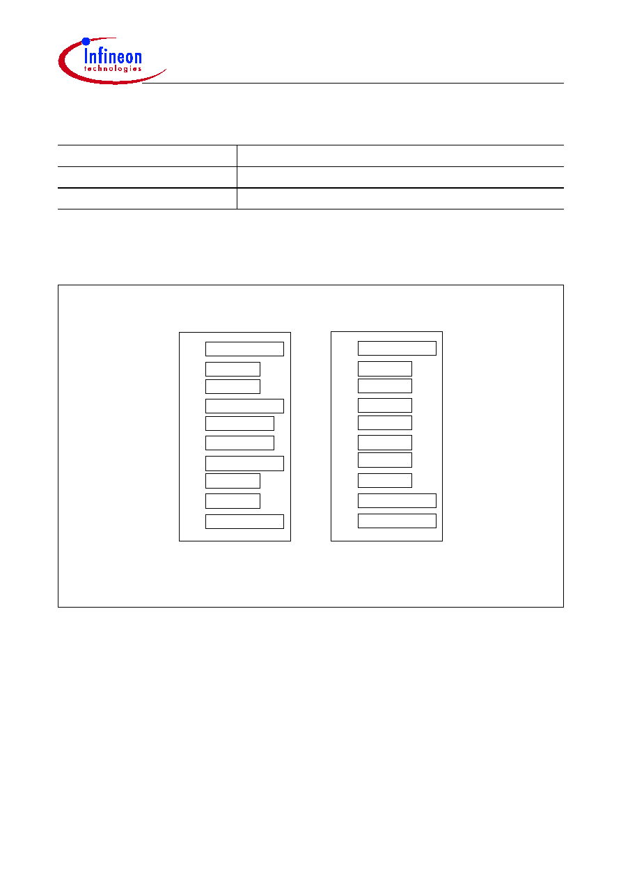
Pin Configuration
Figure 1
iSFPTM Transceiver Electrical Pad Layout
Ordering Information
Part Number
Chassis/Signal Grounding Concept
V23849-R35-C55
Common
V23849-R36-C55
Separated
V
EE
T
TD
-
TD+
V
EE
T
V
CC
T
V
CC
R
V
EE
R
RD+
RD
-
V
EE
R
20
19
18
17
16
15
14
13
12
11
V
EE
T
Tx Fault
Tx Disable
MOD-DEF(2)
MOD-DEF(1)
MOD-DEF(0)
Rate Select
LOS
V
EE
R
V
EE
R
1
2
3
4
5
6
7
8
9
10
Top of transceiver
Bottom of transceiver (as viewed
through top of transceiver)
File: 1306

V23849-R3x-C55
Pin Configuration
Preliminary Product Information
3
2004-06-28
Pin Description
Pin No.
Name
Logic Level
Function
1
V
EE
T
N/A
Transmitter Ground
1)
2
Tx Fault
LVTTL
Transmitter Fault Indication
2)
10)
3
Tx Disable
LVTTL
Transmitter Disable
3)
4
MOD-DEF(2)
LVTTL
Module Definition 2
4)
10)
5
MOD-DEF(1)
LVTTL
Module Definition 1
5)
10)
6
MOD-DEF(0)
N/A
Module Definition 0
6)
10)
7
Rate Select
7)
LVTTL
1 & 2 or 2 & 4 Gbit/s
8)
8
LOS
LVTTL
Loss Of Signal
9)
10)
9
V
EE
R
N/A
Receiver Ground
1)
10
V
EE
R
N/A
Receiver Ground
1)
11
V
EE
R
N/A
Receiver Ground
1)
12
RD≠
LVPECL
Inv. Received Data Out
11)
13
RD+
LVPECL
Received Data Out
11)
14
V
EE
R
N/A
Receiver Ground
1)
15
V
CC
R
N/A
Receiver Power
12)
16
V
CC
T
N/A
Transmitter Power
12)
17
V
EE
T
N/A
Transmitter Ground
1)
18
TD+
LVPECL
Transmit Data In
13)
19
TD≠
LVPECL
Inv. Transmit Data In
13)
20
V
EE
T
N/A
Transmitter Ground
1)
1)
Common transmitter and receiver ground within the module.
2)
A high signal indicates a laser fault of some kind and that laser is switched off.
3)
A low signal switches the transmitter on. A high signal or when not connected switches the transmitter off.
4)
MOD-DEF(2) is the data line of two wire serial interface for serial ID.
5)
MOD-DEF(1) is the clock line of two wire serial interface for serial ID.
6)
MOD-DEF(0) is grounded by the module to indicate that the module is present.
7)
Not implemented.
8)
In accordance to SFF Committee SFF-8079 Draft.
9)
A low signal indicates normal operation, light is present at receiver input. A high signal indicates the received
optical power is below the worst case receiver sensitivity.
10)
Should be pulled up on host board to
V
CC
by 4.7 - 10 k
.
11)
AC coupled inside the transceiver. Must be terminated with 100
differential at the user SERDES.
12)
Common transmitter and receiver
V
CC
within the module.
13)
AC coupled and 100
differential termination inside the transceiver.

V23849-R3x-C55
Description
Preliminary Product Information
4
2004-06-28
Description
The Infineon Fibre Channel multimode transceiver ≠ part of Infineon iSFPTM family ≠ is
compatible to the Physical Medium Depend (PMD) sublayer and baseband medium,
type 1000 Base-SX (short wavelength) as specified in IEEE Std 802.3 and Fibre Channel
FC-PI-2 (Rev. 5.0) 400-M5-SN-I, 400-M6-SN-I for 4.25 Gbit/s,
FC-PI-2 (Rev. 5.0) 200-M5-SN-I, 200-M6-SN-I for 2.125 Gbit/s, and
FC-PI-2 (Rev. 5.0) 100-M5-SN-I, 100-M6-SN-I for 1.0625 Gbit/s.
The appropriate fiber optic cable is 62.5 µm or 50 µm multimode fiber with LCTM
connector.

V23849-R3x-C55
Description
Preliminary Product Information
5
2004-06-28
Link Length as Defined by IEEE and Fibre Channel Standards
Fiber Type
Reach
Unit
min.
1)
max.
2)
at 1.0625 Gbit/s
50 µm, 2000 MHz*km
0.5
860
meters
50 µm, 500 MHz*km
0.5
500
50 µm, 400 MHz*km
0.5
450
62.5 µm, 200 MHz*km
0.5
300
62.5 µm, 160 MHz*km
0.5
250
at 1.25 Gbit/s
50 µm, 500 MHz*km
2
550
meters
50 µm, 400 MHz*km
2
500
62.5 µm, 200 MHz*km
2
275
62.5 µm, 160 MHz*km
2
220
at 2.125 Gbit/s
50 µm, 2000 MHz*km
0.5
500
meters
50 µm, 500 MHz*km
0.5
300
50 µm, 400 MHz*km
0.5
260
62.5 µm, 200 MHz*km
0.5
150
62.5 µm, 160 MHz*km
0.5
120
at 4.25 Gbit/s
50 µm, 2000 MHz*km
0.5
270
meters
50 µm, 500 MHz*km
0.5
150
50 µm, 400 MHz*km
0.5
130
62.5 µm, 200 MHz*km
0.5
70
62.5 µm, 160 MHz*km
0.5
55
1)
Minimum reach as defined by IEEE and Fibre Channel Standards. A 0 m link length (loop-back connector) is
supported.
2)
Maximum reach as defined by IEEE and Fibre Channel Standards. Longer reach possible depending upon link
implementation.