 | –≠–ª–µ–∫—Ç—Ä–æ–Ω–Ω—ã–π –∫–æ–º–ø–æ–Ω–µ–Ω—Ç: IL33091AN | –°–∫–∞—á–∞—Ç—å:  PDF PDF  ZIP ZIP |
IL33091AN,
IL33091AD
1
Powerful High-grade FET driver
Description of basic functions.
Developed microcircuit is a high-performance driver of high -potential power field MOS
transistor control designed for use in harsh automotive switching applications requiring the
capability of handling high voltages on power line
attributed to transient commutation of loads in
conditions of automobile exploitation.
Load of microcircuit is a device on the base
of MOS transistors that enables switching high
current levels in automobile electrical system.
Microcircuit has Fault indication output when
there is short circuit in load or when load
transistor current level exceeds preset value.
Functions
Microcircuit provides pumping of charge (on
output capacity on pin Gate of gate control)to
drive power MOS transistor. Input Input ,
compatible with logic levels of CMOS
microcircuits ,controls pumping of charge (switch
in/switch off).
Check of drain-source voltage is implemented
(VDS) on power ÃŒS transistor, detection of
shorted load , presentation of error signal on pin
Fault.
Microcircuit has pin V
T
of timer, that is both input in timer window comparators and
output of current square circuit, depending on r m s voltage drain-source on power MOS
transistor, as power dissipated in ÃŒS device is proportional to VDS
2
.
External resistor R
T
and capacitor C
T
, connected to timer pin enable programming of
timing data necessary for protection of power MOS-device.
Internal circuit of stabilizer diodes with the total break down voltage of about 30V
provides protection of microcircuit and power ÃŒS transistor from supply voltage value to
be exceeded. Activation of microcircuit Zener stabilizer diodes attributed to switching-off
ÃŒS transistor for the time when supply voltage value exceeded , in addition pin Fault
does not change its logic state .
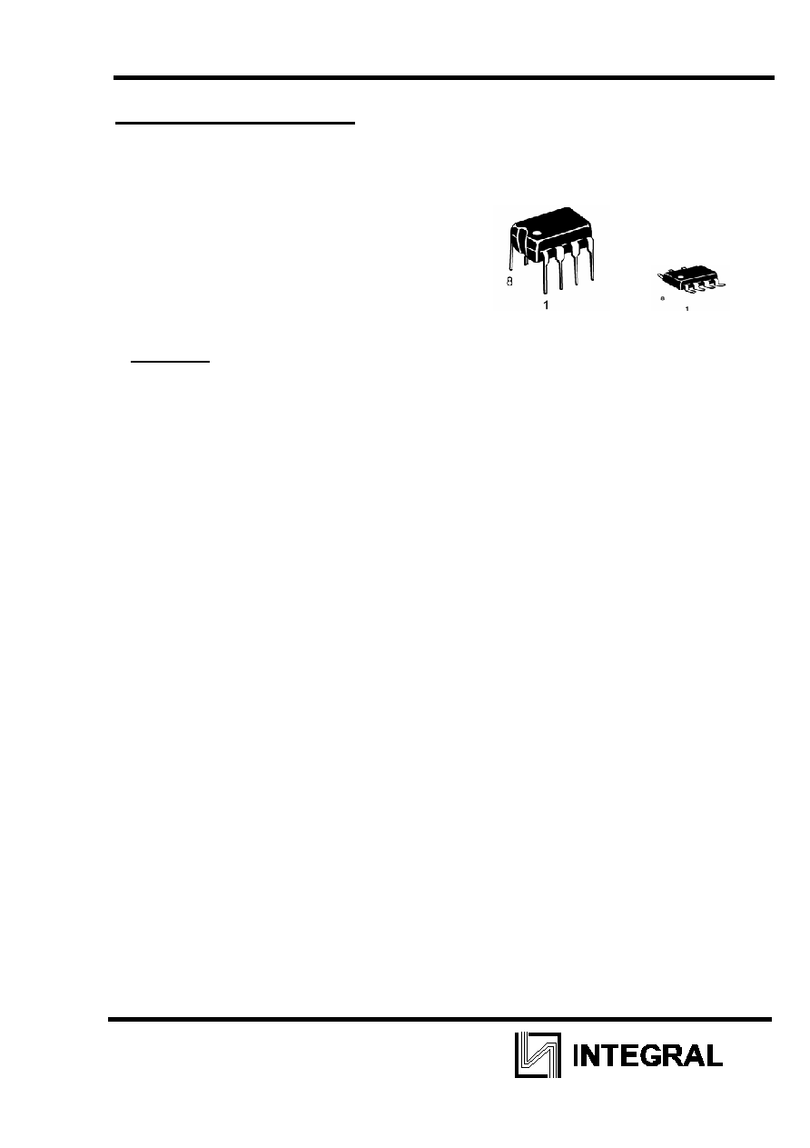
IL33091AN
IL33091AD
Designation of microcircuit in plastic
packages:
IL33091AN - in DIP-package MS-
001BA
IL33091AD - ¬ SO-package MS-012AA
T
A
= -40
ü +125ú—
package drawingsÛÌÍË ÍÓÔÛÒÓ‚
IL33091AN,
IL33091AD
2
Features.
û Works with a wide variety of N-channel power field transistors
û Input of control compatible with CMOS logic
û Built in pumping of charge without external components
û Detection and protection from shorted load and current exceeding
û Failure unit reporting a FET overcurrent and shorted load condition
û Possibility to connect induced loads
û Forward overvoltage and battery polarity reverse protection
û Extended range of operating temperatures
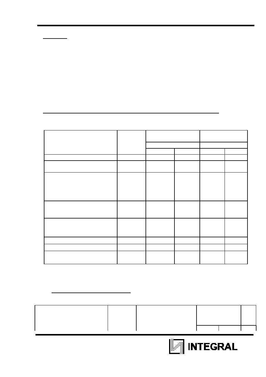
Table of Maximum operation ratings and absolute maximum ratings .
Maximum operation ratings and absolute maximum ratings of exploitation
Name of parameter , unit of
measurement
Symbol Maximum
operation
rating
Absolute
maximum rating
Standard
Standard
min
max
min
max
1 2
3
4
5
6
supply voltage on output V
CC
(pin 05), V
V
CC
7,0
24,0
-0,7
28,0
Consumption current in mode
of limiting by protection (input
05), m¿
DIP package
SO-8 package
I
C
10
1,0
Range of adjusting voltage on
input Input (pin 07),V
(direct voltage)
Vin
-0,7
28,0
range of voltage, delivered to
pin (pin 06), V
(direct voltage)
V
OUT
-0.7
28,0
Temperature of chip,
ú—
T
J
-65
150
Temperature of storage,
ú—
T
STG
-65
150
operation range of ambient
temperatures,
ú—
“
A
-40
125
-65
150
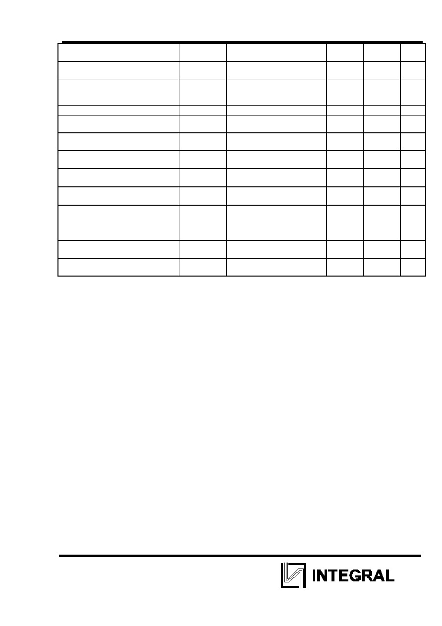
“able of electrical parameters .
Electrical parameters of microcircuits
IL33091AN, IL33091AD
Name of parameter,
unit of measurement
Symbol
Mode of measurement
standard
note
min
max
IL33091AN,
IL33091AD
3
consumption current, m¿
Icc
Vin = 0 V:
Vin=5,0 V (Rx=100 kŒhm):
- 0,3
6,0
2
Limitation value of supply voltage
on pin Vcc (pin 05), V
Vz
29,0
35,0
3
output voltage range on pin
Gate (pin 04) relatively voltage
of power supply source Vcc, V
V
GS
8,0
15,0
-
current on pin Gate (pin 04),
¿
I
G
V
G
=Vcc
30 400 -
output voltage of saturation on
pinGate (pin 04), V
V
G
(sat)
I
G
=10
¿
0 1,4
-
voltage on pin Gate in mode of
load short circuit (pin 06), V
V
GC
6,4
7,7
4
Threshold voltage on input
Input (pin 07), V
V
IL
V
IH
-
3,5
1,5
-
-
input current of pin Input (pin
07),
¿
Iin
Vin=5,0 V
-
250
-
current coefficient of timer (pin
08),
¿/V
2
Rx=100
kŒhm, VÚ=0,
V
DC
=1,0 V
0,7 1,5 5
threshold voltage of
synchronization (pin 08), V
lower level
upper level
V
TL
V
TH
0,4
4,3
1,2
5,2
-
current on pin (pin 06),
¿
I
OL
I
OH
V
F
=5,0 V
V
F
=0
500
-
-
0,1
-
Voltage of saturation on pin
(pin 06), V
V
OL
I
F
=500
¿
- 0,8
-
Note
1 .Standards for electrical parameters of table , unless otherwise noted , are given for
conditions :
7,0 V
ò Vcc ò 24 V; -40ú— ò “a ò125ú—.
2 .Measure total consumption current on pins 02 and 05 of microcircuit (when resistor is
Rx=100 kŒhm, connected to pin 02, and resistor with the value of 45 kŒhm, connected to
pin 06).
3 . Protection of device from short-term voltage surge on power line at the expense of
internal circuit of semiconductor stabilitrons.
4. Measure voltage relatively pin SRC in shorted load mode , when voltage on load
approximately will make less than 1¬ in Õ” relatively potential general. Mode of
measurements , residual stress on load of short-circuit mode are to be specified in the
course of development basing on the reference dependence reading results for
temperature range.
5 Current coefficient of timer is a constant (coefficient )of proportionality of voltage into
current conversion, used to check V
DS
voltage, formed on field transistor.
For microcircuit IL33091AN, arranged in 8-pin plastic DIP-package of MS-001BA type,
Rtja is 100
ú—/W; For microcircuit IL33091AD - arranged in 8-pin plastic SO-package of
MS-012AA MC33091AD type, Rtja is 145
ú—/W.
permissible value of static potential value is 2000 V (human body model).
Nominal block diagram and IC connection circuit

IL33091AN,
IL33091AD
4

IL33091AN,
IL33091AD
5
“able of pin purpose.
Table of pin purpose of microcircuits IL33091AN, IL33091AD
of pin
Purpose of pin
01
pin of voltage check on load (SRC)
02
pin for connection to resistor generating current dependence from
voltage on external transistor (DRN)
03
general pin (GND)
04
pin of external transistor gate control (Gate)
05
pin of connection to supply voltage chain (Vcc)
06
pin of emergency indication ()
07
control input (Input)
08
pin of timer timesetting circuit (VÚ)