TECHNICAL DATA
DUAL OPERATIONAL AMPLIFIER
IL4580
GENERAL DESCRIPTION
The IL4580 is the dual operational amplifier, specially designer for
improving the tone control, which is most suitable for the audio application.
ORDERING INFORMATION
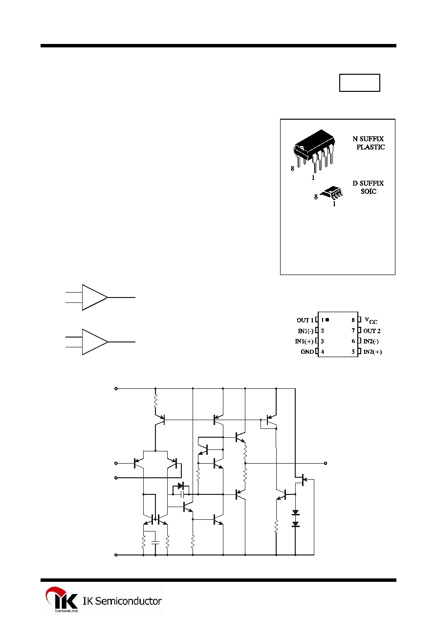
IL4580N Plastic
IL4580D SOIC
T
A
= -40
ú to 85ú C
for all packages.
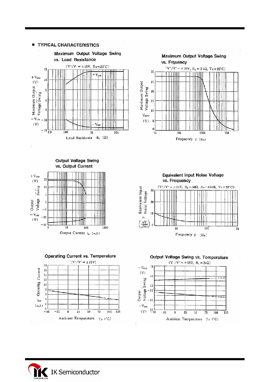
Featuring noiseless, higher gain bandwidth, high output current and low
distortion ratio, and it is most suitable not only for acoustic electronic parts of
audio pre-amp and active filter, but also for the industrial measurement tools.
It is also suitable for the head phone amp at higher output current, and further
more, it can be applied for the handy type set operational amplifier of general
purpose in application of low voltage single supply type which is properly
biased of the input low voltage source.
FEATURES
û
Operating Voltage
(2 V
18 V)
û
Wide Gain Bandwidth Product (15 MHz typ.)
û
Slew Rate
(5 V/
s typ.)
û
Bipolar Technology
BLOCK DIAGRAM
A -INPUT
+
+
-
-
A +INPUT
B -INPUT
B +INPUT
1
2
3
6
5
7
A OUTPUT
B OUTPUT
PIN ASSIGNMENT
EQUIVALENT CIRCUIT (1/2 Show)
Output
V
V
-INPUT
+INPUT
+
-
1
IL4580
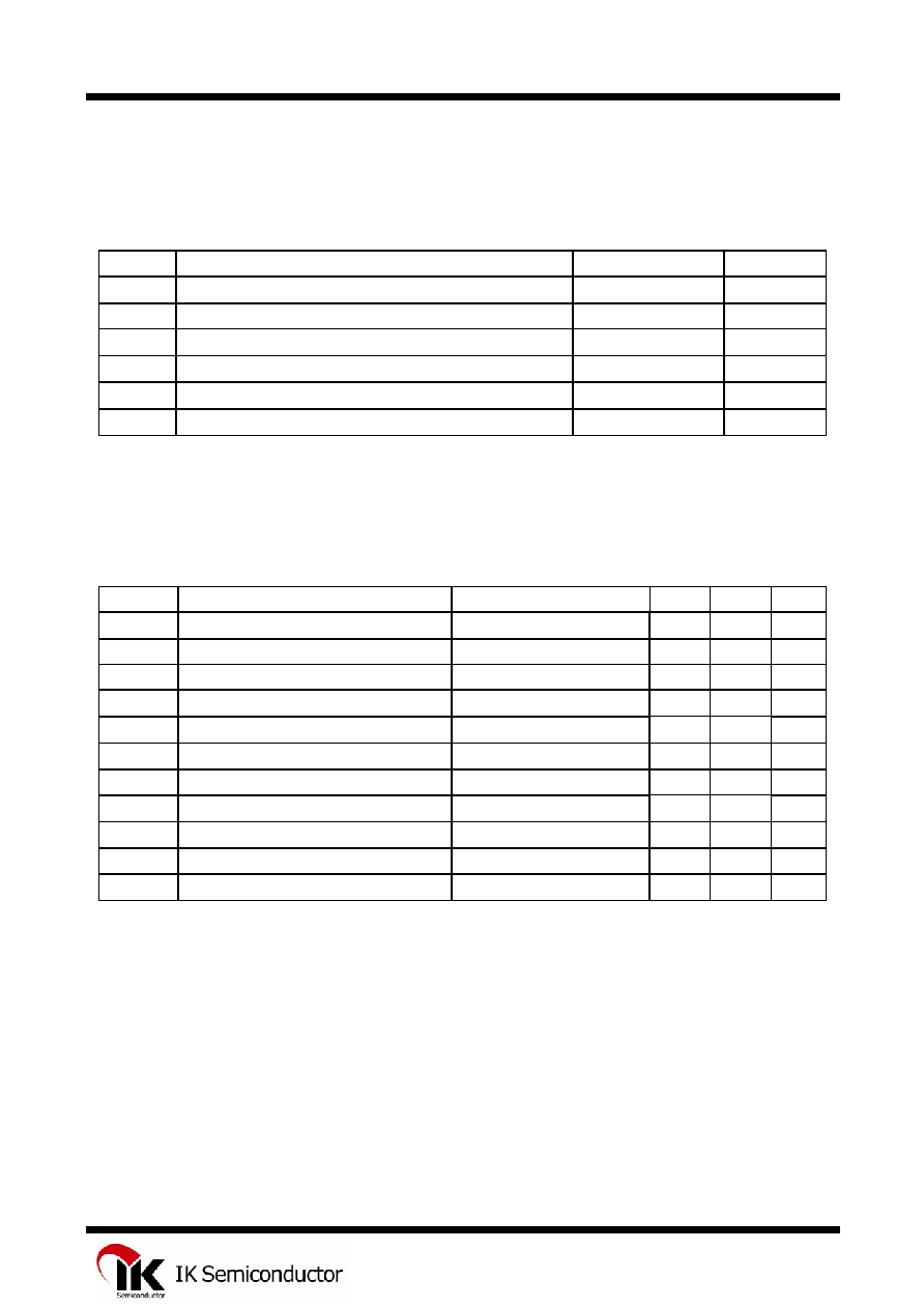
ABSOLUTE MAXIMUM RATINGS
(Ta=25
úC)
Symbol Parameter
Ratings
Unit
V
+
/V
-
Supply Voltage
18
V
V
ID
Differential Input Voltage
30
V
V
IC
Input Voltage
15*
V
I
O
Output Current
50
mA
Topr
Operation Temperature Range
-40
+85
úC
Tstg
Storage Temperature Range
-60
+125
úC
*
For supply voltage less then
15 V, the absolute maximum input voltage is equal to the supply voltage.
ELECTRICAL CHARACTERISTICS
(Ta=25
úC, V
+
/V
-
=
15)
Symbol Parameter
Test
Condition
Min
Max
Unit
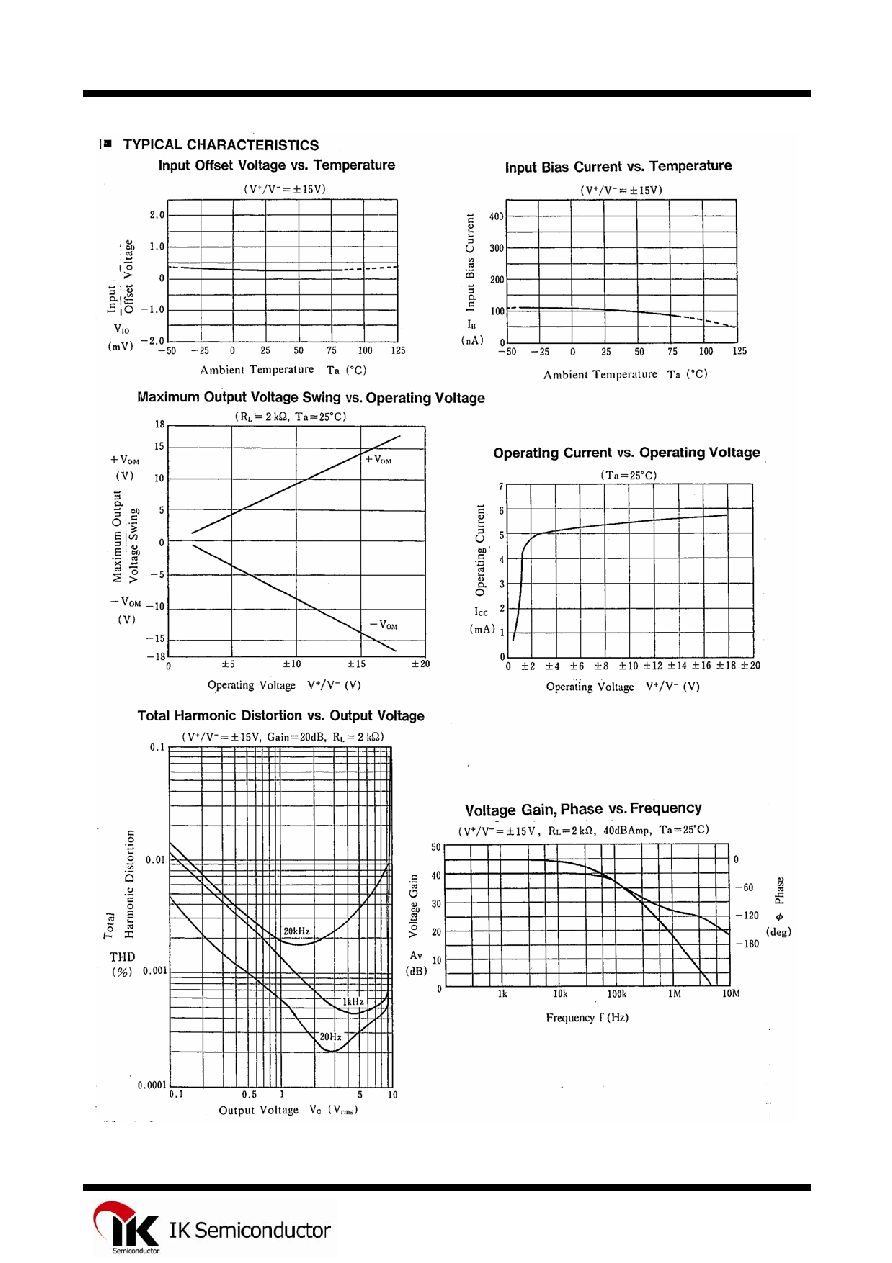
V
IO
Input Offset Voltage
R
S
ò 10 k
- 3
mV
I
IO
Input Offset Current
-
200
nA
I
B
Input Bias Current
-
500
nA
R
IN
Input Resistance
0.3
-
M
A
V
Large Signal Voltage Gain
R
L
ô 2 k
, V
O
= 10 V
90 - dB
V
OM
Output Voltage Swing
R
L
ô 2 k
12 - V
V
ICM
Input Common Mode Voltage Range
12
-
V
CMR
Common Mode Rejection Ratio
R
S
ò 10 k
80 - dB
SVR
Supply Voltage Rejection Ratio
R
S
ò 10 k
80 - dB
I
CC
Operating Current
-
9
mA
SR Slew
Rate
R
L
ô 2 k
4 6
V/
s
2
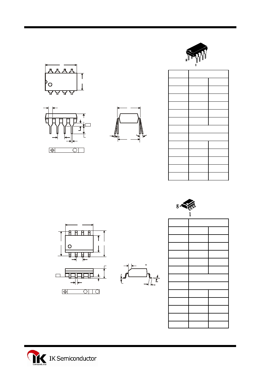
IL4580
N SUFFIX PLASTIC DIP
(MS - 001BA)
Symbol
MIN
MAX
A
8.51
10.16
B
6.1
7.11
C
5.33
D
0.36
0.56
F
1.14
1.78
G
H
J
0ú
10ú
K
2.92
3.81
NOTES:
L
7.62
8.26
1.
Dimensions "A", "B" do not include mold flash or protrusions.
M
0.2
0.36
Maximum mold flash or protrusions 0.25 mm (0.010) per side.
N
0.38
D SUFFIX SOIC
(MS - 012AA)
Symbol
MIN
MAX
A
4.8
5
B
3.8
4
C
1.35
1.75
D
0.33
0.51
F
0.4
1.27
G
H
J
0ú
8ú
NOTES:
K
0.1
0.25
1.
Dimensions A and B do not include mold flash or protrusion.
M
0.19
0.25
2.
Maximum mold flash or protrusion 0.15 mm (0.006) per side
P
5.8
6.2
for A; for B 0.25 mm (0.010) per side.
R
0.25
0.5
1.27
5.72
Dimension, mm
Dimension, mm
2.54
7.62
A
B
H
C
K
C M
J
F
M
P
G
D
R x 45
SEATING
PLANE
0.25 (0.010) M T
-T-
1
8
4
5
L
H
M
J
A
B
F
G
D
SEATING
PLANE
N
K
0.25 (0.010) M T
-T-
C
1
8
4
5
5