 | –≠–ª–µ–∫—Ç—Ä–æ–Ω–Ω—ã–π –∫–æ–º–ø–æ–Ω–µ–Ω—Ç: IL91210E | –°–∫–∞—á–∞—Ç—å:  PDF PDF  ZIP ZIP |

TECHNICAL DATA
IL91210E
Tone/Pulse Dialer
High-Performance Silicon-Gate CMOS
ORDERING INFORMATION
IL91210EN
T
A
= -20
ú to 70ú C
The IL91210E is a single-chip, silicon gate, CMOS integrated circuit
with an on-chip oscillator for a 3.58 MHz crystal or ceramic resonator. It
provides dialing pulse (DP) or dual tone multi-frequency (DTMF)
dialing. A standard 4x4 matrix keyboard can be used to support either DP
or DTMF modes. Up to 32 digits can be saved in the on-chip RAM for
reading. In the DTMF mode, minimum tone duration and minimum
intertone pause are provided for rapid dialing. Maximum tone duration is
dependent upon the key depression time in manual dialing.
û
One touch redial operation
û
Tone/Pulse switchable
û
32-digit capacity for redialing
û
Automatic mixed redialing (last number redial) of pulse to DTMF
with multiple automatic access pauses
û
PABX auto-pause is 2.2 second
û
DTMF Timing:
Manual dialing: minimum duration for bursts and pauses
Redialing: calibrated timing
û
Wide operating voltage range: 2 V to 5.5 V
û
Digits dialed manually after redialing are cascadable and stored as additional digits for the next redialing
û
Uses inexpensive ceramic resonator (3.58 MHz)
û
Built-in power up reset circuit
û
Four extra function keys: flash, pause, redial and DP or DTMF mixed dialing
û
Four-by-four (or 2 of 8) keyboard can be used
û
Low standby current
û
Dial Pulse Rate: 10 pps
PIN ASSIGNMENT
IL91210E
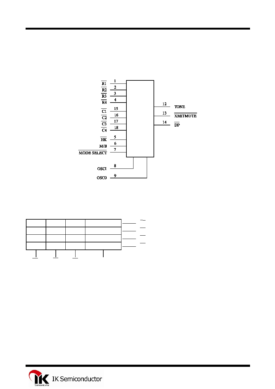
LOGIC DIAGRAM
PIN 11 = GND
PIN 10 = V
CC
Keyboard Assignments*
1 2 3
F1
R1
4 5 6
F2
R2
7 8 9
P
R3
*/T 0 #
RD
R4
C1 C2 C3 Internal
Pull
Low
*Notes:
1.
*/T - At Pulse mode this key works as Pulse -> DTMF key (T key), at DTMF mode the key works as *key.
*/T key will occupy one memory digit in either mode.
2.
F1 - Flash key. The break time is 96 ms.
3.
F2 - Flash key for break time 640 ms.
4.
P -- Pause key (2.2 seconds).
5.
RD - One key redial key.
6.
# - At pulse mode this key input is neglected, at DTMF mode this key works as # key.
IL91210E
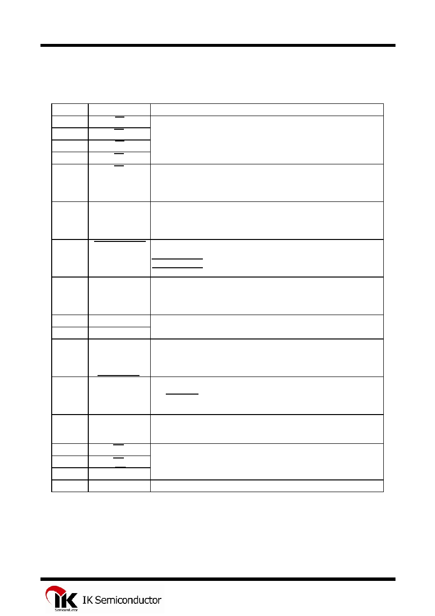
Pin Description
Pin No.
Designation
Description
1 R1
2 R2
3 R3
4 R4
5
HK
Hook switch input.
This inverter input pin detects the state of the hook switch contact. "Off
Hook" is represented by a GND condition. "On Hook" is represented by a
V
CC
condition.
6
M/B
Make/Break Ratio Select Input.
This input allows selection of the Make/Break ratio.
M/B = V
CC
: 1/2
M/B = GND : 2/3
7
MODE SELECT Mode select input.
This input allows the selection of pulse mode or DTMF mode.
MODE SELECT = V
CC
: Pulse mode operation
MODE SELECT = GND : Tone mode operation
8
9
OSCI
OSC0
Oscillator Input and Output pins.
The time base for IL91210E is a crystal controlled on-chip oscillator, which
is completed by connecting a 3.58 MHz crystal or ceramic resonator
between OSCI and OSC0 pins.
10 V
CC
11 GND
12
TONE
Tone dialing output.
When a valid keypress is detected in the DTMF mode, appropriate low
group and high group frequencies are generated, which hybridize the dual
tone output. TONE output is in the "OFF" state in pulse mode.
13
XMITMUTE
Dialing transmission mute output.
This is an N-channel open drain output
The XMIMUTE is normally "OFF". During pulse or DTMF dialing this
output is "ON".
14
DP
Dialing pulse output.
This is an N-channel open drain output. The normal output will be "ON"
during Break and "OFF" during Make in the pulse dialing mode.
15 C1
16 C2
17 C3
18
C4
Internal Pull low.
Key board pins.
These inputs serve as the interface to a 4x4 matrix keyboard.
Power supply pins.
This device is designed to operate from 2.0 V to 5.5 V.
Key board pins.
These inputs serve as the interface to a 4x4 matrix keyboard.

IL91210E
Operation Procedures
Symbol Definitions:
In the description below, signals are defined in terms of
the key or switch which is activated.
Off Hook
means the phone was taken off
the hook.
On Hook
means that the receiver is onf the
hook.
D1
stands for the first digit dialed in a string
of digits.
Dn
stands for the last digit dialed in a string
of digits.
Dn+1
stands for the beginning of a new
string of digits.
Dn+m
stands for the last digit in a new string
of digits.
*/T
is the Pulse-to-DTMF key
RD
is the Redial key
O
is the Zero key.
P
is the Pause key.
F
is the Flash key.
1. Pulse mode operation
a.
Off Hook
D1
. . . . . .
Dn
Pulse mode is defined as the initial mode, provided
the first keyboard input is not the */T key following
the Off Hook condition and the mode selection pin is
V
CC
(MODE SELECT = V
CC
).
b. Pulse mode is defined as the initial mode, provided
the key input D1 is not */T while the mode selection
pin is V
CC
. The chip will pause for 824 ms
automatically after it detects an Off Hook condition.
It then proceeds with pulse or DTMF dialing if any
keys have been depressed. The dialing rate or
make/break ratio is decided at the first key entry by
checking the MODE SELECT & M/B status and will
not be altered. The MODE SELECT status can only
switch the dialing mode from Pulse to DTMF after
the first key entry.
2. DTMF mode operation
a.
Off Hook
D1
. . . . . .
Dn
DTMF mode is defined as the initial mode of the
mode selection pin if MODE SELECT is GND.
b.
Off Hook
*/T
D1
. . . . . .
Dn
The initial mode is pulse mode if the mode selection
pin, MODE SELECT, is V
CC
. The */T key can
switch the dialing mode to tone mode.
Unlike normal mode switching, the */T key entry, as
the first key pressed, will not produce any pause
time. There are only 31 digit of redial memory
available in the buffer to be used for operations a
and b, since the mode switching key, */T , will
occupy one digit of space.
3. Manual dialing with automatic access pause
Off Hook
O
*/T
D1
. . . .
Dn
Pause key entries can be accepted and stored in the
redial memory. Each is stored as a digit. Each key-in
will provide a pause of 2.2 seconds, depending on
which model you are using.
4. Redial
a.
Off Hook
RD
Up to 32 digits (in pulse mode) or 31 digits (in tone
mode) can be dialed using the RD is disabled while
pulse or tone signals are being transmitted. Redial
will also be inhibited if the last number dialed
exceeds 32 digits because the redial memory can
only hold 32 digits.
b.
Off Hook
RD
D1
. . . . . .
Dn
After pressing the RD key, we can add digits to the
number in redial memory. When finished dialing, the
redial memory will contain the original digits plus
the digits dialed after pressing RD. Each time the
redial key is pressed, the stored number will be
dialed exactly the same as it was previously,
regardless of the status of the MODE SELECT pin.
5. TONE/PULSE switching operation
a. Off Hook D1 . . . Dn
MODE SELECT pin Pulse Mode switched to GND
Dn+1 . . . . Dn+m DTMF Mode
The mode selection pin is always checked for tone or
pulse mode key entry. Dialing can be switched from
pulse to tone mode, but not from tone to pulse mode.
Switching the MODE SELECT pin to GND will
cause the chip to store a */T digit prior to the
first tone digit in the redial memory and will
automatically insert a 2.2 second pause before the
tone digits are dialed out. After the mode has been
switched, the status of the mode selection pin will no
longer be checked. Therefore, it will not be possible
to switch from tone to pulse mode.
IL91210E
b. Off Hook D1 . . . Dn */T Dn+1 Pulse Mode
Dn+m DTMF Mode
If the dialing of D1 to Dn is completed, pressing RD
will cause the pulse dialing pin to go low for
2.2 seconds of break time and an 824 ms pause will
automatically be added. Otherwise, the pressing of
the redial key will be ignored.
Pulse mode is initially defined with the mode
selection pin, MODE SELECT, equal to V
CC
. At this
time, the mode can be switched to DTMF by
pressing the */T key. DTMF mode will begin as
soon as the last pulse has been transmitted. In this
mode, Dn+1 through Dn+m are sent through the
TONE OUT pin as DTMF signals. If a P key entry
is contained in the series of digits before or after the
*/T entry, or the MODE
SELECT switch is
depressed, 2.2 second pause will be added to the
automatically inserted pause time, which is also
2.2 seconds. Both of the above switching modes can
store as many as 31 digits in the redial memory.
6. One-Key redialing
Off Hook
D1
. . . . . .
Dn
RD
7. Flash dialing
Off Hook
F
D1
. . . . . .
Dn
The flash keys emulate quick On-Off Hook
operations. Pressing the flash keys, F1 or F2, will
cause a break of 96 ms or 640 ms on the DP output
pin. Then, it will pause for 824 ms and continue
dialing the digits, D1 to Dn . These digits are then
stored in the redial memory. Each time the flash key
is pressed, the redial memory will be cleared to store
a new entry. In addition, the MODE SELECT status
will be checked again for the setting of the
Tone/Pulse dialing mode.
Similarly, to make sure that the IC is working
properly, new flash key inputs will be ignored as
long as the digits that were dialed have not finished.
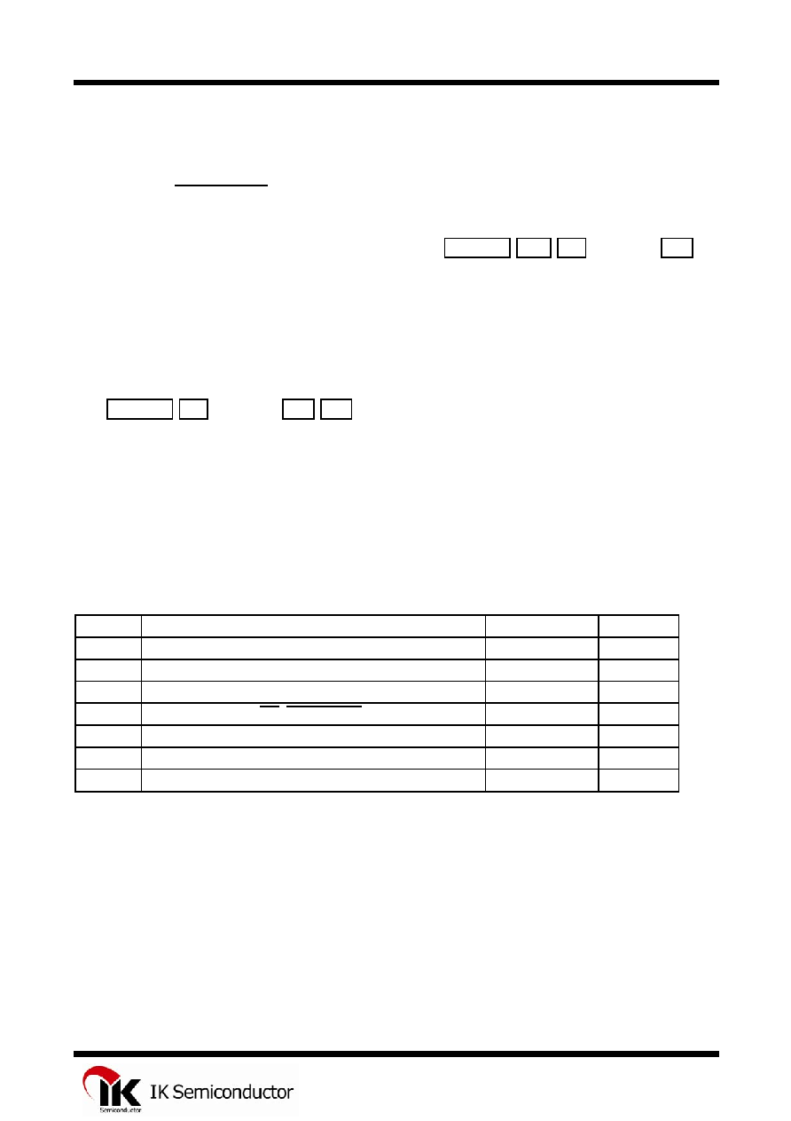
MAXIMUM RATINGS
*
Symbol Parameter
Value
Unit
V
CC
DC Supply Voltage (Referenced to GND)
-0.3 to +6.0
V
V
IN
DC Input Voltage (Referenced to GND)
-0.3 to V
CC
+0.3
V
V
OUT
DC Output Voltage (Referenced to GND)
-0.3 to V
CC
+0.3
V
V
OUT
DC Output Voltage (DP, XMITMUTE)
-0.3 to 1.2
V
I
TONE
DC Output Current(Tone)
50
mA
P
D
Power Dissipation in Still Air,
Plastic DIP
**
500 mW
Tstg
Storage Temperature
-40 to +125
úC
*
Maximum Ratings are those values beyond which damage to the device may occur.
Functional operation should be restricted to the Recommended Operating Conditions.
**
Durating: -10
mW
/
úC
from 65
úC to 70úC.