 | –≠–ª–µ–∫—Ç—Ä–æ–Ω–Ω—ã–π –∫–æ–º–ø–æ–Ω–µ–Ω—Ç: ILA1185A | –°–∫–∞—á–∞—Ç—å:  PDF PDF  ZIP ZIP |
ILA1185A
1
T
RIAC
P
HASE
A
NGLE
C
ONTROLLER
The ILA1185A generates controlled triac triggering pulses and allows tachless speed
stabilization of universal motors by an integrated positive feedback function. Typical
applications are power hand tools, vacuum cleaners, mixers, light dimmer and other small
appliances.
û Supply Power Obtained from AC Line
û Can be used with 220 V/50 Hz or 110 V/60
Hz
û Low Count/Cost External Components
û Optimum Triac Firing (2nd and 3rd
Quadrants)
û Repetitive Trigger Pulses when Triac
Current is Intenupted
by Motor Brush Bounce
û Triac Current Sensing to Allow Inductive
Loads
û Programmable Soft-Start
û Power Failure Detection and General
Circuit Reset
û Low Power Consumption; 6.0 mA
Pin Connection
1 14
2 13
3 12
4 11
5 10
6 9
7 8
V
EE
V
CC
Gate trigger
Soft start
NC
Finning Angle Set
Ramp Generator
NC
NC
Bias Current
Current Cense
Feedback Input
Voltage Cense
Integration Cap
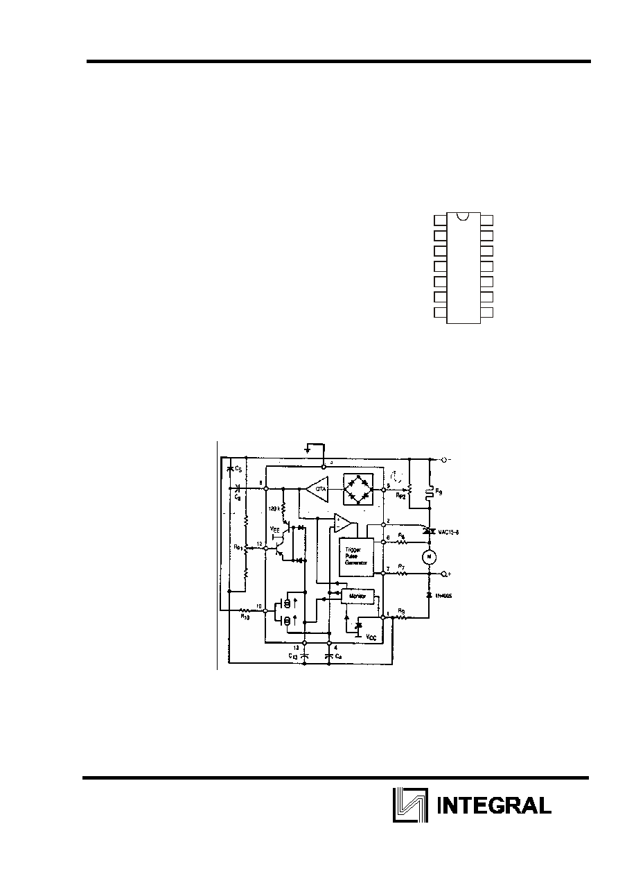
Figure 1. Representative Block Diagram

ILA1185A
2
MAXIMUM RATINGS (voltages are referenced to Pin 14 (ground) unless other noted)
Rating Symbol
Value
Unit
Maximum Voltage Range per Listed Pin Pins3. 5,11
(not connected)
Pins 4,8.13
Pin 2
Maximum Positive Voltage (No minimum value
allowed; see current ratings)
V
pin
V
pin12
V
pin1
-20 to+20
-V
CC
to 0
-3.0 to +3.0
0
0.5
V
Maximum Current per Listed pin
Pin 1
Pin 6 and 7
–in 9
Pin 10
Pin12
I
pin
20
2.0
0.5
300
-500
mA
mA
mA
A
A
Maximum Power Dissipation (“
A
=25
o
—) P
D
250
mW
Maximum Thermal Resistance, .Junction-to-Ambient
R
JA
100
o
C/W
Operating Ambient Temperature Range
T
A
0 to + 70
o
C
Storage Temperature Range
Tstg
-55 to <+ 125
o
C
ELECTRICAL CHARACTERISTICS (“
A
= 25ú—, voltages are referenced to Pin 14
(ground) unless other noted.)
Characteristics Symbol
Min
Typ
Ãax Unit
-V
CC
-I
CC
-9.6
-2.0
-8.6
-1.0
-7.6
-
V
mA
Power Supply
Zener Regulated Voltage,
(Vpin1) I
pin1
= 2.0 mA
Circuit Current Consumption. Ipin1
V
pin1
=-6,0V,I
pin2
=0A
Monitoring Enable Supply Voltage (V
EN
)
Monitoring Disable Supply Voltage (V
DIS
)
V
pin1EN
V
pin1DIS
V
CC
+0.2
V
EN
+0.12
V
CC
+0.5
V
EN
+0.3
V
Phase Set
Control Voltage Static Offset V
pin3
- V
pin12
Pin 12 Input Bias Current
V
pin4
- V
pin12
Residual Offset
V
off
I
pin12
1.2
-200
-
-
-
180
2.0
0
-
V
n¿
mV
Soft-Start Capacitor Charging Current
R
pin10
= 100 k
V
pin13
from -Vcc to - 3.0V
l
pin13
-17'
-14
-11
A
Sawtooth Generator
Sawtooth Capacitor Discharge Current
R
10
=100 k
, Vpin4 from -2.0 to -6.0V
Capacitor Charging Current
Sawtooth -High Voltage (V
pin 4
)
Sawtooth Minimum Low Voltage (V
pin4
)
l
pin4
l
pin4
V
HTH
V
LTH
67
-10
-2.5
-
70
-
-1.6
-7.1
73
-1.5
-1.0
-
A
mA
V .
V

ILA1185A
3
ELECTRICAL CHARACTERISTICS (“
A
= 25ú—, voltages are referenced to Pin 14
(ground) unless other noted.)
Characteristics Symbol
Min
Typ
Ãax Unit
Positive Feedback
Pin 9 Input Bias Current, V
pin9
= 0
Programming pin voltage related to Pin 1
Transfer Function Gain
V
pin8
/
V
pin9
R
10
=100 k
.V
pin9
=50 mV
R
10
=270 k
.V
pin9
=50 mV
Pin 8 Output Internal Impedance
I
Pin9
V
pin10
A
A
Z
pin8
-
1.0
-
-
-
2xI
pin10
1.25
75
36
120
-
1.5
-
-
-
V
k
Trigger Pulse Generator
Output Current (Sink) V
pin2
=0V
Output Leakage Current V
pin2
=+2.0V
Output Pulse Width
C
4
=47nF, R
10
=270k
Output Pulse Repetition Period
C
4
=47nF R
10
=270 k
Current Synchronization Threshold Levels I
pin6
, I
pin7
I
Pin2
t
P
t
I
sync
60
-
-
-
-40
-
-
55
420
-
80
4.0
-
-4
+40
mA
A
s
s
A
PIN FUNCTION DESCRIPTION
Pin
No.
Function Description
1 V
EE
This pin is the negative supply for the chip and clamped at -8.6 V by an internal
zener.
2
Gate Trigger Pulse
This pin supplies - 1.0V triac trigger pulse at twice the line frequency.
3 NC
Not
connected.
4
Ramp Generator
The value of the capacitor at this pin determines the slope of the ramp.
5 NC
Not
connected.
6
Current Sense
This pin senses if the triac is on, and if so, will disable the gate trigger pulse.
7
Voltage Sense
The internal timing of the chip is set by the frequency of the voltage at this pin
8
Integration Capacitor This pin is the output of the feedback and the variation in voltage is averaged
out by the capacitor.
9
Feedback Input
The change in load current is detected by the change in voltage across R9.
10 Current Program
The bias current for the circuit is determined by the resistor value at this pin.
11 NC
Not
connected.
12 Phase Angle Set
The voltage at this pin sets the no-toad firing angle.
13 Soft-Start
The firing angle is slowly increased from 180
o
to the set value of Pin 12.
14 V
CC
Ground