TECHNICAL DATA
ILN2003A
HIGH-VOLTAGE HIGH-CURRENT
DARLINGTON TRANSISTOR ARRAYS
The ILN2003A are monolithic high-voltage, high-current
Darlington transistor arrays. Each consists of seven n-p-n
Darlington pairs that feature high-voltage outputs with common-
cathode clamp diodes for switching inductive loads. The collector-
current rating of a single Darlington pair is 500 mA. The
Darlington pairs may be paralleled for higher current capability.
Applications include relay drivers, hammer drivers, lamp drivers,
display drivers (LED and gas discharge), line drivers, and logic
buffers.
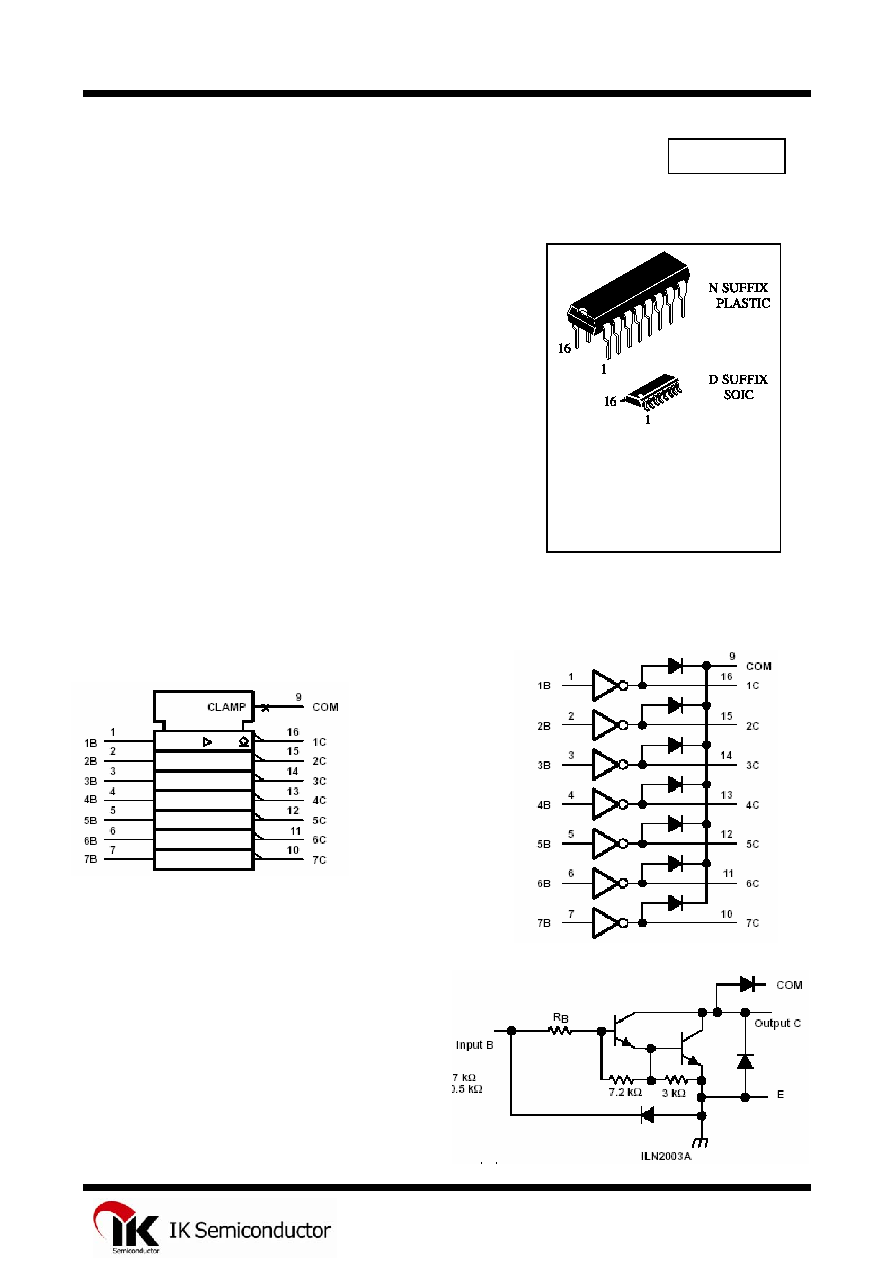
ORDERING INFORMATION
ILN2003AN Plastic
ILN2003AD SOIC
T
A
= -20
úC to 85ú C for all
packages
The ILN2003A has a 2.7-k series base resistor for each
Darlington pair for operation directly with TTL or 5-V CMOS
devices.
500-mA Rated Collector Current (Single Output)
û
û
û
û
û
High-Voltage Outputs . . . 50 V
Output Clamp Diodes
Inputs Compatible With Various Types of Logic
Relay Driver Applications
LOGIC SYSBOL
LOGIC DIAGRAM
SCHEMATICS (each Darlington Pair)
All resistor values shown are nominal.
ILN2003A: R
B
= 2.7 kW
1
ILN2003A
Absolute maximum ratings at 25úC free-air temperature (unless otherwise noted)
Collector-emitter voltage
50 V
Input voltage, V
I
(see Note 1)
30 V Peak
collector current (see Figures 14 and 15)
500 mA
Output clamp current, I
OK
500 mA
Total emitter-terminal current
-2.5 A
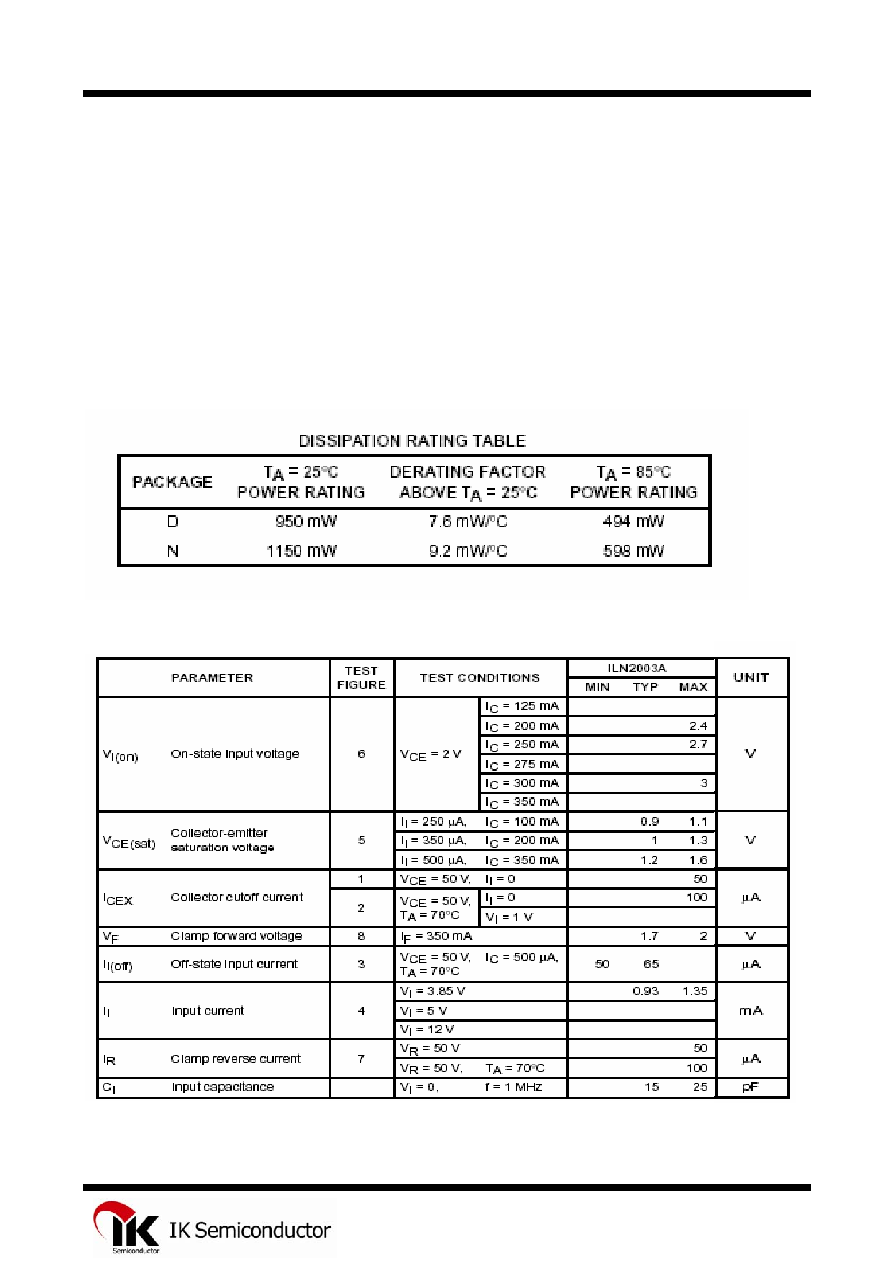
Continuous total power dissipation See Dissipation Rating Table
Operating free-air temperature range, T
A
-20úC to 85úC
Storage temperature range, Tstg
-65úC to 150úC
Lead temperature 1,6 mm (1/16 inch) from case for 10 seconds 260úC
NOTE 1: All voltage values are with respect to the emitter/substrate terminal E, unless otherwise noted.
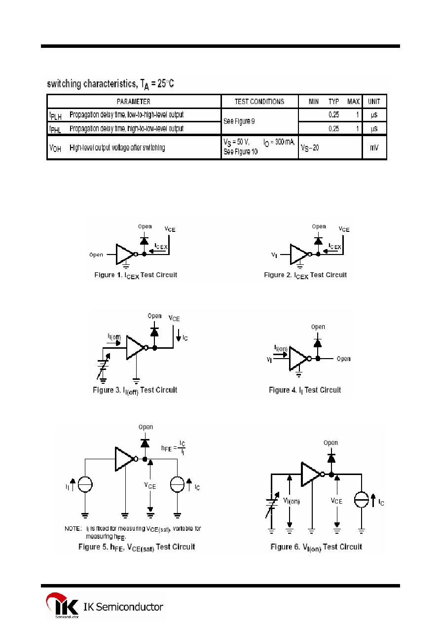
Electrical characteristics, TA = 25úC (unless otherwise noted)
2
ILN2003A
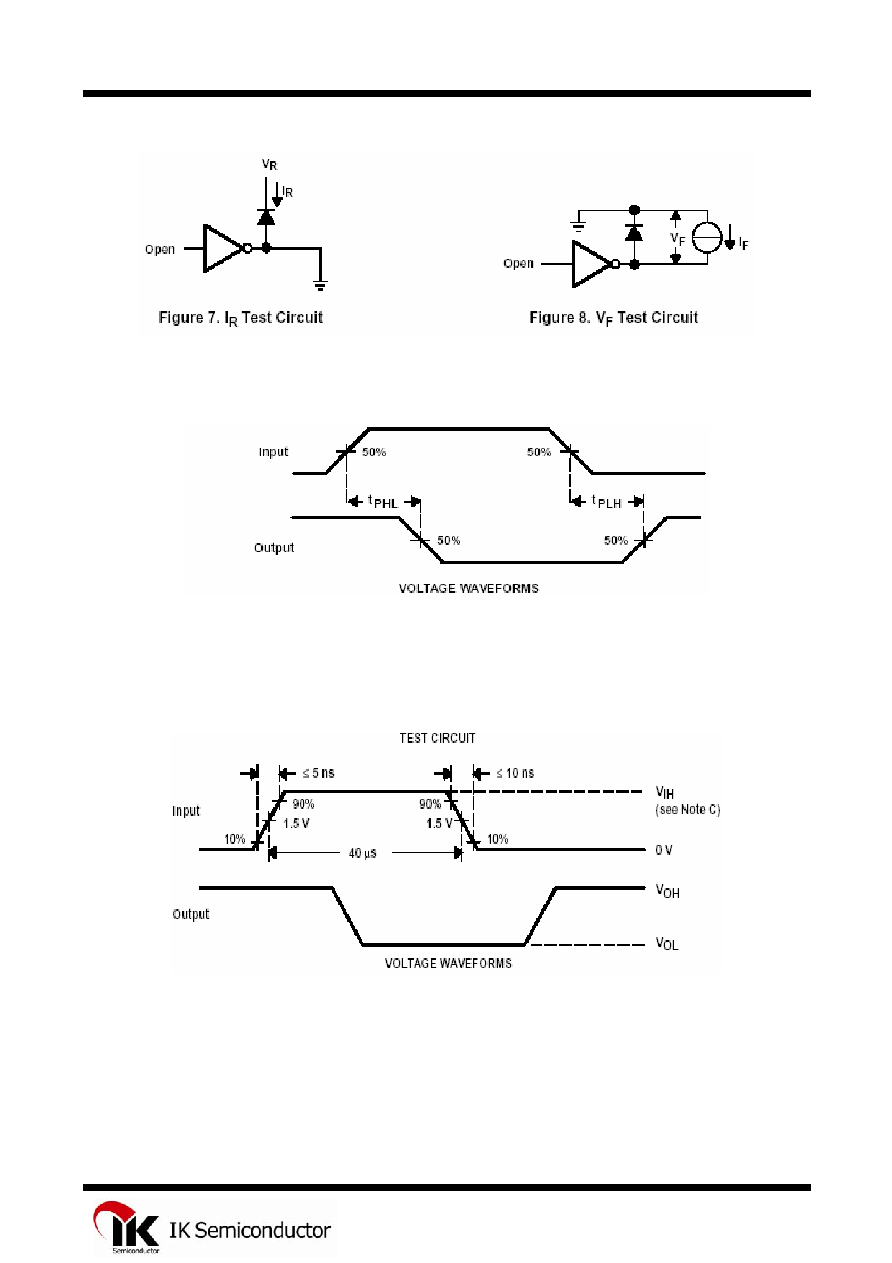
Figure 9. Propagation Delay-Time Waveforms
NOTES: A. The pulse generator has the following characteristics: PRR = 12.5 kHz, Z
O
= 50 .
B. C
L
includes probe and jig capacitance.
C. V
IH
= 3 V;
Figure 10. Latch-Up Test Circuit and Voltage Waveforms
4