 | –≠–ª–µ–∫—Ç—Ä–æ–Ω–Ω—ã–π –∫–æ–º–ø–æ–Ω–µ–Ω—Ç: 82595FX | –°–∫–∞—á–∞—Ç—å:  PDF PDF  ZIP ZIP |
Other brands and names are the property of their respective owners
Information in this document is provided in connection with Intel products Intel assumes no liability whatsoever including infringement of any patent or
copyright for sale and use of Intel products except as provided in Intel's Terms and Conditions of Sale for such products Intel retains the right to make
changes to these specifications at any time without notice Microcomputer Products may have minor variations to this specification known as errata
November 1995
COPYRIGHT
INTEL CORPORATION 1996
Order Number 281732-001
82595FX
ISA BUS HIGH INTEGRATION
ETHERNET CONTROLLER
Y
Optimal Integration for Lowest Cost
Solution
Glueless 8-Bit 16-Bit ISA Bus
Interface
Provides Fully 802 3 Compliant AUI
and TPE Serial Interface
Local SRAM Support up to 64 Kbytes
Integrated ISA Bus Data
Transceivers
FLASH EPROM Boot Support up to
1 Mbyte for Diskless Workstations
Hardware and Software Portable
between Motherboard and Adapter
Card Solutions
Y
High Performance Networking
Functions
Advanced Concurrent Processing of
Receive and Transmit Functions
16-Bit 32-Bit IO Accesses to Local
SRAM with Zero Added Wait-States
Ring Buffer Structure for Continuous
Frame Reception and Transmit
Chaining
Automatic Retransmission on
Collision
Automatically Corrects TPE Polarity
Switching Problems
Auto Negotiation Manual Full Duplex
Support
Y
Low Power CHMOS IV Technology
Y
Ease of Use
Auto-Negotiation of Full Duplex
Functionality
Fully Compatible with ISA Plug and
Play Specification
EEPROM Interface to Support
Jumperless Designs
Software Structures Optimized to
Reduce Processing Steps
Automatically Maps into Unused PC
IO Locations to Help Eliminate LAN
Setup Problems
All Software Structures Contained in
One 16-Byte IO Space
JTAG Port for Reduced Board
Testing Times
Automatic or Manual Switching
between TPE and AUI Ports
Supports Eight IRQs
Y
Power Management
Advanced Power Management
Support by Power Down and Sleep
Mode
Both SL Compatible SMOUT Input
and Non-SL Software Parameter for
Power Down Mode
Y
160-Lead QFP Package Provides
Smallest Available Form Factor
Y
100% Backwards Software Compatible
to 82595TX
281732 ≠ 1
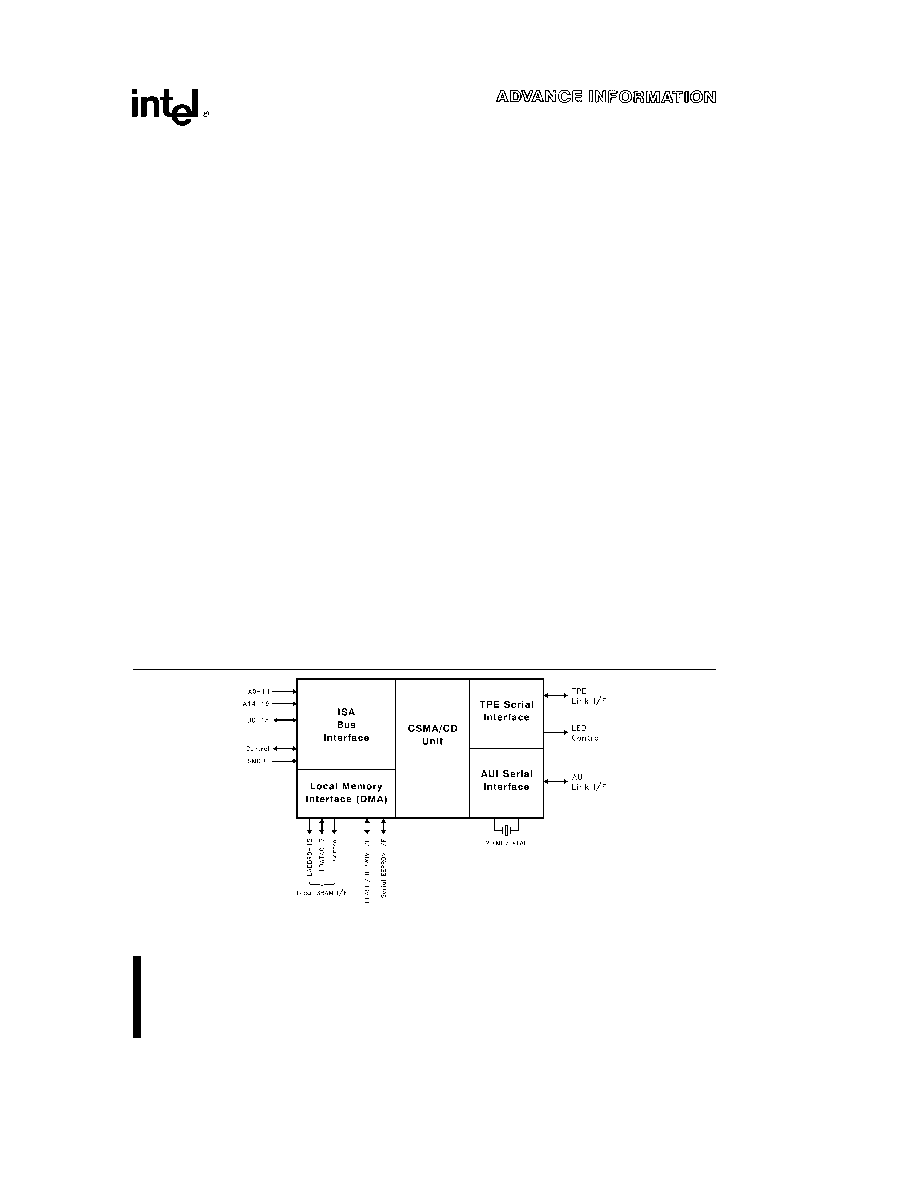
Figure 1 82595FX Block Diagram

82595FX
ISA Bus High Integration ETHERNET Controller
CONTENTS
PAGE
1 0 INTRODUCTION
5
1 1 82595FX Overview
5
1 2 Power Management
5
1 3 Auto-Negotiation
5
1 4 Compliance to Industry
Standards
6
1 4 1 Bus Interface
ISA IEEE
P996
6
1 4 2 ETHERNET Twisted Pair
Ethernet Interface
IEEE 802 3
Specification
6
2 0 82595FX PIN DEFINITIONS
6
2 1 ISA Bus Interface
6
2 2 Local Memory Interface
8
2 3 Miscellaneous Control
9
2 4 JTAG Control
9
2 5 Serial Interface
9
2 6 Serial Interface LEDs
10
2 7 Power and Ground
11
2 8 Reserved Pins
11
2 9 82595FX Pin Summary
12
3 0 82595FX INTERNAL
ARCHITECTURE OVERVIEW
13
3 1 System Interface Overview
13
3 1 1 Concurrent Processing
Functionality
13
3 2 Local Memory Interface
13
3 3 CSMA CD Unit
14
3 4 Serial Interface
14
4 0 ACCESSING THE 82595FX
14
4 1 82595FX Register Map
14
4 1 1 IO Bank 0
15
4 1 2 IO Bank 1
16
4 1 3 IO Bank 2
17
4 2 Writing to the 82595FX
17
4 3 Reading from the 82595FX
18
CONTENTS
PAGE
4 4 Local SRAM Accesses
18
4 4 1 Writing to Local Memory
18
4 4 2 Reading from Local
Memory
18
4 5 Serial EEPROM Interface
19
4 6 Boot EPROM FLASH Interface
20
5 0 COMMAND AND STATUS
INTERFACE
20
5 1 Command OP Code Field
20
5 2 ABORT (Bit 5)
20
5 3 Pointer Field (Bits 6 and 7)
20
5 4 82595FX Status Interface
22
6 0 INITIALIZATION
22
7 0 FRAME TRANSMISSION
23
7 1 82595FX XMT Block Memory
Format
23
7 2 XMT Chaining
25
7 3 Automatic Retransmission on
Collision
28
8 0 FRAME RECEPTION
28
8 1 82595FX RCV Memory
Structure
28
8 2 RCV Ring Buffer Operation
31
9 0 SERIAL INTERFACE
32
10 0 APPLICATION NOTES
33
10 1 Bus Interface
33
10 2 Local Memory Interface
33
10 3 EEPROM Interface (ISA Only)
33
10 4 Serial Interface
33
10 4 1 AUI Circuit
33
10 4 2 TPE Circuit
34
10 4 3 LED Circuit
34
2

CONTENTS
PAGE
10 5 Layout Guidelines
34
10 5 1 General
34
10 5 2 Crystal
34
10 5 3 82595FX Analog Differential
Signals
34
10 5 4 Decoupling
Considerations
34
11 0 ELECTRICAL SPECIFICATIONS
AND TIMINGS
35
11 1 Absolute Maximum Ratings
35
11 1 1 Package Thermal
Specifications
36
CONTENTS
PAGE
11 2 AC Timing Characteristics
36
11 3 AC Measurement Conditions
36
11 4 ISA Interface Timing
37
11 6 Local Memory Timings
41
11 6 1 SRAM Timings
41
11 6 2 FLASH EPROM Timings
43
11 7 Interrupt Timing
45
11 8 RESET and SMOUT Timing
46
11 9 JTAG Timing
47
11 10 Serial Timings
48
3

82595FX
281732 ≠ 2
Figure 2 82595FX Pinout
4

82595FX
1 0
INTRODUCTION
1 1 82595FX Overview
The 82595FX is a highly integrated high perform-
ance LAN controller which provides a cost effective
LAN solution for ISA compatible Personal Computer
(PC) motherboards (both desktop and portable) and
add-on ISA adapter boards The 82595FX integrates
all of the major functions of a buffered LAN solution
into one chip with the exception of the local buffer
memory which is implemented by adding one SRAM
component to the LAN solution The 82595FX's
Concurrent Processing feature significantly enhanc-
es throughput performance Both system bus and
serial link activities occur concurrently allowing the
82595FX to maximize network bandwidth by mini-
mizing delays associated with transmit or receiving
frames The 82595FX's bus interface is a glueless
attachment to an ISA bus Its serial interface pro-
vides a Twisted Pair Ethernet (TPE) and an Attach-
ment Unit Interface (AUI) connection By integrating
the majority of the LAN solution functions into one
cost effective component production cost saving
can be achieved as well as significantly decreasing
the design time for a solution This level of integra-
tion also allows an 82595FX solution to be ported
between different applications (PC motherboards
and adapters while maintaining a compatible hard-
ware and software base
The 82595FX's software interface is optimized to re-
duce the number of processing steps that are re-
quired to interface to the 82595FX solution The
82595FX's initialization and control registers are di-
rectly addressable within one 16-byte IO address
block The 82595FX can automatically resolve any
conflicts to an IO block by moving its IO offset to an
unused location in the case that a conflict occurs
The 82595FX's local memory is arranged in a simple
ring buffer structure for efficient transfer of transmit
and receive packets
The local memory
up to
64 Kbytes of SRAM resides as either a 16-bit or 32-
bit IO port in the host systems IO map programma-
ble through configuration The 82595FX provides di-
rect control over the local SRAM The 82595FX per-
forms a prefetch to the SRAM memory allowing CPU
IO cycles to this data with no added wait-states The
82595FX also provides an interface to up to 1 Mbyte
of FLASH or EPROM memory An interface to an
EEPROM which holds solution configuration values
and can also contain the Node ID allows for the
implementation of a ``jumperless'' design In addi-
tion the 82595FX contains full hardware support for
the implementation of the ISA Plug N' Play specifica-
tion Plug N' Play eliminates jumpers and complicat-
ed setup utilities by allowing peripheral functions to
be added to a PC automatically (such as adapter
cards) without the need to individually configure
each parameter (e g Interrupt IO Address etc)
This allows for configuration ease-of-use which re-
sults in minimal time associated with installation
The 82595FX's packaging and power management
features are designed to consume minimal board
real estate and system power This is required for
applications such as portable PC motherboard de-
signs which require a solution with very low real es-
tate and power consumption The 82595FX package
is a 160-lead PQFP (Plastic Quad Flat Pack) Its di-
mensions are 28 mm by 28 mm and 3 5 mm in
height The 82595FX contains two power down
modes an SL compatible power down mode which
utilizes the SL SMOUT input and a POWER DOWN
command for non-SL systems
1 2 Power Management
Power management and low power consumption are
two items that will allow any design using the
82595FX to be suitable for green PC use Low pow-
er operation is initiated when software issues a
SLEEP command to the device After a short wait it
will shut off the system clock some parts of the
Backoff Randomizer several input buffers and the
two LED drivers The 82595FX will subsequently
wake up from sleep mode when software initiates an
ISA cycle in the application as well as when it re-
ceives a frame addressed to it The total power con-
sumption when in sleep mode can be as low as ap-
proximately 175 mW Normal idle power consump-
tion is 300 mW
The software POWER DOWN command along with
its
companion
hardware
implementation
the
SMOUT I O pin provide additional power manage-
ment capabilities This feature allows the 82595FX
to be powered down and then at some time in the
future be selectively reset without having lost the
current configuration
See the 82595FX User's
Guide for further details on these features
1 3 Auto-Negotiation
Auto-negotiation functionality is a method of auto-
matically determining the highest common operating
mode (i e
10BaseT half duplex 10BaseT full du-
plex etc ) between two network devices Using this
functionality two stations each having a varying
number of different operating modes negotiate the
highest possible common operating mode between
them During the power up sequence the auto-ne-
gotiation functionality will automatically establish a
link with which it can take advantage of any auto-ne-
gotiation-capable device it is connected to An auto-
negotiation capable hub can detect and automatical-
ly configure its ports to take maximum advantage of
5