 | –≠–Ľ–Ķ–ļ—ā—Ä–ĺ–Ĺ–Ĺ—č–Ļ –ļ–ĺ–ľ–Ņ–ĺ–Ĺ–Ķ–Ĺ—ā: 840 | –°–ļ–į—á–į—ā—Ć:  PDF PDF  ZIP ZIP |

Intel
ģ
840 Chipset: 82840 Memory Controller
Hub (MCH)
Datasheet
September 2000
Document Number:
298020-002
R

2
Datasheet
Information in this document is provided in connection with Intel products. No license, express or implied, by estoppel or otherwise, to any intellectual
property rights is granted by this document. Except as provided in Intel's Terms and Conditions of Sale for such products, Intel assumes no liability
whatsoever, and Intel disclaims any express or implied warranty, relating to sale and/or use of Intel products including liability or warranties relating to fitness
for a particular purpose, merchantability, or infringement of any patent, copyright or other intellectual property right. Intel products are not intended for use in
medical, life saving, or life sustaining applications.
Intel may make changes to specifications and product descriptions at any time, without notice.
Designers must not rely on the absence or characteristics of any features or instructions marked "reserved" or "undefined." Intel reserves these for future
definition and shall have no responsibility whatsoever for conflicts or incompatibilities arising from future changes to them.
The Intelģ 82840 MCH may contain design defects or errors known as errata which may cause the product to deviate from published specifications. Current
characterized errata are available on request.
Contact your local Intel sales office or your distributor to obtain the latest specifications and before placing your product order.
I
2
C is a 2-wire communications bus/protocol developed by Philips. SMBus is a subset of the I
2
C bus/protocol and was developed by Intel. Implementations
of the I
2
C bus/protocol may require licenses from various entities, including Philips Electronics N.V. and North American Philips Corporation.
Alert on LAN is a result of the Intel-IBM Advanced Manageability Alliance and a trademark of IBM
Copies of documents which have an ordering number and are referenced in this document, or other Intel literature, may be obtained from:
Intel Corporation
www.intel.com
or call 1-800-548-4725
*Third-party brands and names are the property of their respective owners.
Copyright © Intel Corporation 2000

82840
MCH
R
Datasheet
3
Contents
1. Overview.....................................................................................................................................13
1.1. Intel
ģ
840 Chipset System Architecture .........................................................................13
1.2.
82840 MCH Overview ....................................................................................................16
1.3. Terminology ...................................................................................................................18
2. Signal
Description.......................................................................................................................21
2.1.
Host Interface Signals ....................................................................................................22
2.2.
Direct Rambus* Interface A ...........................................................................................24
2.3.
Direct Rambus* Interface B ...........................................................................................25
2.4.
Hub Interface A Signals .................................................................................................26
2.5.
Hub interface B Signals..................................................................................................26
2.6.
AGP Interface Signals....................................................................................................26
2.6.1. AGP Addressing Signals ...................................................................................26
2.6.2. AGP Flow Control Signals .................................................................................27
2.6.3. AGP Status Signals ...........................................................................................28
2.6.4. AGP Clocking Signals--Strobes .......................................................................28
2.6.5. AGP FRAME# Signals.......................................................................................29
2.7.
Clocks, Reset, and Miscellaneous .................................................................................31
2.8.
Voltage References, PLL Power ....................................................................................32
2.9. Strap
Signals..................................................................................................................33
3. Register
Description ...................................................................................................................35
3.1.
Register Nomenclature and Access Attributes ..............................................................35
3.2.
PCI Configuration Space Access...................................................................................36
3.3.
I/O Mapped Registers ....................................................................................................39
3.3.1. CONF_ADDR
Configuration Address Register ..............................................39
3.3.2. CONF_DATA--Configuration Data Register.....................................................40
3.4.
Host-Hub interface A Bridge/DRAM Controller Device Registers (Device 0) ................41
3.4.1. VID--Vendor Identification Register (Device 0) ................................................44
3.4.2. DID--Device Identification Register (Device 0).................................................44
3.4.3. PCICMD--PCI Command Register (Device 0) .................................................45
3.4.4. PCISTS--PCI Status Register (Device 0).........................................................46
3.4.5. RID--Revision Identification Register (Device 0)..............................................47
3.4.6. SUBC--Sub-Class Code Register (Device 0)...................................................47
3.4.7. BCC--Base Class Code Register (Device 0)....................................................47
3.4.8. MLT--Master Latency Timer Register (Device 0).............................................48
3.4.9. HDR--Header Type Register (Device 0) ..........................................................48
3.4.10. --Aperture Base Configuration Register (Device 0)..........................................48
3.4.11. SVID--Subsystem Vendor ID (Device 0) ..........................................................50
3.4.12. SID--Subsystem ID (Device 0) .........................................................................50
3.4.13. CAPPTR--Capabilities Pointer (Device 0)........................................................50
3.4.14. GAR[15:0]--RDRAM Group Architecture Register (Device 0)..........................51
3.4.15. MCHCFG--MCH Configuration Register (Device 0).........................................52
3.4.16. FDHC--Fixed DRAM Hole Control Register (Device 0)....................................53
3.4.17. PAM0≠PAM6--Programmable Attribute Map Registers (Device 0) ................54
3.4.18. GBA0≠GBA15--RDRAM Group Boundary Address Register (Device 0) ........57
3.4.19. RDPS--RDRAM Pool Sizing Register (Device 0) .............................................58

4
Datasheet
3.4.20. DRD--RDRAM Device Register Data Register (Device 0) .............................. 59
3.4.21. RICM--RDRAM Initialization Control Management Register (Device 0).......... 59
3.4.22. MCH Expansion RAC A/B Configuration Registers .......................................... 61
3.4.23. SMRAM--System Management RAM Control Register (Device 0) ................ 61
3.4.24. ESMRAMC--Extended System Management RAM Control Register
(Device 0) .......................................................................................................... 62
3.4.25. ACAPID--AGP Capability Identifier Register (Device 0) .................................. 63
3.4.26. AGPSTAT--AGP Status Register (Device 0)................................................... 64
3.4.27. AGPCMD--AGP Command Register (Device 0) ............................................. 65
3.4.28. AGPCTRL--AGP Control Register (Device 0) ................................................. 66
3.4.29. APSIZE--Aperture Size (Device 0) .................................................................. 66
3.4.30. ATTBASE
Aperture Translation Table Base Register (Device 0) ................ 67
3.4.31. AMTT--AGP Interface Multi-Transaction Timer Register (Device 0) .............. 67
3.4.32. LPTT--Low Priority Transaction Timer Register (Device 0)............................. 68
3.4.33. RDTR--RDRAM Timing Register (Device 0) ................................................... 69
3.4.34. RDCR--RDRAM Refresh Control Register (Device 0)..................................... 70
3.4.35. TOM--Top of Low Memory Register (Device 0)............................................... 71
3.4.36. ERRSTS--Error Status Register (Device 0)..................................................... 71
3.4.37. ERRCMD--Error Command Register (Device 0) ............................................. 73
3.4.38. SMICMD--SMI Command Register (Device 0)................................................ 75
3.4.39. SCICMD--SCI Command Register (Device 0)................................................. 77
3.4.40. SKPD--Scratchpad Data (Device 0) ................................................................ 78
3.4.41. HERRCTL_STS--Host Error Control/Status Register (Device 0) .................... 79
3.4.42. DERRCTL_STS--DRAM Error Control/Status Register (Device 0) ................ 80
3.4.43. EAP--Error Address Pointer Register (Device 0)............................................. 80
3.4.44. AGPBCTRL--AGP Buffer Strength Control Register ....................................... 81
3.4.45. AGPAPPEND--AGP Append Disable Register................................................ 81
3.4.46. GTLNCLAMP--GTL N Clamp Disable Register............................................... 81
3.5.
AGP Bridge Registers (Device 1) .................................................................................. 82
3.5.1. VID1--Vendor Identification Register (Device 1).............................................. 83
3.5.2. DID1--Device Identification Register (Device 1) .............................................. 83
3.5.3. PCICMD1--PCI-PCI Command Register (Device 1) ....................................... 84
3.5.4. PCISTS1--PCI-PCI Status Register (Device 1) ............................................... 85
3.5.5. RID1--Revision Identification Register (Device 1) ........................................... 85
3.5.6. SUBC1--Sub-Class Code Register (Device 1) ................................................ 86
3.5.7. BCC1--Base Class Code Register (Device 1) ................................................. 86
3.5.8. MLT1--Master Latency Timer Register (Device 1) .......................................... 86
3.5.9. HDR1--Header Type Register (Device 1) ........................................................ 86
3.5.10. PBUSN1--Primary Bus Number Register (Device 1)....................................... 87
3.5.11. SBUSN1--Secondary Bus Number Register (Device 1) .................................. 87
3.5.12. SUBUSN1--Subordinate Bus Number Register (Device 1) ............................. 87
3.5.13. SMLT1--Secondary Master Latency Timer Register (Device 1)...................... 88
3.5.14. IOBASE1--I/O Base Address Register (Device 1)........................................... 88
3.5.15. IOLIMIT1--I/O Limit Address Register (Device 1)............................................ 89
3.5.16. SSTS1--Secondary PCI-PCI Status Register (Device 1)................................. 89
3.5.17. MBASE1--Memory Base Address Register (Device 1).................................... 90
3.5.18. MLIMIT1--Memory Limit Address Register (Device 1) .................................... 91
3.5.19. PMBASE1--Prefetchable Memory Base Address Register (Device 1)............ 91
3.5.20. PMLIMIT1--Prefetchable Memory Limit Address Register (Device 1)............. 92
3.5.21. BCTRL1--PCI-PCI Bridge Control Register (Device 1) ................................... 92
3.5.22. ERRCMD1--Error Command Register (Device 1) ........................................... 94

82840
MCH
R
Datasheet
5
3.6.
Hub interface B Bridge Registers (Device 2) .................................................................95
3.6.1. VID2--Vendor Identification Register (Device 2) ..............................................96
3.6.2. DID2--Device Identification Register (Device 2)...............................................96
3.6.3. PCICMD2--PCI-PCI Command Register (Device 2)........................................97
3.6.4. PCISTS2--PCI-PCI Status Register (Device 2)................................................98
3.6.5. RID2--Revision Identification Register (Device 2)............................................98
3.6.6. SUBC2--Sub-Class Code Register (Device 2).................................................99
3.6.7. BCC2--Base Class Code Register (Device 2)..................................................99
3.6.8. MLT2--Master Latency Timer Register (Device 2)...........................................99
3.6.9. HDR2--Header Type Register (Device 2) ........................................................99
3.6.10. PBUSN2--Primary Bus Number Register (Device 2) .....................................100
3.6.11. SBUSN2--Secondary Bus Number Register (Device 2) ................................100
3.6.12. SUBUSN2--Subordinate Bus Number Register (Device 2)............................100
3.6.13. SMLT2--Secondary Master Latency Timer Register (Device 2) ....................100
3.6.14. IOBASE2--I/O Base Address Register (Device 2) .........................................101
3.6.15. IOLIMIT2--I/O Limit Address Register (Device 2) ..........................................101
3.6.16. SSTS2--Secondary PCI-PCI Status Register (Device 2) ...............................102
3.6.17. MBASE2--Memory Base Address Register (Device 2) ..................................103
3.6.18. MLIMIT2--Memory Limit Address Register (Device 2)...................................103
3.6.19. PMBASE2--Prefetchable Memory Base Address Register (Device 2) ..........104
3.6.20. PMLIMIT2--Prefetchable Memory Limit Address Register (Device 2) ...........104
3.6.21. BCTRL2--PCI-PCI Bridge Control Register (Device 2) ..................................105
3.6.22. ERRCMD2--Error Command Register (Device 2) .........................................106
4.
System Address Map................................................................................................................107
4.1.
Memory Address Ranges.............................................................................................107
4.1.1. DOS Compatibility Area...................................................................................108
4.1.2. Extended Memory Area...................................................................................110
4.1.3. AGP Memory Address Ranges .......................................................................112
4.1.4. AGP DRAM Graphics Aperture .......................................................................113
4.1.5. System Management Mode (SMM) Memory Range .......................................113
4.1.5.1. SMM Space Definition.......................................................................114
4.1.5.2. SMM Space Restrictions ...................................................................114
4.1.6. Memory
Shadowing.........................................................................................115
4.1.7. I/O Address Space ..........................................................................................115
4.1.7.1. AGP I/O Address Mapping................................................................115
4.1.8. MCH Decode Rules and Cross-Bridge Address Mapping...............................116
4.1.8.1. The Hub interface A Decode Rules...................................................116
4.1.8.2. The Hub interface B Decode Rules...................................................116
4.1.8.3. AGP Interface Decode Rules ............................................................117
4.1.8.4. Legacy VGA Ranges.........................................................................118

6
Datasheet
5. Functional
Description.............................................................................................................. 119
5.1. Host
Interface .............................................................................................................. 119
5.1.1. Frame Buffer Memory Support ....................................................................... 125
5.2. AGP
Interface .............................................................................................................. 125
5.2.1. AGP Target Operations .................................................................................. 125
5.2.2. AGP Transaction Ordering ............................................................................. 127
5.2.3. AGP
Electricals ............................................................................................... 127
5.2.4. The Differences Between AGP FRAME# and PCI-66 Devices ...................... 127
5.2.5. 4x AGP Protocol ............................................................................................. 127
5.2.6. Fast
Writes...................................................................................................... 128
5.2.7. AGP Universal Connector............................................................................... 128
5.2.8. AGP FRAME# Transactions on AGP ............................................................. 128
5.2.8.1. MCH Initiator and Target Operations................................................ 129
5.2.8.2. MCH Retry/Disconnect Conditions ................................................... 131
5.2.8.3. Delayed Transaction......................................................................... 131
5.3. RDRAM
Interface ........................................................................................................ 132
5.3.1. RDRAM Organization and Configuration ........................................................ 134
5.3.1.1. Rules for Populating RDRAM Devices ............................................. 135
5.3.1.2. RDRAM CMOS Signals Description and Usage............................... 136
5.3.1.3. Direct RDRAM Core Refresh............................................................ 138
5.3.1.4. Direct RDRAM Current Calibration ................................................... 138
5.3.2. Direct RDRAM Command Encoding............................................................... 138
5.3.2.1. Row Packet (ROWA/ROWR) ........................................................... 139
5.3.2.2. Column Packet (COLC/COLX) ......................................................... 141
5.3.2.3. Data Packet ...................................................................................... 142
5.3.3. Direct RDRAM Register Programming ........................................................... 143
5.3.4. Direct RDRAM Operating States .................................................................... 143
5.3.5. RDRAM Power Management.......................................................................... 144
5.3.6. Data
Integrity................................................................................................... 145
5.3.7. RDRAM Array Thermal Management............................................................. 145
5.4. System
Reset .............................................................................................................. 146
6.
Ballout and Package Information ............................................................................................. 147
6.1.
MCH Ball List ............................................................................................................... 147
6.2. Package
Information.................................................................................................... 154
6.2.1. 82840 RSL Nomalized Trace Length Data ..................................................... 156
6.3. Initialization
Sequence................................................................................................. 160
6.4. XOR
Chains................................................................................................................. 161

82840
MCH
R
Datasheet
7
Figures
Figure 1. Intel
840 Chipset System Block Diagram ................................................................14
Figure 2. PAM Registers...........................................................................................................55
Figure 3. System Address Map ..............................................................................................107
Figure 4. Detailed DOS Compatible Area Address Map.........................................................110
Figure 5. Detailed Extended Memory Range Address Map ...................................................110
Figure 6. Single Channel-pair Mode .......................................................................................132
Figure 7. Multiple Channel-pair Mode.....................................................................................133
Figure 8. RDRAM Devices Sideband CMOS Signal Configuration on
Rambus* Channel A ................................................................................................136
Figure 9. MRH-R Sideband CMOS Signal Configuration on Rambus* Channel A.................137
Figure 10. 82840 MCH Reset .................................................................................................146
Figure 11. MCH Ballout (Top View, Left Side)........................................................................148
Figure 12. MCH Ballout (Top View, Right Side) .....................................................................149
Figure 13. 82840 MCH BGA Package Dimensions (Top and Side Views) ............................154
Figure 14. 82840 MCH BGA Package Dimensions (Bottom View) ........................................155
Figure 15. XOR-Tree Chain....................................................................................................159
Figure 16. XOR Chain Test Mode Initialization.......................................................................160

8
Datasheet
Tables
Table 1. Maximum Memory Vs DRAM Densities ..................................................................... 17
Table 2. MCH Configuration Space (Device 0) ........................................................................ 41
Table 3. Attribute Bit Assignment............................................................................................. 54
Table 4. PAM Registers and Associated Memory Segments .................................................. 55
Table 5. MCH Configuration Space (Device 1) ........................................................................ 82
Table 6. MCH Configuration Space (Device 2) ........................................................................ 95
Table 7. Memory Segments and their Attributes.................................................................... 108
Table 8. P6 Bus Transactions Supported by the MCH .......................................................... 119
Table 9. Types of Responses Supported by the MCH........................................................... 121
Table 10. Types of Special Cycles Supported by the MCH ................................................... 124
Table 11. AGP Commands Supported by the MCH When Acting as an AGP Target ........... 126
Table 12. Fast Write Register Programming ......................................................................... 128
Table 13. PCI Commands Supported by the MCH When Acting as A FRAME# Target ....... 129
Table 14. Maximum Memory Supported For Various Configurations .................................... 133
Table 15. Direct RDRAM Device Configurations ................................................................... 134
Table 16. RDRAM Device Grouping ...................................................................................... 135
Table 17. Sideband CMOS Signal Description ...................................................................... 137
Table 18. CMD Signal Value Decode..................................................................................... 137
Table 19. ROWA Packet for Activating (sensing) a Row (i.e., AV = 1).................................. 139
Table 20. ROWR Packet for other operations (i.e., AV = 0) .................................................. 139
Table 21. COLC Packet ......................................................................................................... 141
Table 22. COLC Packet Field Encodings............................................................................... 141
Table 23. COLX Packet (M = 0)............................................................................................. 142
Table 24. COLM Packet and COLX Packet Field Encodings ................................................ 142
Table 25. Data Packet............................................................................................................ 142
Table 26. DRAM Operating States......................................................................................... 143
Table 27. RDRAM Power Management States...................................................................... 144
Table 28. MCH Alphabetical Ballout List ................................................................................ 150
Table 29. Package Dimensions ............................................................................................. 155
Table 30. XOR Chain #0 Connections ................................................................................... 161
Table 31. XOR Chain #1 Connections ................................................................................... 161
Table 32. XOR Chain #2 Connections ................................................................................... 162
Table 33. XOR Chain #3 Connections ................................................................................... 162
Table 34. XOR Chain #4 Connections ................................................................................... 163
Table 35. XOR Chain #5 Connections ................................................................................... 164
Table 36. XOR Chain #6 Connections ................................................................................... 164

82840
MCH
R
Datasheet
9
Revision History
Rev. Draft/Changes
Date
-001
∑
Initial Release
October 1999
-002
∑
Minor edits throughout for clarity.
∑
Removed references to MRH-S and SDRAM
∑
Removed references to using two MRH-Rs per channel.
September 2000

10
Datasheet
This page is left intentionally blank.

82840
MCH
R
Datasheet
11
Intel
ģ
82840 MCH
Product Features
!
Processor/Host Bus Support
Supports up to two Pentium
II processors
or Pentium
III
processors at 100 MHz or
133 MHz system bus frequency
Supports full symmetric multiprocessor
(SMP) protocol
Supports 32- or 36-bit host bus addressing
Supports 8 deep In-Order Queue
ECC protection on FSB data signals
IERR and BERR signals generate SCI/SERR
Parity protection on address/response signals
!
Memory Controller--Direct Rambus* Support
Direct support for dual Direct Rambus*
Channels operating in lock-step: Supports
300 MHz, 400 MHz
Supports 64Mb, 128Mb, 256Mb RDRAM
devices
Maximum memory array size up to 1 GB
using 64Mb, 2 GB using 128Mb, 4 GB using
256Mb
Supports up to 64 Direct Rambus* devices
without using MRH-Rs
Supports up to four Rambus* channels using
two external Memory Repeater Hubs for
RDRAM devices (MRH-R)
!
Power Management
SMRAM space remapping to
A0000h≠BFFFFh (128 KB)
Supports extended SMRAM space above
256 MB, additional 128 KB / 256 KB /
512 KB / 1 MB TSEG from Top of
Memory, cacheable (cacheability controlled
by processor)
Suspend to RAM support
!
Memory Controller--Configurable Optional
ECC Operation
ECC with single bit Error Correction and
multiple bit Error Detection
Single bit errors corrected and written back
to memory (scrubbing)
!
Accelerated Graphics Port (AGP) Interface
Supports a single AGP device (either via a
connector or on the motherboard)
Supports AGP 2.0 including 4x AGP data
transfers and 2x/4x Fast Write protocol
AGP Universal Connector support via dual
mode buffers to allow AGP 2.0 3.3V or 1.5V
signaling
!
Hub interface A to ICH--High speed
interconnect between MCH and ICH
(266 MB/sec)
!
Hub interface B to P64H--High speed
interconnect between MCH and P64H
(533 MB/sec)
!
Arbitration
Distributed arbitration model for optimum
concurrency support
Concurrent operations of host, hub interface,
AGP, and memory buses supported via
dedicated arbitration and data buffering logic
!
Process/Package
544 mBGA
The Intel
82840 Memory Controller Hub may contain design defects or errors known as errata which
may cause the product to deviate from published specifications. Current characterized errata are available
on request.

12
Datasheet
Simplified Block Diagram
MCH_blk.vsd
HA[35:3]#
HD[63:0]#
ADS#
BNR#
BPRI#
AP[1:0]#
BERR#
BREQ0#
DBSY#
DEP[7:0]#
DEFER#
DRDY#
HIT#
HITM#
HLOCK#
HREQ[4:0]#
HTRDY#
IERR#
RP#
RSP#
RS[2:0]#
CPURST#
System Bus
Interface
AGP
Interface
Clocks,
Reset, and
Test
CPUCLK
CLK66
RCLKOUT[A:B]
HCLKOUT[A:B]
RSTIN#
TEST#
OVERT#
Voltage
References,
Power,
Ground
GTLREF[A:B]
AGPRCOMP
CHA_REF[1:0]
CHB_REF[1:0]
AGPREF
HLAREF
HLBREF
VDDQ
VCC1_8
VTT
VSS
PIPE#
SBA[7:0]
ST[2:0]
RBF#
WBF#
AD_STB0, AD_STB0#
AD_STB1, AD_STB1#
SB_STB, SB_STB#
G_AD[31:0]
G_C/BE[3:0]#
G_FRAME#
G_TRDY#
G_IRDY#
G_REQ#
G_DEVSEL#
G_GNT#
G_PAR
G_STOP#
G_SERR#
HLA[11:0]
HLA_STB, HLA_STB#
HLAZCOMP
Hub
Interface
A
HLB[19:0]
HLB_STB[1:0], HLB_STB[1
HLBRCOMP
Hub
Interface
B
CHA_DQA[8:0]
CHA_DQB[8:0]
CHA_RQ[7:5] or CHA_ROW[2:0]
CHA_RQ[4:0] or CHA_COL[4:0]
CHA_CTM, CHA_CTM#
CHA_CFM, CHA_CFM#
CHA_CMD
CHA_SCK
CHA_SIO
CHA_EXP[1:0]
System
Memory
Direct
Rambus
Interface
A
CHB_DQA[8:0]
CHB_DQB[8:0]
CHB_RQ[7:5] or CHB_ROW[2:0]
CHB_RQ[4:0] or CHB_COL[4:0]
CHB_CTM, CHB_CTM#
CHB_CFM, CHB_CFM#
CHB_CMD
CHB_SCK
CHB_SIO
CHB_EXP[1:0]
System
Memory
Direct
Rambus
Interface
B

82840
MCH
R
Datasheet
13
1. Overview
The Intel
ģ
840 chipset is a high-bandwidth chipset designed for workstation and server platforms based
on Intel
Pentium
II processor / Intel
Pentium
III
processor architectures. The chipset contains two
main components and additional optional components that provide expansion capability. The 82840
Memory Controller Hub (MCH) provides the system bus interface, memory controller, AGP interface,
hub interface for I/O, and hub interface for PCI bus expansion. This document describes the 82840
Memory Controller Hub (MCH). Section 1.1, Intel
ģ
840 Chipset System Architecture, provides an
overview of each of the components of the Intel
ģ
840 chipset.
1.1. Intel
ģ
840 Chipset System Architecture
The Intel
ģ
840 chipset is optimized for the Intel
Pentium
II processor and Intel
Pentium
III
processor
architectures. The Intel
ģ
840 chipset allows flexibility for dual and multi-processor configurations with
100 MHz and 133 MHz system buses. The Intel
ģ
840 chipset consists of 2 main components: 82840
Memory Controller Hub (MCH), and 82801AA I/O Controller Hub (ICH).
Architectural expansion is provided with the memory expansion card and PCI 64-bit Hub. The 82803AA
Memory Repeater Hub (MRH-R) provides memory expansion capabilities for RDRAM channels. The
82806AA PCI 64 Hub (P64H) provides PCI bridging functions between the hub interface and PCI Bus.
The Intel
ģ
840 chipset components are interconnected via an interface called "hub interface". The hub
interface provides efficient communication between the chipset components.
Additional hardware platform features, supported by Intel
ģ
840 chipset, include AGP 4X, RDRAM,
Ultra DMA/66, Low Pin Count interface (LPC), and Universal Serial Bus (USB). The Intel
ģ
840 chipset
architecture removes the requirement for the ISA expansion bus that was traditionally integrated into the
I/O subsystem of PCIsets/AGPsets. This eliminates many conflicts experienced when installing legacy
ISA hardware and drivers.
The Intel
ģ
840 chipset is also ACPI compliant and supports Full-on, Stop Grant, Suspend to RAM,
Suspend to Disk, and Soft-off power management states. Through the use of an appropriate LAN device,
Intel
ģ
840 chipset also supports wake-on-LAN
*
for remote administration and troubleshooting.

14
Datasheet
Figure 1. Intel
840 Chipset System Block Diagram
Main Memory
(2 GB Max.)
sys_blk
82840 Memory
Controller Hub
(MCH)
AGP 4X
Graphics
Controller
Hub
Interface A
AGP 2.0
Processor
Processor
82806AA
PCI 64 Hub
(P64H)
Six 33 MHz
PCI Slots
Or
Two 66 MHz
PCI Slots
82801AA
I/O Controller
Hub (ICH)
FWH Flash
BIOS
GPIO
2 USB Ports
4 IDE Drives
AC'97 Codec(s)
(optional)
AC'97 2.1
33 MHz
PCI Bus
PCI
Slots
PCI
Agent
LPC I/F
Super I/O
RDRAM
RDRAM
Channel A
Channel B
Memory Interface
(300 MHz, 400 MHz)
Hub
Interface B
RDRAM
82803AA
(MRH-R)
RDRAM
RDRAM
82803AA
(MRH-R)
RDRAM
Channel A
Channel B
Memory Expansion Card
Shaded blocks are
Intel
ģ
840 Chipset components
82801AA I/O Controller Hub (ICH)
The ICH is a highly integrated multifunctional I/O Controller Hub that provides the interface to the PCI
Bus and integrates many of the functions needed in today's PC platforms. The MCH and ICH
communicate over a dedicated hub interface. Functions and capabilities include:
∑ PCI Rev 2.2 compliant with support for 33 MHz PCI operations
∑ Supports up to 6 Req/Gnt pairs (PCI Slots)
∑ Power Management Logic Support
∑ Enhanced DMA Controller, Interrupt Controller and Timer Functions
∑ Integrated IDE controller; Ultra ATA/66
∑ USB host interface with support for 2 USB ports
∑ System Management Bus (SMBus) compatible with most I
2
C devices
∑ AC'97 2.1 Compliant Link for Audio and Telephony CODECs
∑ Low Pin Count (LPC) interface
∑ FWH Flash BIOS interface support
∑ Alert on LAN*

82840
MCH
R
Datasheet
15
82806AA PCI 64 Hub (P64H)
The PCI-64 Hub(P64H) is a peripheral chip that performs PCI bridging functions between the hub
interface and the PCI Bus and is used as an integral part of the Intel
840 chipset. The P64H has a 16-bit
primary hub interface to the Memory Controller Hub (MCH) and a secondary 64-bit PCI Bus interface.
The 64-bit interfaces inter-operates transparently with either 64-bit or 32-bit devices. The P64H is fully
compliant with the PCI Local Bus Specification, Revision 2.2. The P64H functions include:
∑ PCI Hot Plug controller
∑ Integrated PCI low skew clock driver
∑ I/O APIC
82803AA Memory Repeater Hub (MRH-R)
The MRH-R supports multiple RDRAM channels from an "expansion channel." Expansion channel is
the interconnect between the MCH and the MRH-R. Each MRH-R can support up to 2 "stick" channels.
The MRH-R acts as a pass-through logic with fixed delay for read and write accesses from expansion
channels to RDRAM channels. The MRH-R features include:
∑ Maximum of 1 GB memory per channel
∑ Nap Entry/Exit, Power down Exit, Refresh and Precharge on a channel upon request from memory
controller
∑ Core logic gating to minimize power consumption
∑ Clock generation for Direct Rambus* Clock Generator (DRCG)
∑ Integrated SMBus controller to read/write data from/to SPD EEPROM on the RIMMs

16
Datasheet
1.2.
82840 MCH Overview
The 82840 Memory Hub (MCH) component provides the processor interface, DRAM interface, and
AGP interface in a 82840 workstation or server platform. It supports dual channels of Direct Rambus
DRAM operating in lock-step. It also supports 4x AGP data transfers and 2x/4x AGP Fast Writes. The
MCH contains advanced power management logic. The Intel 840 chipset platform uses the dedicated I/O
Controller Hub (ICH) designed for use with the MCH to provide the features required by a workstation
or a server platform. In addition, the 82840 MCH implements a second 16 bit/66 MHz port that may be
used to connect an advanced 64 bit PCI interface (P64H). Communication with ICH and P64H is
accomplished via a high speed interface called "hub interface".
The 82840 MCH contains the following functionality:
∑ Supports up to two processor configurations at 100 MHz or 133 MHz
∑ GTL+ host bus supporting 32 or 36-bit host addressing
∑ Dual Direct Rambus channels supported for 300 MHz or 400 MHz operation
∑ 4 GB support for RDRAM devices
∑ AGP interface with 4x SBA/Data Transfer and 2x/4x Fast Write capability
∑ 8 bit, 66 MHz hub interface A to ICH
∑ 16 bit, 66 MHz hub interface B to P64H
∑ Fully optimized data paths and buffering
∑ Distributed arbitration for highly concurrent operation
Host Interface
The 82840 MCH supports up to two processors at FSB frequencies of 100/133 MHz using AGTL+
signaling. In a dual-processor system one of the two processor agent IDs must be assigned to ID0. The
82840 MCH supports either 32 or 36-bit host addresses, allowing the processor to access the entire 4 GB
of the MCH's memory address space. The MCH has an 8-deep In-Order Queue to support up to eight
outstanding pipelined address requests on the host bus. Host-initiated I/O cycles are positively decoded
to AGP, hub interface B, or MCH configuration space and subtractively decoded to hub interface A.
Host-initiated memory cycles are positively decoded to AGP, hub interface B, or DRAM, and are again
subtractively decoded to hub interface A. AGP semantic memory accesses initiated from AGP to DRAM
are not snooped on the host bus. Memory accesses initiated from AGP using PCI semantics and from
either hub interface to DRAM will be snooped on the FSB. Memory accesses whose addresses lie within
the AGP aperture are translated using the AGP address translation table, regardless of the originating
interface.
The MCH provides optional host bus error checking for data, address, request and response signals.
Single bit errors (correctable) are always corrected if it is enabled and can be configured to generate hub
interface SMI or SCI cycles to ICH on the host data bus. Multiple bit errors (uncorrectable) can be
configured to generate a BERR# condition on the host bus. The MCH can be configured to generate hub
interface SERR or SCI cycles to ICH for BERR# or IERR# error conditions. The MCH can also generate
the hub interface SERR cycle to ICH for the host address parity or the request parity conditions. The
MCH also supports response parity RSP# for the response signals RS[2:0]#.
82840
MCH
R
Datasheet
17
DRAM Interface
The MCH directly supports dual channels of Direct Rambus* memory operating in lock-step using
Rambus* Signaling Level (RSL) technology. Only 300 MHz and 400 MHz Direct Rambus* devices are
supported in any of 64, 128 or 256Mb technology. The 64 and 128 MBit RDRAMs use page sizes of
1 KB, while 256Mb devices target 1 KB or 2 KB pages. A maximum of 64 Rambus* devices
(64Mb technology implies 512 MB maximum in 16 MB increments, 256Mb technology implies 2 GB
maximum in 64 MB increments) are supported on the paired channels without external logic. The MCH
also supports a single external Rambus* channel repeater per connected channel. Each repeater adds a
single additional branch to the main channel, which yields a total of four Rambus* channels. The
following table shows the maximum DRAM array size and the minimum increment size for the various
DRAM densities supported.
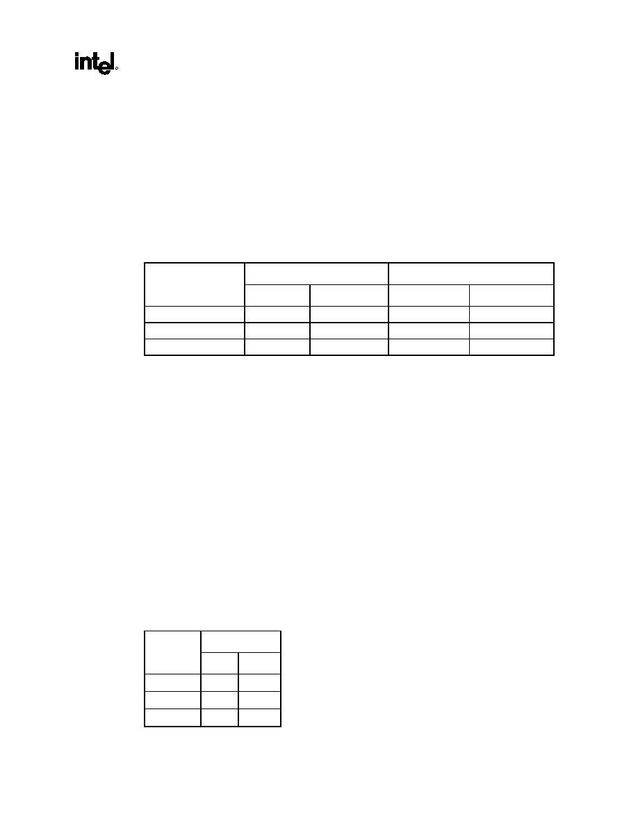
Table 1. Maximum Memory Vs DRAM Densities
Directly Supported
Supported via Repeater(s)
RDRAM
Technology
Increments Maximum Increments
Maximum
64Mb
16 MB
512 MB
16 MB
1 GB
128Mb
32 MB
1 GB
32 MB
2 GB
256Mb
64 MB
2 GB
64 MB
4 GB
The 82840 MCH provides optional ECC error checking for DRAM data integrity. During DRAM writes,
ECC is generated on a QWord (64 bit) basis. Partial QWord writes require a read-modify-write cycle
when ECC is enabled. During DRAM reads, the MCH supports detection of single-bit and multiple-bit
errors, and correct single bit errors, when correction is enabled. The MCH scrubs single bit errors by
writing the corrected value back into DRAM for all reads, when hardware scrubbing is enabled (except
for those launched to satisfy an AGP aperture translation). ECC can only be enabled when all RDRAM
devices populated in a system support the extra two data bits used to store the ECC code.
The 82840 MCH provides a maximum DRAM address decode space of 4 GB. The MCH does not remap
APIC memory space in hardware. It is the BIOS or system designers responsibility to limit DRAM
configuration so that adequate PCI, AGP, High BIOS, and APIC memory space can be allocated.
AGP Interface
A single AGP device or connector (not both) is supported by the MCH AGP interface. The AGP buffers
operate in one of two selectable modes to support the AGP Universal Connector:
∑ 3.3V drive, not 5 volt safe: This mode is compliant to the AGP 1.0 specification
∑ 1.5V drive, not 3.3 volt safe: This mode is compliant with the AGP 2.0 specication
The following table shows the AGP data rate and the signaling levels supported by the MCH.
Signaling Level
Data Rate
1.5V 3.3V
1x AGP *
Yes
Yes
2x AGP
Yes
Yes
4x AGP
Yes
No
* Note AGP FRAME # data rate and signaling level is the same as 1X AGP.

18
Datasheet
The AGP interface supports 4x AGP signaling and 4x Fast Writes. AGP semantic (PIPE# or SBA[7:0])
cycles to DRAM are not snooped on the host bus. AGP FRAME# cycles to DRAM are snooped on the
host bus. The MCH supports PIPE# or SBA[7:0] AGP address mechanisms, but not both simultaneously.
Either the PIPE# or the SBA[7:0] mechanism must be selected during system initialization. High priority
accesses are supported. Only memory writes from either hub interface A or hub interface B to AGP are
allowed. No transactions from AGP to the hub interface are allowed.
MCH Clocking
The MCH has two clock input pins: CPUCLK for the host clock and CLK66 for the AGP clock. Clock
Synthesizer chip(s) are responsible for generating the Host clocks, AGP clocks, PCI clocks, and
Rambus* clocks. These clocks must be synchronous to each other.
The MCH host interface runs at 100 MHz or 133 MHz. The supported speed bins for Direct RDRAM
devices are 300 MHz and 400 MHz. The AGP interface runs at a constant 66 MHz. The hub interface
interfaces run at the same base frequency as the AGP interface.
1.3. Terminology
Term Description
MCH
The 82840 Memory Controller Hub component that contains the processor
interface, DRAM controller, PCI-64 bridge and AGP interface. It
communicates with the 82840 I/O controller hub (ICH) and the 64 bit PCI bus
hub (P64H) over a private interconnect called "hub interface".
ICH
The 82801AA IO Controller Hub component that contains the primary PCI
interface, LPC interface, USB, ATA-66, and other IO functions. The ICH
communicates with the MCH over a private interconnect called hub interface.
P64H
The 82806AA Bus Controller Hub component that contains a 64-bit, 66 MHz
PCI interface.
Host
This term is used synonymously with processor.
Core
The internal base logic in the MCH.
Hub Interface
The private interconnect that ties the MCH to the ICH and/or P64H. In this
document hub interface cycles originating from or destined for the primary PCI
interface on the ICH are generally referred to as hub interface A cycles. Cycles
originating from or destined for any target on the secondary hub interfaces are
described as hub interface B cycles.
Accelerated Graphics
Port (AGP)
The AGP interface in the MCH. The MCH supports a subset of 3.3V, 66 MHz
components, 3.3V 66/133 MHz AGP 2.0 compliant components, and the new
1.5V 66/266 MHz components. PIPE# and SBA addressing cycles and their
associated data phases are generally referred to as AGP transactions.
RSL
Rambus* Signaling Level is the name of the signaling technology used by
Rambus*.

82840
MCH
R
Datasheet
19
Term Description
Single Channel-pair
Mode
In this mode, the 82840 MCH is configured to directly support RDRAM
devices on its dual Rambus* channel. There is no MRH-R used on the memory
subsystem.
Multiple Channel-pair
Mode
In this mode, the 82840 MCH is configured to use MRH-R on the memory
subsystem. Each Rambus* channel of the MRH-R on the MCH Direct Rambus*
Interface A matches with one Rambus* channel of the MRH-R on the Direct
Rambus* Interface B.
Single Device-pair
In the single channel-pair mode, the 82840 MCH is configured to directly
support RDRAM devices on its dual Rambus* channel. Each RDRAM deivce
of the MCH Direct Rambus* Interface A matches with one RDRAM device of
the Direct Rambus* Interface B. There is no MRH-R used on the memory
subsystem.
Multiple Device-pair
In the multiple channel-pair mode, the 82840 MCH is configured to use
MRH-R on the memory subsystem. Each RDRAM deivce on Direct Rambus*
Interface A matches with one RDRAM device on the Direct Rambus* Interface
B.

20
Datasheet
This page is left intentionally blank.

82840
MCH
R
Datasheet
21
2. Signal
Description
This section provides a detailed description of MCH signals. The signals are arranged in functional
groups according to their associated interface.
The "#" symbol at the end of a signal name indicates that the active, or asserted state occurs when the
signal is at a low voltage level. When "#" is not present after the signal name the signal is asserted when
at the high voltage level.
The following notations are used to describe the signal type:
I
Input pin
O Output
pin
I/O
Bi-directional Input/Output pin
s/t/s
Sustained Tristate. This pin is driven to its inactive state prior to tri-stating.
as/t/s
Active Sustained Tristate. This applies to some of the hub interface signals. This pin is weakly
driven to its last driven value.
The signal description also includes the type of buffer used for the particular signal:
GTL+
Open Drain GTL+ interface signal. Refer to the GTL+ I/O Specification for complete details.
AGP
AGP interface signals. These signals can be programmed to be compatible with AGP 2.0 3.3v
or 1.5v Signaling Environment DC and AC Specifications. In 3.3v mode the buffers are not 5v
tolerant. In 1.5v mode the buffers are not 3.3v tolerant.
CMOS CMOS buffers.
RSL
Rambus* Signaling Level interface signal.

22
Datasheet
2.1.
Host Interface Signals
Name Type
Description
ADS# I/O
GTL+
Address Strobe: The PROCESSOR bus owner asserts ADS# to indicate the first of
two cycles of a request phase.
AP[1:0]#
I/O
GTL+
Address Parity: AP[1:0]# provide parity over the address signals. AP1# covers
HA[35:24]#; AP0# covers HA[23:3]#. These signals must be valid for two clocks
beginning when ADS# is asserted.
BERR# I/O
GTL+
Bus Error: The BERR# signal is asserted to indicate an unrecoverable error without
a bus protocol violation.
BNR# I/O
GTL+
Block Next Request: Used to block the current request bus owner from issuing a
new requests. This signal is used to dynamically control the PROCESSOR bus
pipeline depth.
BREQ0# O
GTL+
Symmetric Agent Bus Request: Asserted by the MCH when CPURST# is asserted
to configure the symmetric bus agents. The BREQ0# is negated 2 host clocks after
CPURST# is negated.
BPRI# O
GTL+
Priority Agent Bus Request: The MCH is the only Priority Agent on the
PROCESSOR bus. It asserts this signal to obtain the ownership of the address bus.
This signal has priority over symmetric bus requests and causes the current
symmetric owner to stop issuing new transactions unless the HLOCK# signal was
asserted.
CPURST# O
GTL+
CPU Reset. The CPURST# pin is an output from the MCH. The MCH asserts
CPURST# while RSTIN# (PCIRST# from ICH) is asserted for approximately 1 ms
after RSTIN# is deasserted. The CPURST# allows the processors to begin execution
in a known state.
DBSY# I/O
GTL+
Data Bus Busy: Used by the data bus owner to hold the data bus for transfers
requiring more than one cycle.
DEFER# O
GTL+
Defer: MCH generates a deferred response as defined by the rules of the MCH's
dynamic defer policy. The MCH also uses the DEFER# signal to indicate a processor
retry response.
DEP[7:0]# I/O
GTL+
Host ECC: The DEP[7:0]# signals are driven during the Data Phase by the agent
responsible for driving HD[63:0]#. The DEP[7:0]# signals provide ECC protection for
the signals on the data bus.
DRDY# I/O
GTL+
Data Ready: Asserted for each cycle that data is transferred.
HA[35:3]# I/O
GTL+
Host Address Bus: HA[35:3]# connect to the processor address bus. During
processor cycles, HA[35:3]# are inputs. The MCH drives HA[35:3]# during snoop
cycles on behalf of hub interface and AGP FRAME# initiators. Note that the address
is inverted on the processor bus.
HD[63:0]# I/O
GTL+
Host Data: These signals are connected to the processor data bus. Note that the
data signals are inverted on the processor bus.
HIT# I/O
GTL+
Hit: Indicates that a caching agent is retaining an unmodified version of the
requested line. HIT# is also driven in conjunction with HITM# by the target to extend
the snoop window.
HITM# I/O
GTL+
Hit Modified: Indicates that a caching agent holds a modified version of the
requested line and that this agent assumes responsibility for providing the line. Also,
driven in conjunction with HIT# to extend the snoop window.

82840
MCH
R
Datasheet
23
Name Type
Description
HLOCK# I
GTL+
Host Lock: All processor bus cycles sampled with the assertion of HLOCK# and
ADS#, until the negation of HLOCK# must be atomic (i.e., no hub interface or AGP
snoopable access to DRAM is allowed when HLOCK# is asserted by the processor).
HREQ[4:0]# I/O
GTL+
Host Request Command: Asserted during both clocks of request phase. In the first
clock, HREQ[4:0]# define the transaction type to a level of detail that is sufficient to
begin a snoop request. In the second clock, the signals carry additional information to
define the complete transaction type. The transactions supported by the MCH Host
Bridge are defined in the Functional Description Chapter.
HTRDY# O
GTL+
Host Target Ready: HTRDY# indicates that the target of the processor transaction is
able to enter the data transfer phase.
IERR# I
CMOS
Internal Error: A processor asserts IERR# when it detects an internal error unrelated
to bus operation.
RP# I/O
GTL+
Request Parity: RP# Provides parity protection over ADS# and HREQ[4:0]#. RP#
must be valid for two clocks beginning when ADS# is asserted.
RS[2:0]# O
GTL+
Response Signals: Indicates type of response according to the following the table:
RS[2:0] Response
type
000
Idle state
001
Retry response
010
Deferred response
011
Reserved (not driven by MCH)
100
Hard Failure (not driven by MCH)
101
No data response
110
Implicit Writeback
111
Normal data response
RSP# O
GTL+
Response Parity: RSP# is always driven by the 82840 MCH and must be valid on all
clocks. Response parity is correct if there are an even number of low signals in the
set consisting of the RS[2:0]# signals and the RSP# signal.
The following is the list of processor bus interface signals that are NOT supported by MCH.
Signal
Function
Not Support By MCH
AERR#
Address Parity Error
Error Phase response to parity error
BINIT#
Bus Initialization Signal
Rest of the host bus state machines without full MCH reset

24
Datasheet
2.2.
Direct Rambus* Interface A
Signal Type
Description
CHA_DQA[8:0] I/O
RSL
Rambus Data Byte A (CHA): Bi-directional 9-bit data bus A on the Rambus*
interface A. Data signals used for read and write operations on Rambus* channel
"A".
CHA_DQB[8:0] I/O
RSL
Rambus Data Byte B (CHA): Bi-directional 9-bit data bus B on the Rambus*
interface A. Data signals used for read and write operations on Rambus* channel
"A".
CHA_RQ[7:5]/
CHA_ROW[2:0]
O
RSL
Row Access Control (CHA): Three request package pins containing control and
address information for row accesses. Note that RQ_A[7:5] can also be named as
ROW_A[2:0] signals.
CHA_RQ[4:0]/
CHA_COL[4:0]
O
RSL
Column Access Control (CHA): Five request package pins containing control
and address information for column accesses. Note that RQ_A[4:0] can also be
named as COL_A[4:0] signals.
CHA_CTM I
RSL
Clock To Master (CHA): One of the two differential transmit clock signals used
for RDRAM operations on Rambus* channel "A". It is an input to the MCH and is
generated from an external clock synthesizer.
CHA_CTM# I
RSL
Clock To Master Compliment (CHA): One of the two differential transmit clock
signals used for RDRAM operations on Rambus* channel "A". It is an input to the
MCH and is generated from an external clock synthesizer.
CHA_CFM O
RSL
Clock From Master (CHA): One of the two differential receive clock signals used
for RDRAM operations on Rambus* channel "A". It is an output from the MCH.
CHA_CFM# O
RSL
Clock From Master Compliment(CHA): One of the two differential receive clock
signals used for RDRAM operations on Rambus* channel "A". It is an output from
the MCH.
CHA_EXP[1:0] O
RSL
Expansion (CHA): These signals are used to communicate to an external
Rambus* repeater on Rambus* channel "A". The repeater increases the
maximum memory size supported by the MCH.
CHA_CMD O
CMOS
Command (CHA): Command output to the Rambus* devices used for power
mode control, configuring the SIO daisy chain, and framing SIO operations.
CHA_SCK O
CMOS
Serial Clock (CHA): This signal provides clocking for register accesses and
selects Rambus* channel "A" devices for power management.
CHA_SIO I/O
CMOS
Serial Input/Output (A): Bi-directional serial data signal used for device
initialization, register operations, power mode control, and device reset.

82840
MCH
R
Datasheet
25
2.3.
Direct Rambus* Interface B
Signal Name
Type
Description
CHB_DQA[8:0] I/O
RSL
Rambus Data Byte A (CHB): Bi-directional 9-bit data bus A on the Rambus*
interface B. Data signals used for read and write operations on Rambus* channel
"A".
CHB_DQB[8:0] I/O
RSL
Rambus Data Byte B (CHB): Bi-directional 9-bit data bus B on the Rambus*
interface B. Data signals used for read and write operations on Rambus* channel
"A".
CHB_RQ[7:50]/
CHB_ROW[2:0]
O
RSL
Row Access ControlRequest Control (CHB): Three request package pins
containing control and address information for row accesses. Note that
CHB_RQ[7:5] can also be named as CHB_ROW[2:0] signals.
CHB_RQ[4:0]/
CHB_COL[4:0]
O
RSL
Column Access Control (CHB): Five request package pins containing control
and address information for column accesses. Note that CHB_RQ[4:0] can also
be named as CHB_COL[4:0] signals.
CHB_CTM I
RSL
Clock To Master (CHB): One of the two differential transmit clock signals used
for RDRAM operations on Rambus* channel "B". CHB_CTM is an input to the
MCH and is generated from an external clock synthesizer.
CHB_CTM# I
RSL
Clock To Master Compliment (CHB): One of the two differential transmit clock
signals used for RDRAM operations on Rambus* channel "B". CHB_CTM# is an
input to the MCH and is generated from an external clock synthesizer.
CHB_CFM O
RSL
Clock From Master (CHB): One of the two differential receive clock signals used
for RDRAM operations on Rambus* channel "B". CHB_CFM is an output from the
MCH.
CHB_CFM# O
RSL
Clock From Master Compliment (CHB): One of the two differential receive clock
signals used for RDRAM operations on Rambus* channel "B". CHB_CFM# is an
output from the MCH.
CHB_EXP[1:0] O
RSL
Expansion (CHB): These signals are used to communicate to an external
Rambus* repeater on Rambus* channel "B". The repeater increases the
maximum memory size supported by the MCH.
CHB_CMD O
CMOS
Command (CHB): Command output to the Rambus* devices used for power
mode control, configuring the SIO daisy chain, and framing SIO operations.
CHB_SCK O
CMOS
Serial Clock (CHB): This signal provides clocking for register accesses and
selects Rambus* channel "B" devices for power management.
CHB_SIO I/O
CMOS
Serial Input/Output (CHB): Serial Input/Output A: Bi-directional serial data
signal used for device initialization, register operations, power mode control, and
device reset.

26
Datasheet
2.4.
Hub Interface A Signals
Name Type
Description
HLA_STB I/O
CMOS
Hub interface A Strobe. One of two differential strobe signals used to transmit or
receive packet data over hub interface A.
HLA_STB# I/O
CMOS
Hub interface A Strobe Compliment. One of two differential strobe signals used
to transmit or receive packet data over hub interface A.
HLA[11:0] I/O
CMOS
Hub interface A Signals: Signals used for the hub interface.
HLAZCOMP I/O
CMOS
Impedance Compensation for hub interface A: This signal is used to calibrate
the hub interface A I/O buffers. This signal pin must be connected to a PCB trace
representative of the hub interface A data signal traces but sufficiently long to
present a long shelf before signal reflection occurs. The hub interface A buffers
are calibrated based on the measured shelf voltage.
2.5.
Hub interface B Signals
Name Type
Description
HLB_STB[1:0] I/O
CMOS
Hub interface B Strobe: One of two differential strobe signals used to transmit
or receive packet data over hub interface B.
HLB_STB[1:0]# I/O
CMOS
Hub interface B Strobe Compliment: One of two differential strobe signals
used to transmit or receive packet data over hub interface B.
HLB[19:0] I/O
CMOS
Hub interface B Signals: Signals used for the hub interface.
HLBRCOMP I/O
CMOS
Resistor Compensation for hub interface B: HLBRCOMP is used to calibrate
the hub interface B I/O buffers. This signal pin must be connected to an external
resistor to ground with the value Z0/2. Z0 is the PCB trace impedance used on
the hub interface B.
2.6.
AGP Interface Signals
For more details on the operation of these signals, refer to the AGP Interface Specification, Revision 2.0.
2.6.1.
AGP Addressing Signals
There are two mechanisms the AGP master can use to enqueue AGP requests: PIPE# and SBA (side-
band addressing). Upon initialization, one of the methods is chosen. The master may not switch methods
without a full reset of the system. When
PIPE#
is used to enqueue addresses, the master is not allowed to
queue addresses using the SBA bus. For example, during configuration time, if the master indicates that
it can use either mechanism, the configuration software will indicate which mechanism the master will
use. Once this choice has been made, the master continues to use the mechanism selected until the system
is reset (and reprogrammed) to use the other mode. This change of modes is not a dynamic mechanism
but rather a static decision when the device is first being configured after reset.

82840
MCH
R
Datasheet
27
Name Type
Description
PIPE#
I
AGP
Pipeline:
PIPE# Operation: This signal is asserted by the AGP master to indicate a full-width
adress is to be enqueued on by the target using the AD bus. One address is placed in
the AGP request queue on each rising clock edge while PIPE# is asserted.
SBA Operation: This signal is not used if SBA (Side Band Addressing) is selected.
FRAME# Operation: This signal is not used during AGP FRAME# operation.
SBA[7:0]
I
AGP
Side-band Addressing:
PIPE# Operation: These signals are not used during PIPE# operation.
SBA Operation: These signals (the SBA, or side-band addressing, bus) are used by
the AGP master (graphics component) to place addresses into the AGP request
queue. The SBA bus and AD bus operate independently. That is, transaction can
proceed on the SBA bus and the AD bus simultaneously.
FRAME# Operation: These signals are not used during AGP FRAME# operation.
2.6.2.
AGP Flow Control Signals
Name Type
Description
RBF# I
AGP
Receive Buffer Full:
PIPE# and SBA Operation: Read buffer full indicates if the master is ready to accept
previously requested low priority read data. When RBF# is asserted, the MCH is not
allowed to initiate the return low priority read data. Thus, the MCH can finish returning
the data for the request currently being serviced; however, it can not begin returning
data for the next request. RBF# is only sampled at the beginning of a cycle.
If the AGP master is always ready to accept return read data, it is not required to
implement this signal.
FRAME# Operation: This signal is not used during AGP FRAME# operation.
WBF# I
AGP
Write-Buffer Full:
PIPE# and SBA Operation: Write bufffer full indicates if the master is ready to accept
Fast Write data from the MCH. When WBF# is asserted, the MCH is not allowed to
drive Fast Write data to the AGP master. WBF# is only sampled at the beginning of a
cycle.
If the AGP master is always ready to accept fast write data, it is not required to
implement this signal.
FRAME# Operation: This signal is not used during AGP FRAME# operation.

28
Datasheet
2.6.3.
AGP Status Signals
Name Type
Description
ST[2:0] O
AGP
Status Bus:
PIPE# and SBA Operation: These signals provide information from the arbiter to a AGP
Master on what it may do. ST[2:0] only have meaning to the master when its GNT# is
asserted. When GNT# is deasserted, these signals have no meaning and must be
ignored. Refer to the AGP Interface Specificaiton, revision 2.0 for further explanation of the
ST[2:0] values and their meanings.
FRAME# Operation: These signals are not used during FRAME# based operation; except
that a `111' indicates that the master may begin a FRAME# transaction.
An external 8.2 K
pullup to Vddq is required on each ST[2:0] signal, except ST0. An
external 1 K
pulldown is needed on ST0 for enabling Host Bus ECC generation.
2.6.4.
AGP Clocking Signals--Strobes
Name Type
Description
AD_STB0 I/O
s/t/s
AGP
AD Bus Strobe-0:
1X Operation: This signal is not used during 1X operation.
2X Operation: During 2X operation, this signal provides timing for the AD[15:0] and
C/BE[1:0]# signals. The agent that is providing the data will drive this signal.
4X Operation: During 4X operation, this is one-half of a differential strobe pair that
provides timing information for the AD[15:0] and C/BE[1:0]# signals.
AD_STB0# I/O
s/t/s
AGP
AD Bus Strobe-0 Compliment:
1X Operation: This signal is not used during 1X operation.
2X Operation: During 2X operation, this signal is not used.
4X Operation: During 4X operation, this is one-half of a differential strobe pair that
provides timing information for the AD[15:0] and C/BE[1:0]# signals. The agent that is
providing the data will drive this signal.
AD_STB1 I/O
s/t/s
AGP
AD Bus Strobe-1:
1X Operation: This signal is not used during 1X operation.
2X Operation: During 2X operation, this signal provides timing for the AD[31:16] and
C/BE[3:2]# signals. The agent that is providing the data will drive this signal.
4X Operation: During 4X operation, this is one-half of a differential strobe pair that
provides timing information for the AD[31:16] and C/BE[3:2]# signals. The agent that
is providing the data will drive this signal.
AD_STB1# I/O
s/t/s
AGP
AD Bus Strobe-1 Compliment:
1X Operation: This signal is not used during 1X operation.
2X Operation: During 2X operation, this signal is not used.
4X Operation: During 4X operation, this is one-half of a differential strobe pair that
provides timing information for the AD[16:31] and C/BE[2:3]# signals. The agent that
is providing the data will drive this signal.

82840
MCH
R
Datasheet
29
Name Type
Description
SB_STB I
AGP
SBA Bus Strobe:
1X Operation: This signal is not used during 1X operation.
2X Operation: During 2X operation, this signal provides timing for the SBA bus
signals. The agent that is driving the SBA bus will drive this signal.
4X Operation: During 4X operation, this is one-half of a differential strobe pair that
provides timing information for the SBA bus signals. The agent that is driving the
SBA bus will drive this signal.
SB_STB# I
AGP
SBA Bus Strobe Compliment:
1X Operation: This signal is not used during 1X operation.
2X Operation: During 2X operation, this signal is not used.
4X Operation: During 4X operation, this is one-half of a differential strobe pair that
provides timing information for the SBA bus signals. The agent that is driving the
SBA bus will drive this signal.
2.6.5.
AGP FRAME# Signals
For transactions on the AGP interface carried using AGP FRAME# protocol, these signals operate
similar to their semantics in the PCI 2.1 specification. The exact role of all AGP FRAME# signals are
defined below.
Name Type
Description
G_FRAME# I/O
s/t/s
AGP
FRAME:
PIPE# and SBA Operation: Not used by AGP SBA and PIPE#, but used during AGP
FRAME# .
Fast Write Operation: G_FRAME# is used to frame transactions as an output from
the MCH during Fast Writes.
FRAME# Operation: G_FRAME# is an output when the MCH acts as an initiator on
the AGP Interface. G_FRAME# is asserted by the MCH to indicate the beginning and
duration of an access. G_FRAME# is an input when the MCH acts as a FRAME#
based AGP target. As a FRAME# based AGP target, the MCH latches the
C/BE[3:0]# and the AD[31:0] signals on the first clock edge on which it samples
FRAME# active.
G_IRDY# I/O
s/t/s
AGP
Initiator Ready:
PIPE# and SBA Operation: Not used while enqueueing requests via AGP SBA and
PIPE#, but used during the data phase of PIPE# and SBA transactions.
FRAME# Operation: G_IRDY# is an output when MCH acts as a FRAME# based
AGP initiator and an input when the MCH acts as a FRAME# based AGP target. The
assertion of G_IRDY# indicates the current FRAME# based AGP bus initiator's ability
to complete the current data phase of the transaction.
Fast Write Operation: G_IRDY# indicates the AGP compliant master is ready to
provide all write data for the current transaction. Once G_IRDY# is asserted for a
write operation, the master is not allowed to insert wait states. The master is never
allowed to insert a wait state during the initial data transfer (32 bytes) of a write
transaction. However, it may insert wait states after each 32 byte block is transferred.

30
Datasheet
Name Type
Description
G_TRDY# I/O
s/t/s
AGP
Target Ready:
PIPE# and SBA Operation: Not used while enqueueing requests via AGP SBA and
PIPE#, but used during the data phase of PIPE# and SBA transactions.
FRAME# Operation: G_TRDY# is an input when the MCH acts as an AGP initiator
and an output when the MCH acts as a FRAME# based AGP target. The assertion of
G_TRDY# indicates the target's ability to complete the current data phase of the
transaction.
Fast Write Operation: G_TRDY# indicates the AGP compliant target is ready to
receive write data for the entire transaction (when the transfer size is less than or
equal to 32 bytes) or is ready to transfer the initial or subsequent block (32 bytes) of
data when the transfer size is greater than 32 bytes. The target is allowed to insert
wait states after each block (32 bytes) is transferred on write transactions.
G_STOP# I/O
s/t/s
AGP
Stop:
PIPE# and SBA Operation: This signal is not used during PIPE# or SBA operation.
FRAME# Operation: STOP# is an input when the MCH acts as a FRAME# based
AGP initiator and an output when the MCH acts as a FRAME# based AGP target.
STOP# is used for disconnect, retry, and abort sequences on the AGP interface.
G_DEVSEL# I/O
s/t/s
AGP
Device Select:
PIPE# and SBA Operation: This signal is not used during PIPE# or SBA operation.
FRAME# Operation: DEVSEL#, when asserted, indicates that a FRAME# based
AGP target device has decoded its address as the target of the current access. The
MCH asserts DEVSEL# based on the DRAM address range being accessed by a PCI
initiator. As an input it indicates whether any device on the bus has been selected.
Fast Write Operation: G_DEVSEL# is used when the transaction cannot complete
during the block data transfer
G_REQ# I
AGP
Request:
SBA Operation: This signal is not used during PIPE# or SBA operation.
PIPE# and FRAME# Operation: REQ#, when asserted, indicates that a FRAME# or
PIPE# based AGP master is requesting use of the AGP interface. This signal is an
input into the MCH.
G_GNT# O
AGP
Grant:
SBA, PIPE# and FRAME# Operation: GNT# along with the information on the
ST[2:0] signals (status bus) indicates how the AGP interface will be used next. Refer
to the AGP Interface Specificaiton, revision 2.0 for further explanation of the ST[2:0]
values and their meanings.
G_AD[31:0] I/O
AGP
Address/Data Bus:
PIPE# and FRAME# Operation: AD[31:0] are used to transfer both address and
data information on the AGP inteface.
SBA Operation: AD[31:0] are used to transfer data on the AGP interface.

82840
MCH
R
Datasheet
31
Name Type
Description
G_C/BE[3:0]# I/O
AGP
Command/Byte Enable:
FRAME# Operation: During the address phase of a transaction, C/BE[3:0]# define
the bus command. During the data phase, C/BE[3:0]# are used as byte enables. The
byte enables determine which byte lanes carry meaningful data. The commands
issued on the C/BEx# signals during FRAME# based AGP are the same C/BEx#
command described in the PCI 2.1 specification.
PIPE# Operation: When an address is enqueued using PIPE#, the C/BEx# signals
carry command information. Refer to the AGP 2.0 Interface Specification Revision
2.0 for the definition of these commands. The command encoding used during PIPE#
based AGP is Different than the command encoding used during FRAME# based
AGP cycles (or standard PCI cycles on a PCI bus).
SBA Operation: These signals are not used during SBA operation.
G_PAR I/O
AGP
Parity:
FRAME# Operation: G_PAR is driven by the MCH when it acts as a FRAME# based
AGP initiator during address and data phases for a write cycle, and during the
address phase for a read cycle. PAR is driven by the MCH when it acts as a
FRAME# based AGP target during each data phase of a FRAME# based AGP
memory read cycle. Even parity is generated across AD[31:0] and C/BE[3:0]#.
SBA and PIPE# Operation: This signal is not used during SBA and PIPE#
operation.
G_SERR# I
AGP
System Error: G_SERR# can be pulsed to report a system error condition. Upon
sampling G_SERR# active, the MCH can generate a hub interface SERR cycle to the
ICH.
NOTES:
1. PCIRST# from the ICH is connected to RSTIN# and is used to reset AGP interface logic within the MCH. The
AGP agent will also use PCIRST# provided by the ICH as an input to reset its internal logic.
2. The LOCK# Signal is NOT supported on the AGP interface, even for FRAME based AGP operations.
3. The PERR# Signal is NOT supported on the AGP interface.
2.7.
Clocks, Reset, and Miscellaneous
Name Type
Description
CPUCLK I
CMOS
Host Clock In: CPUCLK receives a buffered host clock from the external clock
synthesizer. This clock is used by all of the MCH logic that is in the Host clock
domain.
Note that the clock synthesizer drives this signal to 2.5V.
CLK66 I
CMOS
66MHz Clock In:. CLK66 receives a buffered clock from the clock synthesizer
that is synchronously derived from the host clock. This clock is used by all of the
MCH logic that is in the AGP clock domain.
Note that the clock synthesizer drives this signal to 3.3V, and this input is 3.3V
tolerant.
RCLKOUT[A,B] O
CMOS
Rambus Clock Out: RCLKOUT[A,B] provide divided down versions of the
Rambus* clock as feedback to the Rambus* clock synthesizers for phase
alignment.
Note that this pin will only be driven to 1.8V.
HCLKOUT[A,B] O
CMOS
Host Clock Out: HCLKOUT[A,B] provide divided down versions of the host clock
as feedback to the Rambus* clock synthesizers for phase alignment.
Note that this pin will only be driven to 1.8V.

32
Datasheet
Name Type
Description
RSTIN# I
CMOS
Reset In: When asserted, RSTIN# asynchronously resets the MCH logic. This
signal is connected to the PCIRST# output of the ICH. All AGP output and bi-
directional signals will also tri-state compliant to PCI Rev 2.0 and 2.1
specifications.
Note that this input needs to be 3.3V tolerant.
TEST# I
CMOS
Test Input: This pin is used for manufacturing and board level test purposes.
OVERT# I
CMOS
Overtemperature condition: An active low input signal generated by external
hardware to indicated the overtemperature condition in the memory subsystem.
2.8.
Voltage References, PLL Power
Signal Name
Description
GTLREF[A:B]
GTL Reference: Reference voltage input for the Host GTL interface.
AGPRCOMP
AGP RCOMP: AGPRCOMP is used to calibrate AGP GTL I/O buffers. This signal must be
connected to a PCB trace representative of the AGP bus data signal traces but sufficiently
long to present a long shelf before signal reflection occurs. The AGP buffers are calibrated
based on the measured shelf voltage.
CHA_REF[1:0]
Rambus Channel A Reference: Reference voltage input for the Rambus* Channel A RSL
interface.
CHB_REF[1:0]
Rambus Channel B Reference: Reference voltage input for the Rambus* Channel B RSL
interface.
AGPREF
AGP Reference: Reference voltage input for the AGP interface.
HLAREF
hub interface A Reference: Refererence voltage input for the hub interface.
HLBREF
hub interface B Reference: Refererence voltage input for the hub interface.
VCC1_8
1.8V Power Supply: The 1.8v power input pin
VDDQ
AGP I/O Power Supply: The power supply input for the AGP I/O supply.
VTT
AGTL+ 1.5V Volatage: The GTL+ bus 1.5v termination voltage inputs.
VSS
Ground:

82840
MCH
R
Datasheet
33
2.9. Strap
Signals
This section provides the strap options invoked by various MCH signal pins.
Name Definition
HLA10
Host Bus Frequency: This signal is latched on the rising edge of RSTIN#. It indicates what the
host FSB frequency is to select the correct internal frequency ratios. This value can be read from
the MCHCFG register. There is no internal pullup or pulldown resistor.
HLA10
Host Bus Frequency
0
100 MHz
1
133 MHz
HA7#
CPU Bus In-Order Queue Depth: The value on HA7# is sampled by all host bus agents (including
the MCH) on the rising edge of CPURST#. It's latched value determines the maximum IOQ depth
mode supported on the host bus. If HA7# is sampled low the IOQ depth on the bus is one. If HA7#
is sampled high, the IOQ depth on the bus is the maximum of eight. When the IOQ depth on the
bus is set to 8, the MCH does not limit the number of queued transactions, since it supports an
IOQ depth of 8.
The MCH does not drive HA7# during CPURST#. If an IOQ depth of 1 is desired, HA7# needs to
be driven low during CPURST# by external logic.
ST0
Host Bus ECC Generation: ST0 is latched on the rising edge of RSTIN#. It is used to enable the
data ECC protection covering HD[63:0]#. This value can be read from the HERRCTL register.
There is no internal pullup or pulldown resistor.
To strap for Host Bus ECC enabled, a 1 K
pulldown should be connected to ST0. ST0 should
have a 8.2 K
external pullup resistor to Vddq to disable the Hot Bus ECC generation.
ST0
ECC Generation on DEP[7:0]#
0
Enable (external 1 K
pulldown)
1
Disable (external 8.2 K
pullup))

34
Datasheet
This page is left intentionally blank.

82840
MCH
R
Datasheet
35
3. Register
Description
This chapter describes the MCH PCI configuration registers. A detailed bit description is provided. The
MCH contains two sets of software accessible registers, accessed via the Host I/O address space:
∑ Control registers I/O mapped into the host I/O space, which control access to PCI and AGP
configuration space (see section entitled I/O Mapped Registers)
∑ Internal configuration registers residing within the MCH are partitioned into two logical device
register sets ("logical" since they reside within a single physical device). The first register set is
dedicated to Host-Hub interface Bridge/DRAM Controller functionality (controls PCI_A i.e.
DRAM configuration, other chip-set operating parameters and optional features). The second
register block is dedicated to Host-AGP Bridge functions (controls AGP interface configurations
and operating parameters).
The MCH supports PCI configuration space accesses using the mechanism denoted as Configuration
Mechanism #1 in the PCI specification.
The MCH internal registers (both I/O Mapped and Configuration registers) are accessible by the host.
The registers can be accessed as Byte, Word (16-bit), or DWord (32-bit) quantities, with the exception of
CONF_ADDR which can only be accessed as a Dword. All multi-byte numeric fields use "little-endian"
ordering (i.e., lower addresses contain the least significant parts of the field).
3.1.
Register Nomenclature and Access Attributes
Symbol Description
RO
Read Only. If a register is read only, writes to this register have no effect.
R/W
Read/Write. A register with this attribute can be read and written
R/W/L
Read/Write/Lock. A register with this attribute can be read, written, and Lock.
R/WC
Read/Write Clear. A register bit with this attribute can be read and written. However, a
write of a 1 clears (sets to 0) the corresponding bit and a write of a 0 has no effect.
R/WO
Read/Write Once. A register bit with this attribute can be written to only once after
power up. After the first write, the bit becomes read only.
L
Lock. A register bit with this attribute becomes Read Only after a lock bit is set.
Reserved
Bits
Software must deal correctly with fields that are reserved. On reads, software must use
appropriate masks to extract the defined bits and not rely on reserved bits being any
particular value. On writes, software must ensure that the values of reserved bit positions
are preserved. That is, the values of reserved bit positions must first be read, merged
with the new values for other bit positions and then written back. Note that software does
not need to perform read, merge, write operation for the configuration address register.

36
Datasheet
Symbol Description
Reserved
Registers
In addition to reserved bits within a register, the MCH contains address locations in the
configuration space of the Host-hub interface A Bridge/DRAM Controller, Host-AGP
Bridge and Host-Hub interface B Bridge entities that are marked "Reserved". When a
"Reserved" register location is read, a random value can be returned. ("Reserved"
registers can be 8-, 16-, or 32-bit in size). Registers that are marked "Reserved" must
not be modified by system software. Writes to "Reserved" registers may cause system
failure.
Default
Value
Upon
Reset
Upon a Full Reset, the MCH sets all of its internal configuration registers to
predetermined default states. Upon a Partial Reset some of the MCH configuration
register bits associated with DRAM configuration are not reset. These register bits are
identified in the bit descriptions below. Some register values at reset are determined by
external strapping options. The default state represents the minimum functionality
feature set required to successfully bring up the system. Hence, it does not represent the
optimal system configuration. It is the responsibility of the system initialization software
(usually BIOS) to properly determine the DRAM configurations, operating parameters
and optional system features that are applicable, and to program the MCH registers
accordingly.
3.2.
PCI Configuration Space Access
The MCH and the ICH are physically connected by hub interface A. From a configuration standpoint,
hub interface A is logically PCI bus #0. As a result, all devices internal to the MCH and ICH appear to
be on PCI bus #0. The system's primary PCI expansion bus is physically attached to the ICH and, from a
configuration perspective, appears to be a hierarchical PCI bus behind a PCI-to-PCI bridge and,
therefore, has a programmable PCI Bus number.
Note: The primary PCI bus is referred to as PCI_A in this document and is not PCI bus #0 from a configuration
standpoint. The secondary hub interface port appears to system software to be a real PCI bus behind a
PCI-to-PCI bridge resident as device 2 on PCI bus #0.
The MCH contains three PCI devices within a single physical component. The configuration registers for
devices 0, 1, and 2 are mapped as devices residing on PCI bus #0.
∑ Device 0: Host-hub interface A Bridge/DRAM Controller. Logically this appears as a PCI
device residing on PCI bus #0. Physically Device 0 contains the standard PCI registers, DRAM
registers, the Graphics Aperture controller, and other MCH specific registers.
∑ Device 1: Host-AGP Bridge. Logically this appears as a "virtual" PCI-to-PCI bridge residing on
PCI bus #0. Physically Device 1 contains the standard PCI-to-PCI bridge registers and the standard
AGP configuration registers (including the AGP I/O and memory address mapping).
∑ Device 2 Host-hub interface B Bridge. Logically this bridge appears to be a PCI-to-PCI bridge
device residing on PCI bus #0. Physically, device 2 contains the standard PCI-to-PCI registers.
Note: A physical PCI bus #0 does not exist. The hub interface and the internal devices in the MCH and ICH
logically constitute PCI Bus #0 to configuration software.

82840
MCH
R
Datasheet
37
PCI Bus Configuration Mechanism
The PCI Bus defines a slot based "configuration space" that allows each device to contain up to 8
functions, with each function containing up to 256 8-bit configuration registers. The PCI specification
defines two bus cycles to access the PCI configuration space: Configuration Read and Configuration
Write. Memory and I/O spaces are supported directly by the processor. Configuration space is supported
by a mapping mechanism implemented within the MCH. The PCI specification defines two mechanisms
to access configuration space, Mechanism #1 and Mechanism #2. The MCH supports only
Mechanism #1.
The configuration access mechanism makes use of the CONF_ADDR Register and CONF_DATA
Register. To reference a configuration register a DWord I/O write cycle is used to place a value into
CONF_ADDR that specifies:
∑ The PCI bus
∑ The device on that bus
∑ The function within the device
∑ A specific configuration register of the device function being accessed.
CONF_ADDR[31] must be 1 to enable a configuration cycle. CONF_DATA then becomes a window
into the four bytes of configuration space specified by the contents of CONF_ADDR. Any read or write
to CONF_DATA will result in the MCH translating the CONF_ADDR into the appropriate configuration
cycle.
The MCH is responsible for translating and routing the processor I/O accesses to the CONF_ADDR and
CONF_DATA registers to internal MCH configuration registers, the hub interfaces or AGP.
Routing Configuration Accesses to Primary PCI (PCI_A), or AGP
The MCH supports three bus interfaces: hub interface A, hub interface B, and AGP. PCI configuration
cycles are selectively routed to one of these interfaces. The MCH is responsible for routing PCI
configuration cycles to the proper interface. PCI configuration cycles to ICH internal devices and PCI_A
(including downstream devices) are routed to the ICH via the hub interface A. AGP configuration cycles
are routed to AGP. PCI configuration cycles to P64H are routed to hub interface B. The AGP interface is
treated as a separate PCI bus from the configuration point of view. Routing of configuration accesses to
both hub interface B and AGP is controlled via the standard PCI-PCI bridge mechanism using
information contained within the Primary Bus Number, the Secondary Bus Number, and the Subordinate
Bus Number registers of the Host-AGP internal "virtual" PCI-PCI bridge device.

38
Datasheet
Logical PCI Bus #0 Configuration Mechanism
The MCH decodes the Bus Number (bits 23:16) and the Device Number fields of the CONF_ADDR
register. If the Bus Number field of CONF_ADDR is 0 the configuration cycle is targeting a PCI Bus #0
device.
∑ The Host-hub interface A Bridge/DRAM Controller entity within the MCH is hardwired as
Device 0 on PCI Bus #0.
∑ The Host-AGP Bridge entity within the MCH is hardwired as Device 1 on PCI Bus #0.
∑ The Host-hub interface B bridge entity within the MCH is hardwired as Device 2 on PCI Bus #0.
Configuration cycles to the MCH internal devices are confined to the MCH and not sent over the hub
interface. Accesses to devices #3 to #31 will be forwarded over the hub interface A.
Primary PCI (PCI_A) and Downstream Configuration Mechanism
If the Bus Number in the CONF_ADDR is non-zero, and is less than the value programmed into both of
the MCH's device 1 and device 2 Secondary Bus Number register or greater than the value programmed
into the Subordinate Bus Number Register, the MCH will generate a Type 1 configuration cycle over hub
interface A. The ICH compares the non-zero Bus Number with the Secondary Bus Number and
Subordinate Bus Number registers of its P2P bridges to determine if the configuration cycle is meant for
Primary PCI (PCI_A), or a downstream PCI bus.
AGP Bus Configuration Mechanism
From the chipset configuration perspective, AGP is seen as another PCI bus interface residing on a
Secondary Bus side of the "virtual" PCI-PCI bridge referred to as the MCH Host-AGP bridge. On the
Primary bus side, the "virtual" PCI-PCI bridge is attached to PCI Bus #0. Therefore the Primary Bus
Number register is hardwired to "0". The "virtual" PCI-PCI bridge entity converts Type #1 PCI Bus
Configuration cycles on PCI Bus #0 into Type 0 or Type 1 configuration cycles on the AGP interface.
Type 1 configuration cycles on PCI Bus #0 that have a BUS NUMBER that matches the Secondary Bus
Number of the MCH Host-AGP bridge will be translated into Type 0 configuration cycles on the AGP
interface.
if the Bus Number is non-zero, greater than the value programmed into the Secondary Bus Number
register, and less than or equal to the value programmed into the Subordinate Bus Number register, the
MCH will generate a Type 1 PCI configuration cycle on AGP.

82840
MCH
R
Datasheet
39
3.3.
I/O Mapped Registers
The MCH contains a set of registers that reside in the host I/O address space
- the Configuration Address
(CONF_ADDR) Register and the Configuration Data (CONF_DATA) Register. The Configuration
Address Register enables/disables the configuration space and determines what portion of configuration
space is visible through the Configuration Data window.
3.3.1. CONF_ADDR
Configuration Address Register
I/O Address:
0CF8h Accessed as a DWord
Default Value:
00000000h
Access: Read/Write
Size: 32
bits
CONF_ADDR is a 32 bit register accessed only when referenced as a DWord. A Byte or Word reference
will "pass through" the Configuration Address Register and the hub interface onto the PCI0 bus as an I/O
cycle. The CONF_ADDR register contains the Bus Number, Device Number, Function Number, and
Register Number for which a subsequent configuration access is intended.
Bit Descriptions
31
Configuration Enable (CFGE): This bit controls access to PCI space.
1 = Enable.
0 = Disable.
30:24
Reserved (These bits are read only and have a value of 0).
23:16
Bus Number: When the Bus Number is programmed to 00h, the target of the PCI configuration cycle
is a hub interface agent (MCH, ICH, etc.).
The configuration cycle is forwarded to hub interface A if the Bus Number is programmed to 00h and
the MCH is not the target (the device number is
3).
If the Bus Number is non-zero and matches the value programmed into the Secondary Bus Number
Register of Device 1, a Type 0 PCI configuration cycle will be generated on AGP.
If the Bus Number is non-zero, greater than the value in the Secondary Bus Number register of
Device 1, and less than or equal to the value programmed into the Subordinate Bus Number Register
of Device 1, a Type 1 PCI configuration cycle will be generated on AGP.
If the Bus Number is non-zero and matches the value programmed into the Secondary Bus Number
Register of Device 2, a Type 0 PCI configuration cycle will be generated on hub interface B.
If the Bus Number is non-zero, greater than the value in the Secondary Bus Number register of
Device 2, and less than or equal to the value programmed into the Subordinate Bus Number Register
of Device 2, a Type 1 PCI configuration cycle will be generated on hub interface B.
If the Bus Number is non-zero and does not fall within the ranges enumerated by Device 1 and Device
2's Secondary Bus Number or Subordinate Bus Number Register, a hub interface A Configuration
Cycle is generated.

40
Datasheet
Bit Descriptions
15:11
Device Number: This field selects one agent on the PCI bus selected by the Bus Number. When the
Bus Number field is "00", the MCH decodes the Device Number field. The MCH is always Device
Number 0 for the Host-hub interface A bridge entity, Device Number 1 for the Host-AGP entity, and
Device Number 2 for the Host-hub interface B entity. Therefore, when the Bus Number =0 and the
Device Number=0, 1, or 2 the internal MCH devices are selected. Note that AD11, AD12, and AD13
must not be connected to any other PCI_A bus device as IDSEL signals.
If the Bus Number is non-zero and matches the value programmed into the Secondary Bus Number
Register, a Type 0 PCI configuration cycle will be generated on AGP. The MCH decodes the Device
Number field [15:11] and asserts the appropriate GAD signal as an IDSEL. For PCI-to-PCI Bridge
translation, one of 16 IDSELs are generated. When bit [15] = 0, bits [14:11] are decoded to assert a
single AD[31:16] IDSEL. GAD16 is asserted to access Device 0, GAD17 for Device 1, and so forth up
to Device 16 which asserts AD31. All device numbers higher than 16 cause a type 0 configuration
access with no IDSEL asserted, which results in a Master Abort reported in the MCH's "virtual" PCI-
PCI bridge registers.
For Bus Numbers resulting in hub interface A or hub interface B configuration cycles, the MCH
propagates the Device Number field as A[15:11].
10:8
Function Number: This field is mapped to GAD[10:8] during AGP Configuration cycles and A[10:8]
during hub interface A or hub interface B configuration cycles. This allows the configuration registers
of a particular function in a multi-function device to be accessed. The MCH ignores configuration
cycles to it's two internal devices if the function number is not equal to 0.
7:2
Register Number: This field selects one register within a particular Bus, Device, and Function as
specified by the other fields in the Configuration Address Register. This field is mapped to GAD[7:2]
during AGP Configuration cycles and A[7:2] during hub interface A or hub interface B Configuration
cycles.
1:0 Reserved.
3.3.2.
CONF_DATA--Configuration Data Register
I/O Address:
0CFCh
Default Value:
00000000h
Access: Read/Write
Size: 32
bits
CONF_DATA is a 32 bit read/write window into configuration space. The portion of configuration space
that is referenced by CONF_DATA is determined by the contents of CONF_ADDR.
Bit Descriptions
31:0
Configuration Data Window (CDW): If bit 31 of CONF_ADDR is 1, any I/O access to the
CONF_DATA register will be mapped to configuration space using the contents of CONF_ADDR.

82840
MCH
R
Datasheet
41
3.4.
Host-Hub interface A Bridge/DRAM Controller Device
Registers (Device 0)
An "s" in the Default Value field means that the power-up default value for that bit is determined by a
strap.
Table 2. MCH Configuration Space (Device 0)
Address
Offset
Symbol Register
Name Default
Access
00≠01h VID
Vendor
Identification
8086h RO
02≠03h DID
Device
Identification
1A21h RO
04≠05h PCICMD
PCI
Command
0006h R/W
06≠07h PCISTS
PCI
Status
0090h/0080h
RO,
R/WC
08h RID
Revision
Identification
00h RO
0Ah SUBC
Sub-Class
Code
00h RO
0Bh BCC
Base
Class
Code
06h RO
0Dh MLT
Master
Latency
Timer
00h R/W
0Eh HDR
Header
Type
00h R/W
10≠13h
APBASE
Aperture Base Configuration
00000008h
R/W
2C≠2Dh SVID
Subsystem
Vendor
Identification
0000h R/WO
2E≠2Fh SID
Subsystem
Identification
0000h
R/WO
34h
CAPPTR
Capabilities Pointer
A0h / 00h
RO
40≠4Fh
GAR[0:15]
RDRAM Group Architecture Register [15:0]
80h
R/W
50≠51h MCHCFG
MCH
Configuration
00ss00000000
0s00b
R/WO,R/W
52≠57h --
Reserved
-- --
58h
FDHC
Fixed DRAM Hole Control
00h
R/W
59≠5Fh
PAM[0:6]
Programmable Attribute Map [0:6]
00h
R/W
60≠61h
GBA0
RDRAM Group Boundary Address 0
0001h
R/W
62≠63h
GBA1
RDRAM Group Boundary Address 1
0001h
R/W
64≠65h
GBA2
RDRAM Group Boundary Address 2
0001h
R/W
66≠67h
GBA3
RDRAM Group Boundary Address 3
0001h
R/W
68≠69h
GBA4
RDRAM Group Boundary Address 4
0001h
R/W
6A≠6Bh
GBA5
RDRAM Group Boundary Address 5
0001h
R/W
6C-6Dh
GBA6
RDRAM Group Boundary Address 6
0001h
R/W
6E≠6Fh
GBA7
RDRAM Group Boundary Address 7
0001h
R/W
70≠71h
GBA8
RDRAM Group Boundary Address 8
0001h
R/W
72≠73h
GBA9
RDRAM Group Boundary Address 9
0001h
R/W

42
Datasheet
Address
Offset
Symbol Register
Name Default
Access
74≠75h
GBA10
RDRAM Group Boundary Address A
0001h
R/W
76≠77h
GBA11
RDRAM Group Boundary Address B
0001h
R/W
78≠79h
GBA12
RDRAM Group Boundary Address C
0001h
R/W
7A≠7Bh
GBA13
RDRAM Group Boundary Address D
0001h
R/W
7C≠7Dh
GBA14
RDRAM Group Boundary Address E
0001h
R/W
7E≠7Fh
GBA15
RDRAM Group Boundary Address F
0001h
R/W
80≠87h --
Reserved
-- --
88h
RDPS
RDRAM Pool Sizing Register
10h
R/W
89≠8Fh --
Reserved
-- --
90≠93h
DRD
RDRAM Device Register Data
0000h
R/W
94≠97h
94≠96h
RICM or
--
RDRAM Initialization Control Management
Reserved
0000_0000h
--
R/W
--
98≠9Ch --
Reserved
-- --
9Dh
SMRAM
System Management RAM Control
02h
R/W
9Eh
ESMRAMC
Extended System Management RAM Control
38h
R/W
9Fh
--
Reserved
--
--
A0≠A3h ACAPID
AGP
Capability
Identifier
00200002h
/00000000h
RO
A4≠A7h AGPSTAT
AGP
Status
Register
1F000217h RO
A8≠ABh AGPCMD
AGP
Command
Register
00000000h RW
AC≠AFh --
Reserved
-- --
B0≠B3h AGPCTRL
AGP
Control
Register
00000000h R/W
B4h APSIZE
Aperture
Size
00h R/W
B5≠B7h --
Reserved
-- --
B8≠BBh
ATTBASE
Aperture Translation Table
00000000h
R/W
BCh
AMTT
AGP MTT Control Register
00h
R/W
BDh
LPTT
AGP Low Priority Transaction Timer Reg.
00h
R/W
BEh RDT
RDRAM
Timing
00h R/W
BFh
DRAMRC
RDRAM Refresh Control
00h
R/W
C0≠C3h --
Reserved
-- --
C4≠C5h
TOM
Top of Low Memory
0000h
R/W
C6≠C7h --
Reserved
0000h --
C8≠C9h
ERRSTS
Error Status Register
0000h
R/WC
CA≠CBh
ERRCMD
Error Command Register
0000h
R/W
CC≠CDh SMICMD
SMI
Command
Register
0000h
R/W
CE≠CFh SCICMD
SCI
Command
Register
0000h R/W
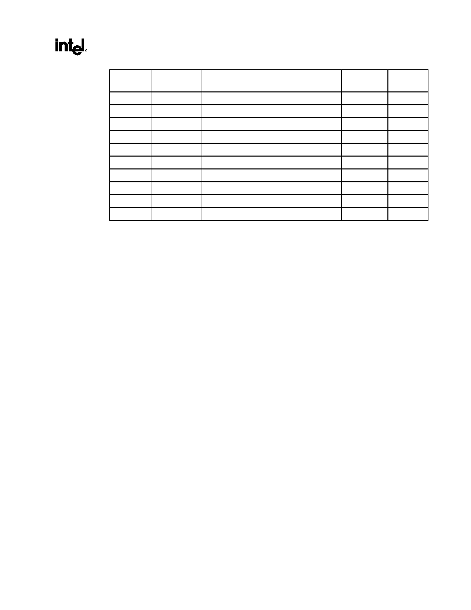
82840
MCH
R
Datasheet
43
Address
Offset
Symbol Register
Name Default
Access
D0≠DDh --
Reserved
-- --
DE≠DFh SKPD
Scratchpad
Data
0000h R/W
E0≠E1h
HERRCTL_STS Host Error Control/Status
0000h
R/W, R/WC
E2≠E3h
DERRCTL_STS DRAM ERROR Control/Status
0000h
R/W,R/WC
E4≠E7h EAP
Error
Address
Pointer
0000h R/W
E8≠EBh
AGPBCTRL
AGP Buffer Strength Control
0000h
R/W
EC≠F5h --
Reserved
-- --
F6
AGPAPPEND
AGP Append Disable
00h
R/W
F7
GTLNCLAMP
GTL N Clamp Disable
00h
R/W
F8≠FFh --
Reserved
-- --

44
Datasheet
3.4.1.
VID--Vendor Identification Register (Device 0)
Address Offset:
00≠01h
Default Value:
8086h
Attribute: Read
Only
Size: 16
bits
The VID Register contains the vendor identification number. This 16-bit register combined with the
Device Identification Register uniquely identify any PCI device. Writes to this register have no effect.
Bit Description
15:0
Vendor Identification Number. This is a 16-bit value assigned to Intel. Intel VID = 8086h.
3.4.2.
DID--Device Identification Register (Device 0)
Address Offset:
02≠03h
Default Value:
1A21h
Attribute: Read
Only
Size: 16
bits
This 16-bit register combined with the Vendor Identification register uniquely identifies any PCI device.
Writes to this register have no effect.
Bit Description
15:0
Device Identification Number. This is a 16 bit value assigned to the MCH Host-hub interface A
Bridge/DRAM Controller Function #0.
DID = 1A21h for the MCH device 0.

82840
MCH
R
Datasheet
45
3.4.3.
PCICMD--PCI Command Register (Device 0)
Address Offset:
04≠05h
Default: 0006h
Access:
Read/Write, Read Only
Size 16
bits
Since MCH Device 0 does not physically reside on PCI0 many of the bits are not implemented. Writes to
Not Implemented bits have no affect.
Bit Descriptions
15:10 Reserved.
9
Fast Back-to-Back--RO: (Not Implemented). Hardwired to 0. This bit controls whether or not the
master can do fast back-to-back writes. Since Device 0 is strictly a target, this bit is not implemented.
8
SERR Enable (SERRE)--R/W: This bit is a global enable bit for Device 0 SERR messaging. The
MCH does not have an SERR# signal. The MCH communicates the SERR# condition by sending a
SERR message to the ICH.
1 = Enable. The MCH is enabled to generate SERR messages over the hub interface for specific
Device 0 error conditions that are individually enabled in the ERRCMD register. The error status is
reported in the ERRSTS and PCISTS registers.
0 = The SERR message is not generated by the MCH for Device 0.
NOTE: This bit only controls SERR message for the Device 0. Devices 1 and 2 have their own
SERRE bits to control error reporting for error conditions occurring on their respective devices.
7
Address/Data Stepping--RO: (Not Implemented). Hardwired to 0. Address/data stepping is not
implemented in the MCH.
6
Parity Error Enable (PERRE)--R/W:
1 = Detection of a parity error by the MCH on the hub interface A results in an SERR message being
sent to the ICH, if the SERRE bit (bit 9 of this register) is also set.
0 = Parity errors detected on hub interface A by the MCH do not result in an SERR message.
5
VGA Palette Snoop--RO: (Not Implemented). Hardwired to 0.
4
Memory Write and Invalidate Enable(MWIE)--RO: (Not Implemented). Hardwired to 0.
3
Special Cycle Enable(SCE)--RO: (Not Implemented). Hardwired to 0.
2
Bus Master Enable (BME) --RO: (Not Implemented). Hardwired to 1. The MCH is always enabled
as a master on hub interface A.
1
Memory Access Enable (MAE) --RO: (Not Implemented). Hardwired to 1. The MCH always allows
access to main memory.
0
I/O Access Enable (IOAE)--RO: (Not Implemented). Hardwired to a 0.

46
Datasheet
3.4.4.
PCISTS--PCI Status Register (Device 0)
Address Offset:
06≠07h
Default Value:
0090h
Access:
Read Only, Read/Write Clear
Size: 16
bits
PCISTS is a 16-bit status register that reports the occurrence of error events on Device 0s on the hub
interface. Bits 15:12 are read/write clear. All other bits are Read Only. Since the MCH Device 0 is the
Host-to-hub interface A bridge, many of the bits are not implemented.
Bit Descriptions
15
Detected Parity Error (DPE)--R/WC:
1 = The MCH detects a parity error on the hub interface A.
0 = Software clear this bit by writing a 1 to it.
14
Signaled System Error (SSE)--R/WC:
1 = The MCH Device 0 generates a SERR message over the hub interface A for any enabled
Device 0 error condition. Device 0 error conditions are enabled in the PCICMD and ERRCMD
registers. Device 0 error flags are read/reset from the PCISTS or ERRSTS registers.
0 = Software clears this bit by writing a 1 to it.
13
Received Master Abort Status (RMAS)--R/WC:
1 = This bit is set when the MCH generates a request over the hub interface A and receives a Master
Abort completion packet.
0 = Software clears this bit by writing a 1 to it.
12
Received Target Abort Status (RTAS)--R/WC:
1 = The MCH generates a request over the hub interface A and receives a Target Abort completion
packet.
0 = Software clears this bit by writing a 1 to it.
11
Signaled Target Abort Status (STAS)--RO: (Not Implemented). Hardwired to a 0. The MCH does
not generate a Target Abort completion packet over the hub interface A.
10:9
DEVSEL# Timing (DEVT)--RO: (Not Implemented). Hardwired to a 00. The Hub Interface does not
use DEVSEL# protocol.
8
Data Parity Detected (DPD)--RO: (Not Implemented). Hardwired to 0.
7
Fast Back-to-Back (FB2B)--RO: (Not Implemented). Hardwired to 1.
6:5 Reserved.
4
Capability List (CLIST)--RO:
1 = Indicates to the configuration software that this device/function implements a list of new
capabilities. A list of new capabilities is accessed via register CAPPTR at configuration address
offset 34h. Register CAPPTR contains an offset pointing to the start address within configuration
space of this device where the AGP Capability standard register resides.
3:0 Reserved.

82840
MCH
R
Datasheet
47
3.4.5.
RID--Revision Identification Register (Device 0)
Address Offset:
08h
Default Value:
00h
Access: Read
Only
Size: 8
bits
This register contains the revision number of the MCH Device 0. These bits are read only and writes to
this register have no effect.
Bit Description
7:0
Revision Identification Number. This is an 8-bit value that indicates the revision identification number
for the MCH Device 0.
For the A-0 Stepping, this value is 00h.
3.4.6.
SUBC--Sub-Class Code Register (Device 0)
Address Offset:
0Ah
Default Value:
00h
Access: Read
Only
Size: 8
bits
This register contains the Sub-Class Code for the MCH Device 0. This code is 00h indicating a Host
Bridge device. The register is read only.
Bit Description
7:0
Sub-Class Code (SUBC). This is an 8-bit value that indicates the category of Bridge for the MCH.
00h = Host Bridge.
3.4.7.
BCC--Base Class Code Register (Device 0)
Address Offset:
0Bh
Default Value:
06h
Access: Read
Only
Size: 8
bits
This register contains the Base Class Code of the MCH Device 0.
Bit Description
7:0
Base Class Code (BASEC): This is an 8-bit value that indicates the Base Class Code for the MCH.
06h = Bridge device.

48
Datasheet
3.4.8.
MLT--Master Latency Timer Register (Device 0)
Address Offset:
0Dh
Default Value:
00h
Access: Read
Only
Size: 8
bits
The hub interface does not use a Master Latency Timer. Therefore, this register is not implemented.
Bit Description
7:0
These bits are hardwired to 0. Writes have no effect.
3.4.9.
HDR--Header Type Register (Device 0)
Offset: 0Eh
Default: 00h
Access: Read
Only
Size: 8
bits
This register identifies the header layout of the configuration space. No physical register exists at this
location.
Bit Descriptions
7:0
This read only field always returns 0 when read and writes have no affect.
3.4.10. APBASE--Aperture Base Configuration Register (Device 0)
Offset: 10
≠
13h
Default: 00000008h
Access:
Read/Write, Read Only
Size: 32
bits
The APBASE is a standard PCI Base Address register that is used to set the base of the Graphics
Aperture. The standard PCI Configuration mechanism defines the base address configuration register
such that only a fixed amount of space can be requested (dependent on which bits are hardwired to 0 or
behave as hardwired to 0). To allow for flexibility (of the aperture), an additional register called APSIZE
is used as a "back-end" register to control which bits of the APBASE will behave as hardwired to 0. This
register is programmed by the MCH specific BIOS code that runs before any of the generic configuration
software is run.
Note: Bit 9 of the MCHCFG register is used to prevent accesses to the aperture range before this register is
initialized by the configuration software and the appropriate translation table structure has been
established in the main memory.

82840
MCH
R
Datasheet
49
Bit Description
31:28
Upper Programmable Base Address bits--R/W: These bits are used to locate the range size
selected via bits 27:4 of this register. Default = 0000
27:22
Lower "Hardwired"/Programmable Base Address bits: These bits behave as a "hardwired" or as a
programmable depending on the contents of the APSIZE register as defined below:
27 26 25 24 23 22 Aperture
Size
r/w r/w r/w r/w r/w r/w 4
MB
r/w r/w r/w r/w r/w 0 8
MB
r/w r/w r/w r/w 0 0 16
MB
r/w r/w r/w 0 0 0 32
MB
r/w
r/w
0 0 0 0 64
MB
r/w
0 0 0 0 0 128
MB
0 0 0 0 0 0 256
MB
Bits 27:22 are controlled by bits 5:0 of the APSIZE register in the following manner:
If bit APSIZE[5]=0, APBASE[27]=0; if APSIZE[5]=1, APBASE[27]=r/w (read/write). The same applies
correspondingly to other bits.
Default for APSIZE[5:0]=000000b forcing default APBASE[27:22] =000000b (i.e., all bits respond as
"hardwired" to 0). This provides a default to the maximum aperture size of 256 MB. The MCH specific
BIOS is responsible for a selecting smaller size (if required) before PCI configuration software runs and
establishes the system address map.
21:4
Hardwired to 0s. This forces minimum aperture size selected by this register to be 4 MB.
3
Prefetchable--RO: Hardwired to 1.
1 = Prefetchable (i.e., there are no side effects on reads, the device returns all bytes on reads
regardless of the byte enables, and the MCH may merge processor writes into this range without
causing errors).
2:1
Type--RO: Hardwired to 00. These bits determine addressing type.
00 = Address range defined by the upper bits of this register can be located anywhere in the 32-bit
address space.
0
Memory Space Indicator--RO: Hardwired to 0.
0 = Memory range (Aperture range is a memory range).

50
Datasheet
3.4.11. SVID--Subsystem Vendor ID (Device 0)
Offset: 2C≠2Dh
Default: 0000h
Access: Read/Write
Once
Size: 16
bits
This value is used to identify the vendor of the subsystem.
Bit Description
15:0
Subsystem Vendor ID--R/WO: The default value is 00h. This field should be programmed during boot-
up. After this field is written once, it becomes read only.
3.4.12. SID--Subsystem ID (Device 0)
Offset: 2E≠2Fh
Default: 0000h
Access: Read/Write
Once
Size: 16
bits
This value is used to identify a particular subsystem.
Bit Description
15:0
Subsystem ID--R/WO: The default value is 00h. This field should be programmed during boot-up. After
this field is written once, it becomes read only.
3.4.13. CAPPTR--Capabilities Pointer (Device 0)
Offset: 34h
Default: A0h
Access: Read
Only
Size: 8
bits
The CAPPTR provides the offset that is the pointer to the location where the AGP standard registers are
located.
Bit Description
7:0
Start of AGP Standard Register Block: This field is a pointer to the start of AGP standard register
block.
A0h = Start of AGP standard register block.

82840
MCH
R
Datasheet
51
3.4.14. GAR[15:0]--RDRAM Group Architecture Register (Device 0)
Address Offset:
40≠4Fh
Default Value:
80h
Access: Read/Write
Size: 8
bits/register
This 8-bit register defines the page size, the #of banks, and DRAM technology of each device group in
the RDRAM channel. There are 16 GAR registers (GAR0 ≠ GAR15). In single channel-pair operation,
only the first eight are used to describe the 32 device-pairs, where each register describes a group of 4
RDRAM device pairs. In multiple channel-pair mode, all 16 registers are used to describe memory
device-pair groups. Since there can be four times as many devices in this mode and the number of
descriptive registers is only doubled, each register describes twice as many register-pairs (8 device-
pairs/group).
Note: This register is locked and becomes Read Only when the D_LCK bit in the SMRAM register is set. This
is done for improve SMM security.
Bit Description
7:6
Device Page Size (DPS). This field defines the page size of the each device in the corresponding
group.
00 = Reserved
01 = Reserved
10 = 1 KB
11 = 2 KBs
5 Reserved
4
Device Banks (DB): This field defines # of bank architecture in each device in the group.
0 = 16 dependent Banks
1 = 32 dependent Banks arranged in two groups of 16 dependent banks (i.e., 2x16)
3 Reserved
2:1
Device DRAM Technology (DDT): This field defines the DRAM technology of eachdevice in the group.
00 = 64/72Mbit
01 = 128/144Mbit
10 = 256/288Mbit
11 = Reserved
0 Reserved.

52
Datasheet
3.4.15. MCHCFG--MCH Configuration Register (Device 0)
Offset: 50≠51h
Default: 00s0_0000_
0000-_0s00b
Access:
Read/Write Once, Read/Write, Read Only
Size: 16
bits
Bit Description
15:14 Reserved
13:
Host Frequency--RO: These bits are used to determine the host frequency. These bits are set by an
external strapping option at reset and are Read Only.
0 = 100 MHz
1 = 133 MHz
12 Reserved
11
Direct Rambus Frequency--R/W: These bits are written by the BIOS after polling the Rambus* Direct
RDRAMs and finding the least common denominator speed.
0 = 300 MHz
1 = 400 MHz
10 Reserved
9
Aperture Access Global Enable--R/W: This bit is used to prevent access to the aperture from any
port (host, PCI0 or AGP) before the aperture range is established by the configuration software and
appropriate translation table in the main DRAM has been initialized. Default is 0. This bit must be set
after system is fully configured for aperture accesses.
1 = Enable
0 = Disable
8:7
DRAM Data Integrity Mode (DDIM)--R/W: These bits select one of 3 DRAM data integrity modes.
00 = Non-ECC (Byte-Wise writes supported, RDRAM device only) (Default)
01 = Reserved
10 = ECC Mode (Generation and Error Checking/Correction)
11 = ECC Mode with hardware scrubbing enabled. Same as DDIM=10, plus corrected data written to
DRAM.
6
ECC Diagnostic Mode Enable (EDME)--R/W:
1 = Enable. MCH enters ECC Diagnostic test mode. On all subsequent write cycles to main memory,
the MCH will write all zeroes to the ECC field. This allows straightforward creation of both single bit
and multiple bit errors.
0 = Disable. Normal operating mode (default).

82840
MCH
R
Datasheet
53
Bit Description
5
MDA Present (MDAP)--R/W: This bit works with the VGA Enable bit in the BCTRL register of device
1and 2 to control the routing of host initiated transactions targeting MDA compatible I/O and memory
address ranges. This bit should not be set when the VGA Enable bit is not set in either device 1 or 2. If
the VGA enable bit is set, then accesses to IO address range x3BCh≠x3BFh are forwarded to the hub
interface A. MDA resources are defined as the following:
Memory:
0B0000h
≠
0B7FFFh
I/O:
3B4h, 3B5h, 3B8h, 3B9h, 3BAh, 3BFh,
(including ISA address aliases, A[15:10] are not used in decode)
Any I/O reference that includes the I/O locations listed above, or their aliases, are forwarded to the hub
interface A, even if the reference includes I/O locations not listed above.
Refer to the System Address Map Chapter for further information.
4 Reserved.
3
AGP I/O Buffer Mode--RO: The MCH has an internal circuit that detects the voltage level on the
AGPI/O buffer Vddq rail.
0 = AGP Vddq is 1.5V.
1 = AGP Vddq is 3.3V.
2
In-Order Queue Depth (IOQD)--RO: This bit reflects the value sampled on HA7# on the deassertion
of the CPURST#. It indicates the depth of the host bus in-order queue (i.e., level of host bus
pipelining). If IOQD is set to 1 (HA7# sampled 1; i.e., undriven on the host bus), the depth of the host
bus in-order queue is configured to the maximum allowed by the host bus protocol (i.e., 8). If the IOQD
bit is set to 0 (HA7# is sampled asserted; i.e., 0), the depth of the host bus in-order queue is set to 1
(i.e., no pipelining support on the host bus).
Note that HA7# is not driven by the MCH during CPURST#. If an IOQ size of 1 is desired, HA7# must
be driven low during CPURST# by an external source.
1:0 Reserved.
3.4.16. FDHC--Fixed DRAM Hole Control Register (Device 0)
Address Offset:
58h
Default Value:
00h
Access: Read/Write
Size: 8
bits
This 8-bit register controls a fixed DRAM hole: 15≠16 MB.
Bit Description
7
Hole Enable (HEN): This field enables a memory hole in DRAM space. Host cycles matching an
enabled hole are passed on to ICH through the hub interface. The hub interface cycles matching an
enabled hole will be ignored by the MCH. Note that a selected hole is not re-mapped.
1 = Enable. 15 MB ≠ 16 MB (1MB)
0 = Disable
6:0 Reserved.

54
Datasheet
3.4.17. PAM0≠PAM6--Programmable Attribute Map Registers
(Device 0)
Address Offset:
59≠5Fh (PAM0≠PAM6)
Default Value:
00h
Attribute: Read/Write
Size: 8
bits
The MCH allows programmable memory attributes on 13 Legacy memory segments of various sizes in
the 640 KB to 1 MB address range. Seven Programmable Attribute Map (PAM) Registers are used to
support these features. Cacheability of these areas is controlled via the MTRR registers in the processor.
Two bits are used to specify memory attributes for each memory segment. These bits apply to host
initiator only access to the PAM areas. The 82840 MCH will respond to a "Master Abort" for any AGP,
PCI, or hub interface A/B initiated accesses to the PAM areas. These attributes are:
RE Read
Enable. When RE = 1, the host read accesses to the corresponding memory segment are
claimed by the MCH and directed to main memory. Conversely, when RE = 0, the host read
accesses are directed to PCI0.
WE Write
Enable. When WE = 1, the host write accesses to the corresponding memory segment
are claimed by the MCH and directed to main memory. Conversely, when WE = 0, the host
write accesses are directed to PCI0.
The RE and WE attributes permit a memory segment to be Read Only, Write Only, Read/Write, or
disabled. For example, if a memory segment has RE = 1 and WE = 0, the segment is Read Only.
Each PAM Register controls two regions; typically, 16 KBs in size. Each of these regions has a 4-bit
field. The four bits that control each region have the same encoding and are defined in Table 3.
Table 3. Attribute Bit Assignment
Bits [7, 3]
Reserved
Bits [6, 2]
Reserved
Bits [5, 1]
WE
Bits [4, 0]
RE
Description
x x 0 0
Disabled. DRAM is disabled and all accesses are
directed to the hub interface A. The MCH does not
respond as a PCI target for any read or write access
to this area.
X x 0 1
Read Only. Reads are forwarded to DRAM and
writes are forwarded to the hub interface A for
termination. This write protects the corresponding
memory segment. The MCH will respond as an AGP
or the hub interface A target for read accesses but
not for any write accesses.
X x 1 0
Write Only. Writes are forwarded to DRAM and
reads are forwarded to the hub interface for
termination. The MCH will respond as an AGP or hub
interface A target for write accesses but not for any
read accesses.
X x 1 1
Read/Write. This is the normal operating mode of
main memory. Both read and write cycles from the
host are claimed by the MCH and forwarded to
DRAM. The MCH will respond as an AGP or the hub
interface A target for both read and write accesses.

82840
MCH
R
Datasheet
55
As an example, consider a BIOS that is implemented on the expansion bus. During the initialization
process, the BIOS can be shadowed in main memory to increase the system performance. When BIOS is
shadowed in main memory, it should be copied to the same address location. To shadow the BIOS, the
attributes for that address range should be set to write only. The BIOS is shadowed by first doing a read
of that address. This read is forwarded to the expansion bus. The host then does a write of the same
address, which is directed to main memory. After the BIOS is shadowed, the attributes for that memory
area are set to read only so that all writes are forwarded to the expansion bus. Table 4 and Figure 4 shows
the PAM registers and the associated attribute bits.
Figure 2. PAM Registers
pam
RE
WE
RE
R
R
WE
R
R
7
6
5
4
3
2
1
0
PAM6
PAM5
PAM4
PAM3
PAM2
PAM1
PAM0
Read Enable (R/
1=Enable
0=Disable
Write Enable (R/W)
1=Enable
0=Disable
Reserved
Reserved
Read Enable (R/W)
1=Enable
0=Disable
Write Enable (R/W)
1=Enable
0=Disable
Reserved
Reserved
5Fh
5Eh
5Dh
5Ch
5Bh
5Ah
59h
Offset
Table 4. PAM Registers and Associated Memory Segments
PAM Reg
Attribute Bits
Memory Segment
Comments
Offset
PAM0[3:0] Reserved
59h
PAM0[7:4] R R
WE
RE 0F0000h≠0FFFFFh
BIOS
Area
59h
PAM1[3:0]
R
R
WE
RE
0C0000h≠0C3FFFh
ISA Add-on BIOS
5Ah
PAM1[7:4]
R
R
WE
RE
0C4000h≠0C7FFFh
ISA Add-on BIOS
5Ah
PAM2[3:0]
R
R
WE
RE
0C8000h≠0CBFFFh
ISA Add-on BIOS
5Bh
PAM2[7:4]
R
R
WE
RE
0CC000h≠0CFFFFh
ISA Add-on BIOS
5Bh
PAM3[3:0]
R
R
WE
RE
0D0000h≠0D3FFFh
ISA Add-on BIOS
5Ch
PAM3[7:4]
R
R
WE
RE
0D4000h≠0D7FFFh
ISA Add-on BIOS
5Ch
PAM4[3:0]
R
R
WE
RE
0D8000h≠0DBFFFh
ISA Add-on BIOS
5Dh
PAM4[7:4]
R
R
WE
RE
0DC000h≠0DFFFFh
ISA Add-on BIOS
5Dh
PAM5[3:0] R R
WE
RE 0E0000h≠0E3FFFh
BIOS
Extension
5Eh
PAM5[7:4] R R
WE
RE 0E4000h≠0E7FFFh
BIOS
Extension
5Eh
PAM6[3:0] R R
WE
RE 0E8000h≠0EBFFFh
BIOS
Extension
5Fh
PAM6[7:4] R R
WE
RE 0EC000h≠0EFFFFh
BIOS
Extension
5Fh
For details on overall system address mapping scheme, see The System Address Map Chapter.

56
Datasheet
DOS Application Area (00000h≠9FFFh)
The DOS area is 640 KB and it is divided into two parts. The 512 KB area at 0 to 7FFFFh is always
mapped to the main memory controlled by the MCH, while the 128 KB address range from 080000 to
09FFFFh can be mapped to PCI0 or to main DRAM. By default this range is mapped to main memory
and can be declared as a main memory hole (accesses forwarded to PCI0) via MCH FDHC configuration
register.
Video Buffer Area (A0000h≠BFFFFh)
This 128 KB area is not controlled by attribute bits. The host -initiated cycles in this region are always
forwarded to either PCI0 or AGP unless this range is accessed in SMM mode. Routing of accesses is
controlled by the Legacy VGA control mechanism of the "virtual" PCI-PCI bridge device in the MCH.
This area can be programmed as SMM area via the SMRAM register. When used as a SMM space, this
range can not be accessed from the hub interface nor AGP.
Expansion Area (C0000h≠DFFFFh)
This 128 KB area is divided into eight 16 KB segments that can be assigned with different attributes via
PAM control register.
Extended System BIOS Area (E0000h≠EFFFFh)
This 64 KB area is divided into four 16 KB segments which can be assigned with different attributes via
PAM control register.
System BIOS Area (F0000h≠FFFFFh)
This area is a single 64 KB segment which can be assigned with different attributes via PAM control
register.

82840
MCH
R
Datasheet
57
3.4.18. GBA0≠GBA15--RDRAM Group Boundary Address Register
(Device 0)
Address Offset:
60≠7Fh (GBA0≠GBA15)
Default: 01h
Access: Read/Write
Size 16
bits/register
Note: This register is locked and becomes Read Only when the D_CLK bit in the SMRAM register is set. This
is done to improve SMM security.
The RDRAM device-pairs are logically arranged into groups. There are eight groups when the MCH is
configured for single channel-pair mode operation; there are four groups for multiple channel-pair mode
operation. Each group requires a separate GBA register. The GBA registers define group ID and the
upper and lower addresses for each group in a channel-pair. Contents of bits 0:9 of this register represent
the boundary addresses in 16 MB granularity.
For example, a value of 01h indicates that the programmed group applies to memory below 16 MB. Only
the first eight GBA registers are used in single channel-pair mode. All 16 GBA registers are used in
multiple channel-pair mode. Note that GBA15 must always contain the group boundary address that
points to the top of memory, whether the MCH is being used in single channel-pair mode or multiple
channel-pair mode.
60≠61h
GBA0 = Total memory in group0 (in 16 MBs)
62≠63h
GBA1 = Total memory in group0 + group1 (in 16 MBs)
64≠65h
GBA2 = Total memory in group0 + group1 + group2 (in 16 MBs)
66≠67h
GBA3 = Total memory in group0 + group1 + group2 + group3 (in 16 MBs)
....
7E
≠
7Fh
GBA15 = Total memory in group0 + group1 + group2 + ... + group15 (in 16 MBs)
Bit Description
15 Reserved.
14:13
Channel ID (CHID): Reflects the ID of the Rambus* channel described by this GBA entry. This field is
only used when MRH-R is present.
12:10
Group ID (GID): This 3-bit value is used to identify a logical group of Direct RDRAM devices. This
value and appropriate address bits are used to generate the device RDRAM_D device ID. Note that all
device-pairs populated in a group must be of the same memory technology.
9:0
Group Boundary Address (GBA): This 10-bit value is compared against address lines A[33:24] to
determine the upper address limit of a particular group of devices
(i.e., GBA minus previous GBA = group size).

58
Datasheet
3.4.19. RDPS--RDRAM Pool Sizing Register (Device 0)
Address Offset:
88h
Default Value:
10h
Access: Read/Write
Size: 8
bits
Bit Description
7
Pool Lock (LOCK):
1 = Contents of the RDPS register becomes READ Only.
0 = Contents of the RDPS register becomes READ/WRITE.
6 Reserved
5
Reinitialize RDRAM Pools (POOLINIT):
1 = RDRAM pools are reinitialized to the default value contained in this register.
0 = As long as this bit is 0, the other fields in this register may be modified without changing the
behavior of the pools. This bit is set to 0 after the RDRAM devices are initialized with the new pool
settings and the MCH is operated in the new pool settings.
Note that the external thermal sensor trip conditions (i.e., a rising edge on OVERT# or RDRAM devices
report an overtemperature condition) do not have any effect on this bit, even though they do cause new
pool values to be loaded.
4
Pool C Operating Mode (PCS) :
1 = All devices found neither in pool A nor in pool B are assumed to be in nap mode.
0 = All devices in pool C are assumed to be in standby mode.
3:2
Pool A Capacity (PAC): This field defines the maximum number of RDRAM devices that can reside in
Pool A at a time.
00 = 1
01 = 2
10 = 4
11 = 8
1:0
Pool B Capacity (PBC): This field defines the maximum number of RDRAM devices that can reside in
Pool B at a time.
00 = 1
01 = 4
10 = 8
11 = 16

82840
MCH
R
Datasheet
59
3.4.20. DRD--RDRAM Device Register Data Register (Device 0)
Address Offset:
90≠93h
Default Value:
0000h
Access: Read/Write
Size: 32
bits
Bit Description
31:0
Register Data (RD): Bits 31:0 contain the 32 bits of data to be written to a RDRAM register or the data
read from a RDRAM register as a result of IOP execution. Data is valid when the IIO bit of the RICM
register has transitioned from 1 to 0. Bits 31:16 apply to Direct Rambus* interface A and bits 15:0 apply
to Direct Rambus* interface B.
3.4.21. RICM--RDRAM Initialization Control Management Register
(Device 0)
Address Offset:
94≠97h
Default Value:
00000000h
Access: Read/Write
Size: 32
bits
Bit Description
31 Reserved
30
Rambus* Interface B Stick Channesl Swap:
1 = Swap. The two stick channels of each MRH-R are swapped on the Rambus* interface B.
0 = Not Swapped.
29:28
Time To PowerUp(TPU): This field defines the total powerdown exit time for RDRAM devices and
corresponds to the RDRAM device (PDNA+tPDNB) timing.
00 = 42.0 us
01 = 34.5 us
10 = 27.0 us
11 = 19.5 us
27
Initialization Complete (IC):
1 = BIOS sets this bit to 1 after the initialization of the RDRAM memory array is complete.
26:25 Reserved
24
MRH-R Present (MRHRP):
1 = Set by software when it detects the presence of Memory Repeater Hub for Rambus* Component in
the system.
23
Initiate Initialization Operation (IIO): The software must check to see if this bit is 0 before writing to
this bit. The operations which specify register data read from the Direct RDRAM will have the data valid
in DRD register when this bit is cleared to 0.
1 = Execution of the intialization operation specified by IOP starts.
0 = After the execution is completed, the MCH clears this bit to 0.
22 Reserved

60
Datasheet
Bit Description
21:20
Channel ID (CID): This field specifies the channel address for which the initialization or the channel
reset operation is initialed.
19
Broadcast Address (BA):
1 = Initialization operation (IOP) is broadcast to all devices. When this bit is set to 1, the DSA field is
don't care.
18:10
Device Register Address (DRA): This field specifies the register address for the register read and
write operations.
9:5
Serial Device/Channel Address (SDCA): This 5 bits field specifies the serial device ID of the Direct
RDRAM to which the intialization operation is targeted for the next SIO command to be sent by MCH.
4:0
Initialization Opcode (IOP): This field specifies the initialization operartion to be done on Direct
RDRAM device.
00000 = RDRAM Register Read
00001 = RDRAM Register Write
00010 = RDRAM Set Reset
00011 = Reserved
00100 = RDRAM Set Fast Clock Mode
00101 = RDRAM Temperature Calibrate Enable
00110 = RDRAM Temperature Calibrate
00111 = Reserved
01000 = Redirect Next SIO
01001 = MRH-R "Stick Channel" SIO Reset
01010 = Reserved
01011 = RDRAM Clear Reset
01100 = Reserved
01101 = Write SPD Register
01110 = Read SPD Register
01111 = Reserved
10000 = RDRAM Current Calibration
10001 = RDRAM SIO Reset
10010 = RDRAM Powerdown Exit
10011 = RDRAM Powerdown Entry
10100 = RDRAM Nap Entry
10101 = RDRAM Nap Exit
10110 = RDRAM Refresh
10111 = RDRAM Precharge
11000 = Manual Current Calibration of MCH RAC
11001 = MCH RAC load RAC A configuration register
11010 = MCH RAC load RAC B configuration register
11011 = Initialize MCH RAC
11100 = MCH RAC Current Calibration
11101 = MCH RAC Thermal Calibration
11110 = Reserved
11111 = PowerUp All Sequence

82840
MCH
R
Datasheet
61
3.4.22. MCH Expansion RAC A/B Configuration Registers
Address Offset
Not Applicable (see description below)
Default: 0000_0000h
Access:
Not Applicable (see description below)
Size: 32
bits
To enable the E-clamp of MCH RAC A, first write a 32-bit value into the DRD register (offset 90≠93h).
Then, issue an Initialization Opcode (IOP=11001b) through the RICM/SICM register (offset 94≠97h).
Repeat the same procedure above for enabling the E-clamp on MCH RAC B (IOP=11010b). The default
state of the E-Clamps are disabled after power on.
Bit Description
31:26 Reserved
25:24
Early Clamp Enable:
00 = Disabled
11 = Enabled
01 or 10 = Reserved
23:0 Reserved
3.4.23. SMRAM--System Management RAM Control Register
(Device 0)
Address Offset:
9Dh
Default Value:
02h
Access:
Read/Write, Read Only
Size: 8
bits
The SMRAMC register controls how accesses to Compatible and Extended SMRAM spaces are treated.
The Open, Close, and Lock bits function only when G_SMRAME bit is set to a 1. Also, the OPEN bit
must be reset before the LOCK bit is set.
Bit Description
7 Reserved
6
SMM Space Open (D_OPEN): When D_OPEN=1 and D_LCK=0, the SMM space DRAM is made
visible even when SMM decode is not active. This is intended to help BIOS initialize SMM space.
Software should ensure that D_OPEN=1 and D_CLS=1 are not set at the same time. When D_LCK is
set to a 1, D_OPEN is reset to 0 and becomes read only.
5
SMM Space Closed (D_CLS): When D_CLS = 1 SMM space DRAM is not accessible to data
references, even if SMM decode is active. Code references may still access SMM space DRAM. This
will allow SMM software to reference "through" SMM space to update the display even when SMM is
mapped over the VGA range. Software should ensure that D_OPEN=1 and D_CLS=1 are not set at the
same time.
4
SMM Space Locked (D_LCK): When D_LCK is set to 1, then D_OPEN is reset to 0 and D_LCK,
D_OPEN, C_BASE_SEG, H_SMRAM_EN, TSEG_SZ and TSEG_EN become "Read Only". D_LCK can
be set to 1 via a normal configuration space write but can only be cleared by a Full Reset. The
combination of D_LCK and D_OPEN provide convenience with security. BIOS can use the D_OPEN
function to initialize SMM space and then use D_LCK to "lock down" SMM space in the future so that no
application software (or BIOS itself) can violate the integrity of SMM space, even if the program has
knowledge of the D_OPEN function.

62
Datasheet
Bit Description
3
Global SMRAM Enable (G_SMRAME): If set to a 1, then Compatible SMRAM functions is enabled,
providing 128 KB of DRAM accessible at the A0000h address while in SMM (ADS# with SMM decode).
To enable Extended SMRAM function this bit has be set to 1. Refer to the System Address Map
Chapter for more details. Once D_LCK is set, this bit becomes read only.
1 = Enable
0 = Disable
2:0
Compatible SMM Space Base Segment (C_BASE_SEG)--RO: This field indicates the location of
SMM space. "SMM DRAM" is not remapped. It is simply "made visible" if the conditions are right to
access SMM space, otherwise the access is forwarded to the hub interface. C_BASE_SEG is hardwired
to 010 to indicate that the MCH supports the SMM space at A0000h-BFFFFh.
3.4.24. ESMRAMC--Extended System Management RAM Control
Register (Device 0)
Address Offset:
9Eh
Default Value:
38h
Access: Read/Write/Lock
Size: 8
bits
The Extended SMRAM register controls the configuration of Extended SMRAM space. The Extended
SMRAM (E_SMRAM) memory provides a write-back cacheable SMRAM memory space that is above
1 MB.
Bit Description
7
H_SMRAM_EN (H_SMRAME): Controls the SMM memory space location (i.e., above 1 MB or below
1 MB). When G_SMRAME is 1 and H_SMRAME is set to 1, the high SMRAM memory space is
enabled. SMRAM accesses from 0FFEA0000h to 0FFEBFFFFh are remapped to DRAM address
000A0000h to 000BFFFFh. Once D_LCK is set, this bit becomes read only.
6
E_SMRAM_ERR (E_SMERR): This bit is set when the host accesses the defined memory ranges in
Extended SMRAM (High Memory and T-segment) while not in SMM space and with the D-OPEN bit = 0.
It is software's responsibility to clear this bit. Software must write a 1 to this bit to clear it
5
SMRAM_Cache (SM_CACHE): Hardwired to 1.
4
SMRAM_L1_EN (SM_L1): Hardwired to 1.
3
SMRAM_L2_EN (SM_L2): Hardwired to 1.
2:1
TSEG_SZ[1-0] (T_SZ): Selects the size of the TSEG memory block, if enabled. This memory is taken
from the top of DRAM space (i.e., TOM - TSEG_SZ), which is no longer claimed by the memory
controller (if TSEG_EN is set, all accesses to this space are sent to the hub interface). This field
decodes as follows:
00 = (TOM-128K) to TOM
01 = (TOM-256K) to TOM
10 = (TOM-512K) to TOM
11 = (TOM-1M) to TOM
Once D_LCK is set, this bit becomes read only.
0
TSEG Enable (TSEG_EN): Enabling of SMRAM memory (TSEG, 128 KB, 256 KB, 512 KB or 1 MB of
additional SMRAM memory) for Extended SMRAM space only. When G_SMRAME =1 and
TSEG_EN = 1, the TSEG is enabled to appear in the appropriate physical address space. Once D_LCK
is set, this bit becomes read only. TSEG_EN can only be 1 when G_SMRAME is 1.

82840
MCH
R
Datasheet
63
3.4.25. ACAPID--AGP Capability Identifier Register (Device 0)
Address Offset:
A0≠A3h
Default Value:
00200002h / 00000000h
Access: Read
Only
Size: 32
bits
This register provides standard identifier for AGP capability.
Bit Description
31:24 Reserved
23:20
Major AGP Revision Number: These bits provide a major revision number of AGP specification to
which this version of MCH conforms.
0010 = Rev 2.x.
19:16
Minor AGP Revision Number: These bits provide a minor revision number of AGP specification that
this version of the MCH conforms. This number is hardwired to value of "0000" (i.e., implying Rev x.0).
Together with major revision number this field identifies MCH as an AGP REV 2.0 compliant device.
0000 = Rev x.0
15:8
Next Capability Pointer: AGP capability is the first and the last capability described via the capability
pointer mechanism. Hardwired to 0s.
0000_0000 = End of the capability linked list
7:0
AGP Capability ID: This field identifies the linked list item as containing AGP registers.
0000_0010 = Assigned by the PCI SIG.

64
Datasheet
3.4.26. AGPSTAT--AGP Status Register (Device 0)
Address Offset:
A4≠A7h
Default Value:
1F000217h
Access: Read
Only
Size: 32
bits
This register reports AGP device capability/status.
Bit Description
31:24
Maximum Requests (RQ): Hardwired to 1Fh. This field contains the maximum number of AGP
command requests the MCH is configured to manage. The lower 6 bits of this field reflect the value
programmed in AGPCTRL[12:10]. Only discrete values of 32, 16, 8, 4 , 2 and 1 can be selected via
AGPCTRL. Upper bits are hardwired to 0s.
1Fh = A maximum of 32 outstanding AGP command requests can be handled by the MCH
23:10 Reserved
9
Sideband Addressing (SBA): Hardwired to 1.
1 = MCh supports side band addressing.
8:6 Reserved
5
4 GB Maximum Address Space (4GB): Hardwired to 0.
0 = MCH does not support addresses greater than 4 gigabytes.
4
Fast Writes (FW): Hardwired to 1.
1 = MCH supports Fast Writes from the host to the AGP master.
3 Reserved
2:0
RATE: After reset, the MCH reports its data transfer rate capability. Bit 0 identifies if AGP device
supports 1x data transfer mode, bit 1 identifies if AGP device supports 2x data transfer mode, bit 2
identifies if AGP device supports 4x data transfer mode. Note that the selected data transfer mode
apply to both AD bus and SBA bus. It also applies to Fast Writes, if they are enabled.
111 = 1x, 2x, and 4x data transfer modes supported

82840
MCH
R
Datasheet
65
3.4.27. AGPCMD--AGP Command Register (Device 0)
Address Offset:
A8≠ABh
Default Value:
00000000h
Access: Read/Write
Size: 32
bits
This register provides control of the AGP operational parameters.
Bit Description
31:10 Reserved.
9
Side Band Addressing Enable (SBA_EN):
1 = Enable. Side band addressing mechanism is enabled.
0 = Disable
8
AGP Enable: When this bit is set to 0, the MCH ignores all AGP operations, including the sync cycle.
Any AGP operations received while this bit is set to 1 will be serviced, even if this bit is reset to 0. If this
bit transitions from a 1 to a 0 on a clock edge in the middle of an SBA command being delivered in 1X
mode, the command will be issued. When this bit is set to 1, the MCH responds to AGP operations
delivered via PIPE# or to operations delivered via SBA, if the AGP Side Band Addressing Enable bit is
also set to 1.
1 = Enable
0 = Disable
7:6 Reserved.
5
4 GB Maximum Address Space (4GB): Hardwired to 0.
0 = The MCH, as an AGP target, does not support addressing greater than 4 GBs.
4
Fast Writes Enable (FW_EN):
1 = The MCH uses the Fast Write protocol for Memory Write transactions from the MCH to the AGP
master. Fast Writes occur at the data transfer rate selected by the data rate bits (2:0) in this
register.
0 = When this bit is 0 (or when the data rate bits are set to 1x mode), the Memory Write transactions
from the MCH to the AGP master use standard PCI protocol.
3 Reserved.
2:0
Data Rate: The settings of these bits determines the AGP data transfer rate. One (and only one) bit in
this field must be set to indicate the desired data transfer rate. Bit 0: 1X, Bit 1: 2X, Bit 2: 4x. The same
bit must be set on both master and target. Configuration software will update this field by setting only
one bit that corresponds to the capability of the AGP master (after that capability has been verified by
accessing the same functional register within the AGP masters configuration space.) Note that this field
applies to AD and SBA buses. It also applies to Fast Writes, if they are enabled.
001 = 1x
010 = 2x
100 = 4x
All other combinations are illegal.

66
Datasheet
3.4.28. AGPCTRL--AGP Control Register (Device 0)
Address Offset:
B0≠B3h
Default Value:
00000000h
Access: Read/Write
Size: 32
bits
This register provides for additional control of the AGP interface.
Bit Description
15:8 Reserved
7
GTLB Enable (and GTLB Flush Control)--R/W:
1 = Enable. Normal operations of the Graphics Translation Lookaside Buffer.
0 = Disable (default). GTLB is flushed by clearing the valid bits associated with each entry.
6:0 Reserved.
3.4.29. APSIZE--Aperture Size (Device 0)
Address Offset:
B4h
Default Value:
00h
Access: Read/Write
Size: 8
bits
APSIZE determines the effective size of the Graphics Aperture used for a particular MCH configuration.
This register can be updated by the MCH specific BIOS configuration sequence before the PCI standard
bus enumeration sequence takes place. If the register is not updated, the default value selects an aperture
of maximum size (i.e., 256 MB). The size of the table that corresponds to a 256 MB aperture is not
practical for most applications; therefore, these bits must be programmed to a smaller practical value that
forces adequate address range to be requested via the APBASE register from the PCI configuration
software.
Bit Description
7:6 Reserved
5:0
Graphics Aperture Size (APSIZE)--R/W: Each bit in APSIZE[5:0] operates on similarly ordered bits in
APBASE[27:22] of the Aperture Base configuration register. When a particular bit of this field is 0, it
forces the similarly ordered bit in APBASE[27:22] to behave as "hardwired" to 0. When a particular bit of
this field is set to 1, it allows the corresponding bit of the APBASE[27:22] to be read/write accessible.
Only the following combinations are allowed:
5 4 3 2 1 0 Aperture
Size
1 1 1 1 1 1 4
MB
1 1 1 1 1 0 8
MB
1 1 1 1 0 0 16
MB
1 1 1 0 0 0 32
MB
1 1 0 0 0 0 64
MB
1 0 0 0 0 0 128
MB
0 0 0 0 0 0 256
MB
Default for APSIZE[5:0]=000000b forces default APBASE[27:22] =000000b (i.e., all bits respond as
"hardwired" to 0). This provides maximum aperture size of 256 MB. As another example, programming
APSIZE[5:0]=111000b hardwires APBASE[24:22]=000b while enabling APBASE[27:25] as read/write
programmable.

82840
MCH
R
Datasheet
67
3.4.30. ATTBASE
Aperture Translation Table Base Register
(Device 0)
Address Offset:
B8≠BBh
Default Value:
00000000h
Access: Read/Write
Size: 32
bits
This register provides the starting address of the Graphics Aperture Translation Table Base located in the
main DRAM. This value is used by the MCH Graphics Aperture address translation logic (including the
GTLB logic) to obtain the appropriate address translation entry required during the translation of the
aperture address into a corresponding physical DRAM address. The ATTBASE register may be
dynamically changed.
Note: The address provided via ATTBASE is 4 KB aligned.
Bit Description
31:12
Address Translation Table Base Pointer: This field contains a pointer to the base of the translation
table used to map memory space addresses in the aperture range to addresses in main memory.
11:0 Reserved
3.4.31. AMTT--AGP Interface Multi-Transaction Timer Register
(Device 0)
Address Offset:
BCh
Default Value:
00h
Access: Read/Write
Size: 8
bits
AMTT is an 8-bit register that controls the amount of time that the MCH arbiter allows an AGP master to
perform multiple back-to-back transactions. The MCH AMTT mechanism is used to optimize the
performance of the AGP master (using PCI protocol) that performs multiple back-to-back transactions to
fragmented memory ranges (and as a consequence it can not use long burst transfers). The AMTT
mechanism applies to the host-AGP transactions as well and it guarantees to the processor a fair share of
the AGP interface bandwidth.
The number of clocks programmed in the AMTT represents the guaranteed time slice (measured in
66 MHz clocks) allotted to the current agent (either AGP master or Host bridge) after which the AGP
arbiter will grant the bus to another agent. The default value of 00h disables this function. The AMTT
value can be programmed with 8 clock granularity. For example, if the AMTT is programmed to 18h, the
selected value corresponds to the time period of 24 AGP (66 MHz) clocks.
Bit Description
7:3
Multi-Transaction Timer Count Value: The value programmed in this field represents the guaranteed
time slice (measured in eight 66 MHz clock granularity) allotted to the current agent (either AGP master
or MCH) after which the AGP arbiter will grant the bus to another agent.
2:0 Reserved.

68
Datasheet
3.4.32. LPTT--Low Priority Transaction Timer Register (Device 0)
Address Offset:
BDh
Default Value:
00h
Access: Read/Write
Size: 8
bits
LPTT is an 8-bit register similar in a function to AMTT. This register is used to control the minimum
tenure on the AGP for low priority data transaction (both reads and writes) issued using PIPE# or SB
mechanisms.
The number of clocks programmed in the LPTT represents the guaranteed time slice (measured in
66 MHz clocks) allotted to the current low priority AGP transaction data transfer state. This does not
necessarily apply to a single transaction but it can span over multiple low-priority transactions of the
same type. After this time expires, the AGP arbiter may grant the bus to another agent, if there is a
pending request. The LPTT does not apply in the case of high-priority request where ownership is
transferred directly to high-priority requesting queue. The default value of 00h disables this function. The
LPTT value can be programmed with 8 clock granularity. For example, if the LPTT is programmed to
10h, the selected value corresponds to the time period of 16 AGP (66 MHz) clocks.
Bit Description
7:3
Low Priority Transaction Timer Count Value: The number of clocks programmed in these bits
represents the guaranteed time slice (measured in eight 66 MHz clock granularity) allotted to the
current low priority AGP transaction data transfer state.
2:0 Reserved.

82840
MCH
R
Datasheet
69
3.4.33. RDTR--RDRAM Timing Register (Device 0)
Address Offset:
BEh
Default Value:
00h
Access: Read/Write
Size: 8
bits
RDTR defines the timing parameters for all devices in the Direct RDRAM channel. BIOS programs this
register with the "least common denominator" values after reading configuration registers of each device
in the Direct RDRAM channel. This register applies to the entire DRAM array.
Bit Description
7:6
Row to Column Delay (tRCD): This field defines the minimum interval between opening a row and
column operation on that row in units of Direct Rambus* clocks (RCLKs).
00 = Reserved
01 = 7
10 = 9
11 = Reserved
5:0
RDRAM Total CAS Access Delay (tRDRAM): This field defines the minimum round trip propagation
time of the RDRAM channel in units of RDRAM clocks (RCLKs). This value includes the CAS access
time, the channel delay time, or any MRH delay time.
tRDRAM = tCAC + tRDLY
∑
tRDRAM has a minimum value of 8 RCLKs since the supported RDRAM tCAC = 8 RCLKs.
∑
The maximum value of tRDRAM is 12 RCLKs in single channel-pair mode.
∑
The maximum value of tRDRAM is 24 RCLKs in multiple channel-pair mode..
∑
tRDLY is the total channel delay time and should include the channel delay time of the RDRAM device
in the MCH RDRAM interface, the MRH-R propagation delay time, and the channel delay time of the
RDRAM device in the MRH-R RDRAM interface.
The following table shows the valid tRCD and tCAC combinations for 300 MHz and 400 MHz.
RDRAM Frequency (RCLK)
tRCD in RCLKs
tCAC in RCLKs
400 MHz
9
8
400 MHz
7
8
300 MHz
7
8

70
Datasheet
3.4.34. RDCR--RDRAM Refresh Control Register (Device 0)
Address Offset:
BFh
Default Value:
00h
Access: Read/Write
Size: 8
bits
This register is loaded by configuration software with the refresh timings when the Direct RDRAM
Devices or the MRH-R Present bit is set in the RICM register (device 0, offset 94h, bit 24) for all
RDRAM channels present in the system. The value placed into this register should represent the least
common denominator of all of the devices on the specified channel pair. The MCH starts the refresh
cycles after bit 27 (offset 94≠97h), Initialization Complete bit, is programmed by BIOS.
Bit Description
7:6
DRAM Refresh Rate for RDRAM Channel Pair #3 (DRR3): The DRAM refresh rate is adjusted
according to the frequency selected by this field. Note that refresh is also disabled via this field, and that
disabling refresh results in the eventual loss of DRAM data. This field is programmed by BIOS after
collecting configuration information from all Direct RDRAM devices in the channel and determining the
least common denominator value for refresh.
00 = Refresh Disabled
01 = 1.95 us
10 = 3.9 us
11 = 7.8 us
5:4
DRAM Refresh Rate RDRAM Channel Pair #2 (DRR2): The DRAM refresh rate is adjusted according
to the frequency selected by this field. Note that refresh is also disabled via this field, and that disabling
refresh results in the eventual loss of DRAM data. This field is programmed by BIOS after collecting
configuration information from all Direct RDRAM devices in the channel and determining the least
common denominator value for refresh.
00 = Refresh Disabled
01 = 1.95 us
10 = 3.9 us
11 = 7.8 us
3:2
DRAM Refresh Rate RDRAM Channel Pair #1 (DRR1): The DRAM refresh rate is adjusted according
to the frequency selected by this field. Note that refresh is also disabled via this field, and that disabling
refresh results in the eventual loss of DRAM data. This field is programmed by BIOS after collecting
configuration information from all Direct RDRAM devices in the channel and determining the least
common denominator value for refresh.
00 = Refresh Disabled
01 = 1.95 us
10 = 3.9 us
11 = 7.8 us
1:0
DRAM Refresh Rate RDRAM channel pair #0 (DRR0): The DRAM refresh rate is adjusted according
to the frequency selected by this field. Note that refresh is also disabled via this field, and that disabling
refresh results in the eventual loss of DRAM data. This field is programmed by BIOS after collecting
config information from all Direct RDRAM devices in the channel and determining the least common
denominator value for refresh.
00 = Refresh Disabled
01 = 1.95 us
10 = 3.9 us
11 = 7.8 us

82840
MCH
R
Datasheet
71
3.4.35. TOM--Top of Low Memory Register (Device 0)
Address Offset:
C4≠C5h
Default Value:
00h
Access: Read/Write
Size: 16
bits
A memory hole is present under normal operating conditions from TOM up to the 4 GB address where
TOM is the Top Of Lower Memory register. This hole is used to access devices present behind hub
interfaces A and B, the AGP bus, the memory-mapped APIC register, and the boot BIOS area just below
4 GB. Thus, the hole range subtracts from the overall available RDRAM memory and will effectively
break the main memory into two contiguous areas: one below TOM and one above 4 GB, if available
RDRAM exceeds 4 GB. If the total amount of main memory is less than 4 GB, the addresses (i.e., not
their `values') indicated by the TOM and GBA15 (or TOM and SRBA7) registers will be identical.
Bit Description
15:0
Top of Low Memory (TOM): This register contains the address that corresponds to bits 31:16 of the
maximum DRAM memory address that lies below 4 GB. Configuration software should set this value to
either the maximum amount of memory in the system or to the minimum address allocated for PCI
memory or the graphics aperture, whichever is smaller.
3.4.36. ERRSTS--Error Status Register (Device 0)
Address Offset:
C8≠C9h
Default Value:
0000h
Access: Read/Write
Clear
Size: 16
bits
This register is used to report various error conditions via the hub interface messages to ICH. An SERR,
SMI, or SCI error message may be generated via the hub interface A on a zero to one transition of any of
these flags, when enabled in the PCICMD/ERRCMD, SMICMD, or SCICMD registers respectively.
Bit Description
15
FSB Parity Error (FSBPAR):
1 = The MCH detected an uncorrectable parity error on either the address or request signals of the
front side bus.
0 = Software must write a 1 to clear this bit.
14
SERR Request from AGP Port (AGPERR):
1 = AGP interface has received an SERR request from the Device 1 Virtual Bridge. The SERR
requests include the AGP parity error, AGP forwarding SERR# error, and AGP receiving targeted
abort error. If the appropriate bit is set in the ERRCMD register, this request is forwarded down hub
interface A to the ICH.
0 = Software must write a 1 to clear this bit.
13
SERR Request from Hub interface B (HLBERR):
1 = Hub interface B has received an SERR request from the Device 2 Virtual Bridge. The SERR
requests include the hub interface B parity error and forwarding SERR# error. If the appropriate bit
is set in the ERRCMD register, this request is forwarded down hub interface A to the ICH.
0 = Software must write a 1 to clear this bit.

72
Datasheet
Bit Description
12
Host Uncorrectable Error (FSBBIERR):
1 = MCH detected the assertion of either the BERR# signal or the IERR# signal on the processor bus.
An SERR or SCI hub interface A message will be generated to ICH, if the appropriate bit is
enabled in the ERRCMD or SCICMD register.
0 = Software must write a 1 to clear this bit.
11
Host Correctable Error (HCERR):
1 = MCH detected a correctable data error on the host bus. An SCI or SMI hub interface A message
will be generated to ICH, if the appropriate bit is enabled in the SCICMD or SMICMD register.
0 = Software must write a 1 to clear this bit.
10
External Thermal Trip (ETST):
1 = MCH detected a rising edge on the OVERT# or the RDRAM devices report an overtemperature
conditions. The OVERT# should be used to receive an interrupt from an external thermal sensor
when the sensor has been tripped. An SERR, SCI or SMI hub interface A message will be
generated to ICH, if the appropriate bit is enabled in the ERRCMD, SCICMD or SMICMD register.
0 = Software must write a 1 to clear this bit.
9
LOCK to non-DRAM Memory Flag (LCKF)--R/WC:
1 = When this bit is set it indicates that a host initiated LOCK cycle targeting non-DRAM memory
space occurred.
0 = Software must write a 1 to clear this bit.
8
SERR on Hub interface B Target Abort (TAHLB):
1 = MCH detected that an MCH originated hub interface B cycle is terminated with a Target Abort. An
SERR, SCI or SMI hub interface A message will be generated to ICH, if the appropriate bit is
enabled in the ERRCMD, SCICMD or SMICMD register.
0 = Software must write a 1 to clear this bit.
7
Unimplemented Hub interface B Special Cycle (UNSCB):
1 = MCH initiated a hub interface B request that was terminated with a Unimplemented Special Cycle
completion packet. An SERR, SCI or SMI hub interface A message will be generated to the ICH, if
the appropriate bit is enabled in the ERRCMD, SCICMD or SMICMD register.
0 = Software must write a 1 to clear this bit.
6
SERR on hub interface A Target Abort (TAHLA):
1 = MCH detected that an MCH originated hub interface A cycle is terminated with a Target Abort. An
SERR, SCI or SMI hub interface A message will be generated to the ICH, if the appropriate bit is
enabled in the ERRCMD, SCICMD or SMICMD register.
0 = Software must write a 1 to clear this bit.
5
Unimplemented Hub interface A Special Cycle (UNSCA):
1 = MCH initiated a hub interface A request that was terminated with a Unimplemented Special Cycle
completion packet. An SERR, SCI or SMI hub interface A message will be generated to the ICH, if
the appropriate bit is enabled in the ERRCMD, SCICMD or SMICMD register.
0 = Software must write a 1 to clear this bit.
4
AGP Access Outside of Graphics Aperture Flag (OOGF):
1 = Indicates that an AGP access occurred to an address that is outside of the graphics aperture
range. An SERR, SCI or SMI hub interface A message will be generated to the ICH, if the
appropriate bit is enabled in the ERRCMD, SCICMD or SMICMD register.
0 = Software must write a 1 to clear this bit.

82840
MCH
R
Datasheet
73
Bit Description
3
Invalid AGP Access Flag (IAAF):
1 = An AGP access was attempted outside of the graphics aperture and either to the 640 KB ≠ 1 MB
range or above the top of memory. An SERR, SCI or SMI hub interface A message will be
generated to the ICH, if the appropriate bit is enabled in the ERRCMD, SCICMD or SMICMD
register.
0 = Software must write a 1 to clear this bit.
2
Invalid Graphics Aperture Translation Table Entry (ITTEF):
1 = An invalid translation table entry was returned in response to an AGP access to the graphics
aperture. An SERR, SCI or SMI hub interface A message will be generated to the ICH, if the
appropriate bit is enabled in the ERRCMD, SCICMD or SMICMD register.
0 = Software must write a 1 to clear this bit.
1
Multiple-bit DRAM ECC Error Flag (DMERR):
1 = A memory read data transfer had an uncorrectable multiple-bit error. When this bit is set, the
address that caused the error and the syndrome are logged in the EAP register. Once this bit is
set, the EAP field in the Error Address Pointer Register and the DECCSYN field in the DRAM Error
Control/Status Register are locked until the processor clears this bit by writing a 1. Software uses
bits [1:0] to detect whether the logged error address is for Single or Multiple-bit error.
0 = Once software completes the error processing, a value of 1 is written to this bit to clear the value
(back to 0) and unlock the error logging mechanism.
0
Single-bit DRAM ECC Error Flag (DSERR):
1 = A memory read data transfer had a single-bit correctable error and the corrected data was sent for
the access. When this bit is set, the address that caused the error and the syndrome are logged in
the EAP register. Once this bit is set, the EAP field in the Error Address Pointer Register Register
and the DECCSYN field in the DRAM Error Control/Status Register are locked to prevent further
single bit error updates until the processor clears this bit by writing a 1. A multiple bit error that
occurs after this bit is set will overwrite the EAP field with the multiple bit error address; the DCERR
or DUCERR bits in the Dram Error Control/Status Register will also be set.
0 = Software must write a 1 to clear this bit and unlock the error logging mechanism.
3.4.37. ERRCMD--Error Command Register (Device 0)
Address Offset:
CA≠CBh
Default Value:
0000h
Access: Read/Write
Size: 16
bits
This register enables various errors to generate a SERR message via the hub interface A. Since the MCH
does not have an SERR# signal, SERR messages are passed from the MCH to the ICH over the hub
interface.
Note: The actual generation of the SERR message is globally enabled for Device 0 via the PCI Command
register.
Note: An error can generate one and only one error message via the hub interface A. It is software's
responsibility to make sure that when an SERR error message is enabled for an error condition, SMI and
SCI error messages are disabled for that same error condition.

74
Datasheet
Bit Description
15
SERR on Host Bus Error Enable (HBSERR):
1 = Enable. Generation of the hub interface A SERR message is enabled for the parity errors on the
address or request signals of the front side bus.
0 = Disable
14
AGP SERR Enable (AGPSERR):
1 = Enable. The generation of the hub interface A SERR message is enabled for the AGP parity error,
SERR# or target abort if the appropriate bit is enabled in th device 1 register.
0 = Disable. AGP SERR events are ignored.
13
SERR Request from Hub interface B (HLBSERR):
1 = Enable. The generation of the hub interface A SERR message is enabled for the receipt of an
SERR request from the hub interface B.
0 = Disable
12
SERR on Host Uncorrectable Error (HUCSERR):
1 = Enable. The generation of the hub interface A SERR message is enabled when the MCH detects
the BERR# or the IERR# error condition on the front side bus.
0 = Disable
11 Reserved
10
SERR on External Thermal Sensor Trip (THERM_SERR):
1 = Enable. The generation of the hub interface A SERR message is enabled when the MCH has
detected a rising edge on the OVERT# or the RDRAM devices report an overtemperature
conditions.
0 = Disable.
9 Reserved
8
SERR on Target Abort on Hub interface B Exception (TAHLB_SERR):
1 = Enable. The generation of the hub interface A SERR message is enabled when an MCH originated
hub interface B cycle is completed with "Target Abort" status.
0 = Disable
7
SERR on Hub interface B Unimplemented Special Cycle (UNSCB_SERR):
1 = Enable. When this bit is set, the generation of the hub interface A SERR message is enabled when
an MCH initiated hub interface B request is terminated with a Unimplemented Special Cycle
completion packet.
0 = Disable
6
SERR on Target Abort on Hub interface A Exception (TAHLA_SERR):
1 = Enable. The generation of the hub interface A SERR message is enabled when an MCH originated
hub interface A cycle is completed with "Target Abort" status.
0 = Disable
5
SERR on Hub interface A Unimplemented Special Cycle (UNSCA_SERR):
1 = Enable. The generation of the hub interface A SERR message is enabled when an MCH initiated
Hub interface A request is terminated with a Unimplemented Special Cycle completion packet.
0 = Disable
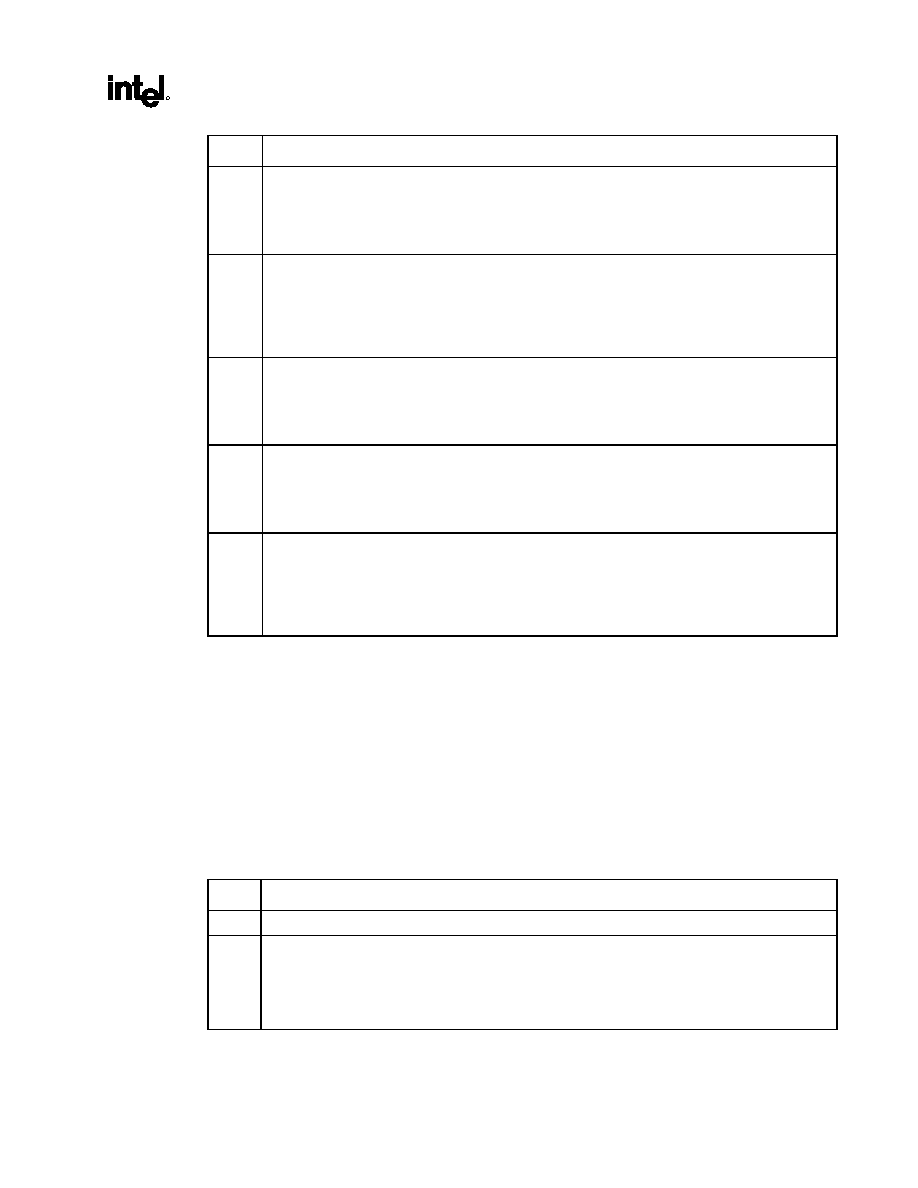
82840
MCH
R
Datasheet
75
Bit Description
4
SERR on AGP Access Outside of Graphics Aperture (OOGF_SERR)
1 = Enable. The generation of the hub interface A SERR message is enabled when an AGP access
occurs to an address outside of the graphics aperture.
0 = Disable
3
SERR on Invalid AGP Access (IAAF_SERR)
1 = Enable. The generation of the hub interface A SERR message is enabled when an AGP access
occurs to an address outside of the graphics aperture and either to the 640 KB ≠ 1 MB range or
above the top of memory.
0 = Disable
2
SERR on Invalid Translation Table Entry (ITTEF_SERR):
1 = Enable. The generation of the hub interface A SERR message is enabled when an invalid
translation table entry was returned in response to an AGP access to the graphics aperture.
0 = Disable
1
SERR Multiple-Bit DRAM ECC Error (DMERR_SERR):
1 = Enable. The generation of the hub interface A SERR message is enabled when the MCH DRAM
controller detects a multiple-bit error. For systems not supporting ECC, this bit must be disabled.
0 = Disable
0
SERR on Single-bit ECC Error (DSERR):
1 = Enable. When this bit is set, the generation of the hub interface A SERR message is enabled when
the MCH DRAM controller detects a single bit error. For systems not supporting ECC, this bit must
be disabled.
0 = Disable
3.4.38. SMICMD--SMI Command Register (Device 0)
Address Offset:
CC≠CDh
Default Value:
0000h
Access: Read/Write
Size: 16
bits
This register enables various errors to generate a SMI message via the hub interface A.
Note: An error can generate one and only one error message via the hub interface A. It is software's
responsibility to make sure that when an SMI error message is enabled for an error condition, SERR and
SCI error messages are disabled for that same error condition.
Bit Description
15:12 Reserved
11
SMI on Host Correctable Error (HCSMI):
1 = Enable. When this bit is set, the generation of the hub interface A SMI message is enabled when
the MCH has detected a correctable single-bit data error on the host bus.
0 = Disable. This bit must be set to a 0 if the systems does not implement the data correction on the
host bus.

76
Datasheet
Bit Description
10
SMI on External Thermal Sensor Trip (THERM_SMI):
1 = When this bit is set, the generation of the hub interface A SMI message is enabled when the MCH
has detected a rising edge on the OVERT# or the RDRAM devices report an overtemperature
conditions.
0 = Disable
9 Reserved
8
SMI on Target Abort on Hub interface B Exception (TAHLB_SMI):
1 = Enable. The generation of the hub interface A SMI message is enabled when an MCH originated
hub interface B cycle is completed with "Target Abort" status.
0 = Disable.
7
SMI on Hub interface B Unimplemented Special Cycle (UNSCB_SMI):
1 = Enable. The generation of the hub interface A SMI message is enabled when an MCH initiated hub
interface B request is terminated with a Unimplemented Special Cycle completion packet.
0 = Disable.
6
SMI on Target Abort on Hub interface A Exception (TAHLA_SMI):
1 = Enable. The generation of the hub interface A SMI message is enabled when an MCH originated
hub interface A cycle is completed with "Target Abort" status.
0 = Disable
5
SMI on Hub interface A Unimplemented Special Cycle (UNSCA_SMI):
1 = Enable. The generation of the hub interface A SMI message is enabled when an MCH initiated Hub
interface A request is terminated with a Unimplemented Special Cycle completion packet.
0 = Disable
4
SMI on AGP Access Outside of Graphics Aperture (OOGF_SMI):
1 = Enable. The generation of the hub interface A SMI message is enabled when an AGP access
occurs to an address outside of the graphics aperture.
0 = Disable.
3
SMI on Invalid AGP Access (IAAF_SMI):
1 = Enable. The generation of the hub interface A SMI message is enabled when an AGP access
occurs to an address outside of the graphics aperture and either to the 640 KB ≠ 1 MB range or
above the top of memory.
0 = Disable.
2
SMI on Invalid Translation Table Entry (ITTEF_SMI):
1 = Enable. When this bit is set, the generation of the hub interface A SMI message is enabled when
an invalid translation table entry was returned in response to an AGP access to the graphics
aperture.
0 = Disable.
1
SMI on Multiple-Bit DRAM ECC Error (DMERR_SMI):
1 = Enable. The generation of the hub interface A SMI message is enabled when the MCH DRAM
controller detects a multiple-bit error.
0 = Disable. For systems not supporting ECC this bit must be disabled.
0
SMI on Single-bit ECC Error (DSERR_SMI):
1 = Tthe generation of the hub interface A SMI message is enabled when the MCH DRAM controller
detects a single bit error.
0 = Disable. For systems that do not support ECC, this bit must be disabled.

82840
MCH
R
Datasheet
77
3.4.39. SCICMD--SCI Command Register (Device 0)
Address Offset:
CE≠CFh
Default Value:
0000h
Access: Read/Write
Size: 16
bits
This register enables various errors to generate a SCI message via the hub interface A.
Note: An error can generate one and only one error message via the hub interface A. It is software's
responsibility to make sure that when an SCI error message is enabled for an error condition, SERR and
SMI error messages are disabled for that same error condition.
Bit Description
15:13 Reserved
12
SCI on Host Uncorrectable Error (HUCSCI):
1 = Enable. The generation of the hub interface A SCI message is enabled when the MCH detects the
BERR# or the IERR# error condition on the front side bus.
0 = Disable.
11
SCI on Host Correctable Error (HCSCI):
1 = Enable. The generation of the hub interface A SCI message is enabled when the MCH has
detected a correctable single-bit data error on the host bus.
0 = Disable. This bit must be set to a 0 if the systems does not implement the data correction on the
host bus.
10
SCI on External Thermal Sensor Trip (THERM_SCI):
1 = Enable. The generation of the hub interface A SCI message is enabled when the MCH has
detected a rising edge on the OVERT# or the RDRAM devices report an overtemperature
conditions.
0 = Disable.
9
SCI on LOCK to non-DRAM Memory Flag (LCKF_SCI):
1 = Enable. The generation of the hub interface A SCI message is enabled when a host initiated LOCK
cycle targeting non-DRAM memory space has occurred.
0 = Disable. If this bit is set to "0", then the reporting of this condition is disabled.
8
SCI on Target Abort on Hub interface B Exception (TAHLB_SCI):
1 = Enable. The generation of the hub interface A SCI message is enabled when an MCH originated
hub interface B cycle is completed with "Target Abort" status.
0 = Disable.
7
SCI on Hub interface B Unimplemented Special Cycle (UNSCB_SCI):
1 = Enable. The generation of the hub interface A SCI message is enabled when an MCH initiated hub
interface B request is terminated with a Unimplemented Special Cycle completion packet.
0 = Disable.
6
SCI on Target Abort on Hub interface A Exception (TAHLA_SCI):
1 = Enable. The generation of the hub interface A SCI message is enabled when an MCH originated
hub interface A cycle is completed with "Target Abort" status.
0 = Disable.
5
SCI on Hub interface A Unimplemented Special Cycle (UNSCA_SCI):
1 = Enable. The generation of the hub interface A SCI message is enabled when an MCH initiated Hub
interface A request is terminated with a Unimplemented Special Cycle completion packet.
0 = Disable.

78
Datasheet
Bit Description
4
SCI on AGP Access Outside of Graphics Aperture (OOGF_SCI):
1 = Enable. The generation of the hub interface A SCI message is enabled when an AGP access
occurs to an address outside of the graphics aperture.
0 = Disable.
3
SCI on Invalid AGP Access (IAAF_SCI):
1 = Enable. The generation of the hub interface A SCI message is enabled when an AGP access
occurs to an address outside of the graphics aperture and either to the 640 KB ≠ 1 MB range or
above the top of memory.
0 = Disable.
2
SCI on Invalid Translation Table Entry (ITTEF_SCI):
1 = Enable. The generation of the hub interface A SCI message is enabled when an invalid translation
table entry was returned in response to an AGP access to the graphics aperture.
0 = Disable.
1
SCI on Multiple-Bit DRAM ECC Error (DMERR_SCI):
1 = Enable. The generation of the hub interface A SCI message is enabled when the MCH DRAM
controller detects a multiple-bit error.
0 = Disable. For systems not supporting ECC, this bit must be disabled.
0
SCI on Single-bit ECC Error (DSERR_SCI):
1 = Enable. The generation of the hub interface A SCI message is enabled when the MCH DRAM
controller detects a single bit error.
0 = Disable. For systems that do not support ECC, this bit must be disabled.
3.4.40. SKPD--Scratchpad Data (Device 0)
Address Offset:
DE≠DFh
Default Value:
0000h
Access: Read/Write
Size: 16
bits
Bit Description
15:0
Scratchpad [15:0]: These bits are simply R/W storage bits that have no effect on the MCH
functionality.

82840
MCH
R
Datasheet
79
3.4.41. HERRCTL_STS--Host Error Control/Status Register (Device 0)
Address Offset:
E0≠E1h
Default Value:
0000h
Access:
Read/Write, Read/Write Clear
Size: 16
bits
This register enables and reflects the status of various errors checking functions which the MCH supports
on the front side bus.
Bit Description
15
Detected BERR (DBERR)--R/WC:
1 = MCH detected a BERR# error condition on the host bus.
0 = Software must write a 1 to this field to clear it.
14
Detected IERR (DIERR)--R/WC:
1 = MCH detected an IERR# error condition on the host bus.
0 = Software must write a 1 to this field to clear it.
13:12 Reserved
11
Host Bus BERR# and IERR# Enable (BIERREN)--R/W:
1 = Enable. The detection of either a BERR or an IERR signal on the host bus is enabled. The type of
message sent is controlled by the ERRCMD, SCICMD, and SMICMD registers.
0 = Disable.
10
Host Bus Multiple Bit Error (HUCERR)--R/WC:
1 = MCH detected an uncorrectable error on the host bus.
0 = Software must write a 1 to this bit to clear it.
9
Host Bus BERR# Enable (HUCBERR)--R/W:
1 = Enable. Generation of the host bus BERR signal when the MCH detects an uncorrectable error on
the host bus data pins is enabled.
0 = Disable.
8
Host Bus ECC Generation Strapping Status (HECCSS)--RO: This bit reflects the status of the MCH
strapping option of enabling the error correcting codes generation for host bus transactions.
1 = Enable (via strapping option)
0 = Disable (via strapping option)
7:0
Host Bus ECC Syndrome (HECCSYN)--RO: After a host bus ECC error, hardware loads this field
with a syndrome that describes the set of bits found to be in error. Note that this field is locked from the
time that it is loaded to the time when it is read by software. If the first error was a single bit, correctable
error, then a subsequent multiple bit error will overwrite this field. In all other cases, an error which
occurs after the first error and before the register has been read by software will escape recording.

80
Datasheet
3.4.42. DERRCTL_STS--DRAM Error Control/Status Register
(Device 0)
Address Offset:
E2≠E3h
Default Value:
0000h
Access:
Read Only, Read/Write Clear
Size: 16
bits
This register enables and reflects the status of various errors checking functions which the MCH supports
on the DRAM interface.
Bit Description
15:12 Reserved
11
DRAM Correctable ECC Error (DCERR)--R/WC:
1 = MCH detected a correctable error on the DRAM Interface.
0 = It is cleared by writing 1 to it or when an uncorrectable error is detected on the bus.
10
DRAM Multiple Bit Error (DUCERR)--R/WC:
1 = MCH detected an uncorrectable error on the DRAM interface.
0 = It is cleared by writing 1 to it.
9:8 Reserved
7:0
DRAM ECC Syndrome (DECCSYN)--RO: After a DRAM ECC error, hardware loads this field with a
syndrome that describes the set of bits found to be in error. Note that this field is locked from the time
that it is loaded up to the time when it is read by software. If the first error was a single bit, correctable
error, then a subsequent multiple bit error will overwrite this field. In all other cases, an error which
occurs after the first error and before the register has been read by software will escape recording.
3.4.43. EAP--Error Address Pointer Register (Device 0)
Address Offset:
E4≠E7h
Default Value:
0000h
Access: Read
Only
Size: 32
bits
This register stores the DRAM address when an ECC error occurs.
Bit Description
31:11
Error Address Pointer (EAP)--RO: This field is used to store the 4 KB block of main memory where
an error (single bit or multi-bit error) has occurred. Note that the value of this bit field represents the
address of the first single or the first multiple bit error occurrence after the error flag bits in the ERRSTS
register have been cleared by software. A multiple bit error will overwrite a single bit error.
Once the error flag bits are set as a result of an error, this bit field is locked and doesn't change as a
result of a new error.
10:1 Reserved
0
Error Address Segment (EAS)--RO: This bit indicates whether the reported error was found on
Rambus* channel 0 or on channel 1.
1 = Channel 1
0 = Channel 0

82840
MCH
R
Datasheet
81
3.4.44. AGPBCTRL--AGP Buffer Strength Control Register
Address Offset:
E8≠EBh
Default Value:
0000h
Access: Read/Write
Size: 32
bits
This register controls the 3.3V AGP buffer strength. The proper setting is documented in the Intel
840
BIOS Specification Update.
Bit Description
31:24
AGP Buffer Strength Control 1:
23:16
AGP Buffer Strength Control 2:.
15:0 Reserved
3.4.45. AGPAPPEND--AGP Append Disable Register
Address Offset:
F6h
Default Value:
00h
Access: Read/Write
Size: 8
bits
This register controls the AGP interface.
Bit Description
7:6 Reserved
5
AGP Append Disable:
1 = Disable CPU-to-AGP Write Appending
0 = Enable (default).
4:0
Reserved
3.4.46. GTLNCLAMP--GTL N Clamp Disable Register
Address Offset:
F7h
Default Value:
00h
Access: Read/Write
Size: 8
bits
Bit Description
7 Reserved
6:5
GTL N-Clamp Disable Register:
10 = Disable.
4:0 Reserved

82
Datasheet
3.5.
AGP Bridge Registers (Device 1)
Table 5 summarizes the MCH configuration space for Device 1.
Table 5. MCH Configuration Space (Device 1)
Address
Offset
Symbol Register
Name Default
Value
Access
00≠01h VID1
Vendor
Identification
8086h RO
02≠03h DID1
Device
Identification
1A23h RO
04≠05h PCICMD1
PCI
Command
Register
0000h R/W
06≠07h
PCISTS1
PCI Status Register
0020h
RO, R/WC
08 RID1
Revision
Identification
00h
RO
09
Reserved
00h
0Ah SUBC1
Sub-Class
Code
04h RO
0Bh
BCC1
Base Class Code
06h
RO
0Ch
Reserved
00h
0Dh MLT1
Master
Latency
Timer
00h R/W
0Eh HDR1
Header
Type
01h RO
0F≠17h
Reserved
00h
18h PBUSN1
Primary
Bus
Number
00h RO
19h
SBUSN1
Secondary Bus Number
F0h
R/W
1Ah SUBUSN1
Subordinate
Bus
Number
00h R/W
1Bh
SMLT1
Secondary Bus Master Latency Timer
00h
R/W
1Ch
IOBASE1
I/O Base Address Register
00h
R/W
1Dh
IOLIMIT1
I/O Limit Address Register
00h
R/W
1E≠1Fh
SSTS1
Secondary Status Register
02A0h
RO, R/WC
20≠21h
MBASE1
Memory Base Address Register
FFF0h
R/W
22≠23h
MLIMIT1
Memory Limit Address Register
0000h
R/W
24≠25h
PMBASE1
Prefetchable Memory Base Address Reg.
FFF0h
R/W
26≠27h
PMLIMIT1
Prefetchable Memory Limit Address Reg.
0000h
R/W
28≠3Dh
Reserved
3Eh
BCTRL1
Bridge Control Register
00h
R/W
3Fh
Reserved
40h ERRCMD1
Error
Command
00h R/W
41≠FFh
Reserved

82840
MCH
R
Datasheet
83
3.5.1.
VID1--Vendor Identification Register (Device 1)
Address Offset:
00≠01h
Default Value:
8086h
Attribute: Read
Only
Size: 16
bits
The VID Register contains the vendor identification number. This 16-bit register combined with the
Device Identification Register uniquely identify any PCI device. Writes to this register have no effect.
Bit Description
15:0
Vendor Identification Number: This is a 16-bit value assigned to Intel. Intel VID = 8086h.
3.5.2.
DID1--Device Identification Register (Device 1)
Address Offset:
02≠03h
Default Value:
1A23h
Attribute: Read
Only
Size: 16
bits
This 16-bit register combined with the Vendor Identification register uniquely identifies any PCI device.
Writes to this register have no effect.
Bit Description
15:0
Device Identification Number: This is a 16 bit value assigned to the MCH Device 1.
The MCH Device 1 DID = 1A23h.

84
Datasheet
3.5.3.
PCICMD1--PCI-PCI Command Register (Device 1)
Address Offset:
04≠05h
Default: 0000h
Access:
Read Only, Read/Write
Size 16
bits
Bit Descriptions
15:10 Reserved
9
Fast Back-to-Back--RO: (Not Applicable). Hardwired to 0.
8
SERR Message Enable (SERRE1)--R/W. This bit is a global enable bit for Device 1 SERR
messaging. The MCH does not have an SERR# signal. The MCH communicates the SERR# condition
by sending an SERR message to the ICH.
1 = Enable. The MCH is enabled to generate SERR messages over the hub interface for specific
Device 1 error conditions that are individually enabled in the BCTRL register. The error status is
reported in the PCISTS1 register.
0 = Disable. The SERR message is not generated by the MCH for Device 1.
NOTE: This bit only controls SERR messaging for the Device 1. Device 0 has its own SERRE bit to
control error reporting for error conditions occurring on Device 0.
7
Address/Data Stepping--RO: (Not applicable). Hardwired to 0.
6
Parity Error Enable (PERRE1)-- RO: PERR# is not supported on AGP. Hardwired to 0.
5 Reserved
4
Memory Write and Invalidate Enable--RO: (Not Implemented). Hardwired to 0.
3
Special Cycle Enable--RO: (Not Implemented). Hardwired to 0.
2
Bus Master Enable (BME1)-- R/W:
1 = Enable. AGP Master initiated FRAME# cycles will be accepted by the MCH, if they hit a valid
address decode range.
0 = Disable (default). AGP Master initiated FRAME# cycles will be ignored by the MCH resulting in a
Master Abort.
Note that incoming configuration cycles still need to be accepted regardless of the setting of this Bus
Master Enable bit. This bit has no affect on AGP Master originated SBA or PIPE# cycles.
1
Memory Access Enable (MAE1)--R/W:
1 = Enable. This bit must be 1 to enable the Memory and Prefetchable memory address ranges
defined in the MBASE1, MLIMIT1, PMBASE1, and PMLIMIT1 registers.
0 = Disable. All of Device 1's memory space is disabled.
0
I/O Access Enable (IOAE1)-- R/W: This bit must be set to1 to enable the I/O address range defined
in the IOBASE1, and IOLIMIT1 registers. When set to 0 all of Device 1's I/O space is disabled.

82840
MCH
R
Datasheet
85
3.5.4.
PCISTS1--PCI-PCI Status Register (Device 1)
Address Offset:
06≠07h
Default Value:
0000h
Access:
Read Only, Read/Write Clear
Size: 16
bits
PCISTS1 is a 16-bit status register that reports the occurrence of error conditions associated with the
primary side of the "virtual" PCI-PCI bridge in the MCH. Since this device does not physically reside on
PCI_A, it reports the optimum operating conditions so that it does not restrict the capability of PCI_A.
Bit Descriptions
15
Detected Parity Error (DPE1)--RO: (Not Applicable). Hardwired to 0.
14
Signaled System Error (SSE1)--R/WC:
1 = MCH Device 1 generates an SERR message over the hub interface A for any enabled Device 1
error condition. Device 1 error conditions are enabled in the PCICMD1 and BCTRL1 registers.
Device 1 error flags are read/reset from the SSTS1 register.
0 = Software clears this bit by writing a 1 to it.
13
Received Master Abort Status (RMAS1)-- RO: (Not Applicable). Hardwired to 0.
12
Received Target Abort Status (RTAS1) --RO: (Not Applicable). Hardwired to 0.
11
Signaled Target Abort Status (STAS1) (RO): (Not Applicable). Hardwired to 0.
10:9
DEVSEL# Timing (DEVT1): This bit field is hardwired to "00b" to indicate that the Device 1 uses the
fastest possible decode.
8
Data Parity Detected (DPD1)--RO: Parity is not supported on AGP port. Hardwired to 0.
7
Fast Back-to-Back (FB2B1)--RO: AGP port always supports fast back to back transactions.
Hardwired to 1.
6 Reserved.
5
33/66 MHz Capability--RO: AGP port is 66 MHz capable. Hardwired to 1.
4:0 Reserved.
3.5.5.
RID1--Revision Identification Register (Device 1)
Address Offset:
08h
Default Value:
00h
Access: Read
Only
Size: 8
bits
This register contains the revision number of the MCH device 1. These bits are read only and writes to
this register have no effect. For the A-0 Stepping, this value is 00h.
Bit Description
7:0
Revision Identification Number: This is an 8-bit value that indicates the revision identification number
for the MCH Device 1.

86
Datasheet
3.5.6.
SUBC1--Sub-Class Code Register (Device 1)
Address Offset:
0Ah
Default Value:
04h
Access: Read
Only
Size: 8
bits
This register contains the Sub-Class Code for the MCH device 1.
Bit Description
7:0
Sub-Class Code (SUBC1): This is an 8-bit value that indicates the category of Bridge for the MCH.
04h = PCI-to-PCI Bridge.
3.5.7.
BCC1--Base Class Code Register (Device 1)
Address Offset:
0Bh
Default Value:
06h
Access: Read
Only
Size: 8
bits
This register contains the Base Class Code of the MCH device 1.
Bit Description
7:0
Base Class Code (BASEC): This is an 8-bit value that indicates the Base Class Code for the MCH
device 1.
06h = Bridge device.
3.5.8.
MLT1--Master Latency Timer Register (Device 1)
Address Offset:
0Dh
Default Value:
00h
Access: Read/Write
Size: 8
bits
This functionality is not applicable. It is described here since these bits should be implemented as a
read/write to prevent standard PCI-PCI bridge configuration software from getting "confused" .
Bit Description
7:3
Not applicable but support read/write operations. (Reads return previously written data.)
2:0 Reserved.
3.5.9.
HDR1--Header Type Register (Device 1)
Offset: 0Eh
Default: 01h
Access: Read
Only
Size: 8
bits
This register identifies the header layout of the configuration space.
Bit Descriptions
7:0
Header Type: Hardwired to 01h.

82840
MCH
R
Datasheet
87
3.5.10. PBUSN1--Primary Bus Number Register (Device 1)
Offset: 18h
Default: 00h
Access: Read
Only
Size: 8
bits
This register identifies that "virtual" PCI-PCI bridge is connected to bus #0.
Bit Descriptions
7:0
Primary Bus Number: Hardwired to 00h.
3.5.11. SBUSN1--Secondary Bus Number Register (Device 1)
Offset: 19h
Default: 00h
Access: Read
/Write
Size: 8
bits
This register identifies the bus number assigned to the second bus side of the "virtual" PCI-PCI bridge
(i.e., to AGP). This number is programmed by the PCI configuration software to allow mapping of
configuration cycles to AGP.
Bit Descriptions
7:0
Secondary Bus Number: Programmable. Default=00h.
3.5.12. SUBUSN1--Subordinate Bus Number Register (Device 1)
Offset: 1Ah
Default: 00h
Access: Read
/Write
Size: 8
bits
This register identifies the subordinate bus (if any) that resides at the level below AGP. This number is
programmed by the PCI configuration software to allow mapping of configuration cycles to AGP.
Bit Descriptions
7:0
Subordinate Bus Number: Programmable. Default = 0.

88
Datasheet
3.5.13. SMLT1--Secondary Master Latency Timer Register (Device 1)
Address Offset:
1Bh
Default Value:
00h
Access: Read/Write
Size: 8
bits
This register controls the bus tenure of the MCH on AGP. SMLT1 controls the amount of time the MCH,
as a AGP/PCI bus master, can burst data on the AGP Bus. The Count Value is an 8 bit quantity;
however, MLT[2:0] are reserved and assumed to be 0 when determining the Count Value. The SMLT1 is
used to guarantee to the AGP master a minimum amount of the system resources. When the MCH begins
the first AGP FRAME# cycle after being granted the bus, the counter is loaded and enabled to count
from the assertion of FRAME#. If the count expires while the MCH's grant is removed (due to AGP
master request), the MCH loses the use of the bus, and the AGP master agent may be granted the bus. If
the MCH's bus grant is not removed, the MCH continues to own the AGP bus, regardless of the SMLT1
expiration or idle condition. Note that the MCH must always properly terminate an AGP transaction,
with FRAME# negation prior to the final data transfer.
The number of clocks programmed in the SMLT1 represents the guaranteed time slice (measured in
66 MHz AGP clocks) allotted to the MCH, after which it must complete the current data transfer phase
and then surrender the bus as soon as its bus grant is removed. For example, if the SMLT1 is
programmed to 18h, then the value is 24 AGP clocks. The default value of 00h disables this function.
When the SMLT1 is disabled, the burst time for the MCH is unlimited (i.e., the MCH can burst forever).
Bit Description
7:3
Secondary MLT Counter Value: Default=0 (i.e., SMLT1 disabled)
2:0 Reserved.
3.5.14. IOBASE1--I/O Base Address Register (Device 1)
Address Offset:
1Ch
Default Value:
F0h
Access: Read/Write
Size: 8
bits
This register control the host to AGP I/O access routing based on the following formula:
IO_BASE
address
IO_LIMIT
Only the upper 4 bits are programmable. For the purpose of address decode, address bits A[11:0] are
treated as 0. Thus, the bottom of the defined I/O address range will be aligned to a 4 KB boundary.
Note: BIOS must not set this register to 00h; otherwise, 0CF8h/0CFCh accesses will be forwarded to AGP.
Bit Description
7:4
I/O Address Base: Corresponds to A[15:12] of the I/O address. Default=F0h
3:0 Reserved.
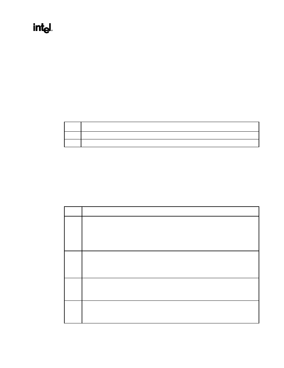
82840
MCH
R
Datasheet
89
3.5.15. IOLIMIT1--I/O Limit Address Register (Device 1)
Address Offset:
1Dh
Default Value:
00h
Access: Read/Write
Size: 8
bits
This register controls the host to AGP I/O access routing based on the following formula:
IO_BASE
address
IO_LIMIT
Only the upper 4 bits are programmable. For the purpose of address decode, address bits A[11:0] are
assumed to be FFFh. Thus, the top of the defined I/O address range will be at the top of a 4 KB aligned
address block.
Bit Description
7:4
I/O Address Limit: Corresponds to A[15:12] of the I/O address. Default=0
3:0
Reserved. (Only 16 bit addressing supported.)
3.5.16. SSTS1--Secondary PCI-PCI Status Register (Device 1)
Address Offset:
1E≠1Fh
Default Value:
02A0h
Access:
Read Only, Read/Write Clear
Size: 16
bits
SSTS is a 16-bit status register that reports the occurrence of error conditions associated with the
secondary side (i.e., AGP side ) of the "virtual" PCI-PCI bridge in the MCH.
Bit Descriptions
15
Detected Parity Error (DPE1)--R/WC:
1 = MCH detected a parity error in the address or data phase of AGP bus transactions.
0 = Software sets DPE1 to 0 by writing a 1 to this bit.
Note that the function of this bit is not affected by the PERRE1 bit. Also note that PERR# is not
implemented in the MCH.
14
Received System Error (SSE1)--R/WC:
1 = MCH generates an SERR message for any enabled error condition under device 1. Device 1 error
conditions are enabled in the BCTRL1 register.
0 = Software clears SSE1 to 0 by writing a 1 to this bit.
13
Received Master Abort Status (RMAS1)--R/WC:
1 = MCH terminates a Host-to-AGP with an unexpected master abort.
0 = Software resets this bit to 0 by writing a 1 to it.
12
Received Target Abort Status (RTAS1)--R/WC:
1 = MCH-initiated transaction on AGP is terminated with a target abort.
0 = Software resets RTAS1 to 0 by writing a 1 to it.

90
Datasheet
Bit Descriptions
11
Signaled Target Abort Status (STAS1)--RO: MCH does not generate target abort on AGP.
Hardwired to a 0.
10:9
DEVSEL# Timing (DEVT1)--RO: This 2-bit field indicates the timing of the DEVSEL# signal when the
MCH responds as a target on AGP, and is hardwired to the value 01b (medium) to indicate the time
when a valid DEVSEL# can be sampled by the initiator of the PCI cycle.
8
Data Parity Detected (DPD1)--RO: (Not Implemented): Hardwired to 0. MCH does not implement
G_PERR# function. However, data parity errors are still detected and reported via the hub interface A
(if enabled by SERRE1 bit of the PCICMD1 register and bit 0 of the BCTRL register).
7
Fast Back-to-Back (FB2B1)--RO: MCH, as a target, supports fast back-to-back transactions on AGP.
Hardwired to 1.
6 Reserved
5
33/66 MHz Capable (CAP66)--RO: AGP bus is capable of 66 MHz operation. Hardwired to 1.
4:0 Reserved.
3.5.17. MBASE1--Memory Base Address Register (Device 1)
Address Offset:
20≠21h
Default Value:
FFF0h
Access: Read/Write
Size: 16
bits
This register controls the host to AGP non-prefetchable memory access routing based on the following
formula:
MEMORY_BASE1
address
MEMORY_LIMIT1
The upper 12 bits of this register are read/write and correspond to the upper 12 address bits A[31:20] of
the 32 bit address. The lower 4 bits of this register are read-only and return zeroes when read. This
register must be initialized by configuration software. For the purpose of address decode, address bits
A[19:0] are assumed to be 0. Thus, the bottom of the defined memory address range will be aligned to a
1 MB boundary.
Bit Description
15: 4
Memory Address Base 1 (MEM_BASE1): Corresponds to A[31:20] of the memory address.
3:0 Reserved.

82840
MCH
R
Datasheet
91
3.5.18. MLIMIT1--Memory Limit Address Register (Device 1)
Address Offset:
22≠23h
Default Value:
0000h
Access: Read/Write
Size: 16
bits
This register controls the host to AGP non-prefetchable memory access routing based on the following
formula:
MEMORY_BASE1
address
MEMORY_LIMIT1
The upper 12 bits of the register are read/write and correspond to the upper 12 address bits A[31:20] of
the 32 bit address. The lower 4 bits of this register are read-only and return zeroes when read. This
register must be initialized by the configuration software. For the purpose of address decode, address bits
A[19:0] are assumed to be FFFFFh. Thus, the top of the defined memory address range will be at the top
of a 1 MB aligned memory block.
Bit Description
15: 4
Memory Address Limit 1(MEM_LIMIT1): Corresponds to A[31:20] of the memory address. Default=0
3:0 Reserved.
Note: Memory range covered by MBASE1 and MLIMIT1 registers are used to map non-prefetchable AGP
address ranges (typically, where control/status memory-mapped I/O data structures of the graphics
controller will reside) and PMBASE 1and PMLIMIT1 are used to map prefetchable address ranges
(typically, graphics local memory). This segregation allows application of USWC space attribute to be
performed in a true plug-and-play manner to the prefetchable address range for improved host-AGP
memory access performance.
3.5.19. PMBASE1--Prefetchable Memory Base Address Register
(Device 1)
Address Offset:
24≠25h
Default Value:
FFF0h
Access: Read/Write
Size: 16
bits
This register controls the host to AGP prefetchable memory accesses routing based on the following
formula:
PREFETCHABLE_MEMORY_BASE1
address
PREFETCHABLE_MEMORY_LIMIT1
The upper 12 bits of the register are read/write and correspond to the upper 12 address bits A[31:20] of
the 32 bit address. The lower 4 bits of this register are read-only and return zeroes when read. This
register must be initialized by the configuration software. For the purpose of address decode, address bits
A[19:0] are assumed to be 0. Thus, the bottom of the defined memory address range will be aligned to a
1 MB boundary.
Bit Description
15: 4
Prefetchable Memory Address Base 1(PMEM_BASE1): Corresponds to A[31:20] of the memory
address.
3:0 Reserved.

92
Datasheet
3.5.20. PMLIMIT1--Prefetchable Memory Limit Address Register
(Device 1)
Address Offset:
26≠27h
Default Value:
0000h
Access: Read/Write
Size: 16
bits
This register controls the host to AGP prefetchable memory accesses routing based on the following
formula:
PREFETCHABLE_MEMORY_BASE1
address
PREFETCHABLE_MEMORY_LIMIT1
The upper 12 bits of the register are read/write and correspond to the upper 12 address bits A[31:20] of
the 32 bit address. The lower 4 bits of this register are read-only and return zeroes when read. This
register must be initialized by the configuration software. For the purpose of address decode, address bits
A[19:0] are assumed to be FFFFFh. Thus, the top of the defined memory address range will be at the top
of a 1 MB aligned memory block.
Note: A prefetchable memory range is supported to allow segregation by the configuration software between
the memory ranges that must be defined as UC and the ones that can be designated as a USWC (i.e.,
prefetchable) from the processor perspective.
Bit Description
15: 4
Prefetchable Memory Address Limit 1(PMEM_LIMIT1): Corresponds to A[31:20] of the memory
address. Default=0
3:0 Reserved.
3.5.21. BCTRL1--PCI-PCI Bridge Control Register (Device 1)
Address Offset:
3Eh
Default: 00h
Access:
Read Only, Read/Write
Size 8
bits
This register provides extensions to the PCICMD1 register that are specific to PCI-PCI bridges. The
BCTRL provides additional control for the secondary interface (i.e., AGP) as well as some bits that
affect the overall behavior of the "virtual" PCI-PCI bridge embedded within MCH (e.g., VGA
compatible address ranges mapping).

82840
MCH
R
Datasheet
93
Bit Descriptions
7
Fast Back to Back Enable--RO: Since there is only one target allowed on AGP this bit is
meaningless.Hardwired to 0. The MCH will not generate FB2B cycles in 1x mode, but will generate
FB2B cycles in 2x and 4x Fast Write modes.
6
Secondary Bus Reset--RO: MCH does not support generation of reset via this bit on the AGP.
Hardwired to 0.
Note that the only way to perform a hard reset of the AGP is via the system reset either initiated by
software or hardware via ICH.
5
Master Abort Mode--RO: Hardwired to 0. This means when acting as a master on AGP the MCH will
discard data on writes and return all 1s during reads when a Master Abort occurs.
4 Reserved
3
VGA Enable (VGAEN1)--R/W: Controls the routing of host, hub interface A, and hub interface B
initiated transactions targeting VGA compatible I/O and memory address ranges.
1 = Enable. MCH forwards the following host accesses to the AGP:
∑
memory accesses in the range 0A0000h≠0BFFFFh
∑
I/O addresses where A[9:0] are in the ranges 3B0h≠3BBh and 3C0h≠3DFh
(inclusive of ISA address aliases; A[15:10] are not decoded)
When enabled, forwarding of these accesses issued by the host is independent of the I/O address
and memory address ranges defined by the previously defined base and limit registers. Forwarding
of these accesses is also independent of the settings of bit 2 (ISA Enable) of this register, if this bit
is 1.
0 = Disable. VGA compatible memory and I/O range accesses are not forwarded to AGP; rather, they
are mapped to primary PCI unless they are mapped to AGP via I/O and memory range registers
defined above (IOBASE1, IOLIMIT1, MBASE1, MLIMIT1, PMBASE1, PMLIMIT1)
Refer to the System Address Map Chapter for further information.
2
ISA Enable --R/W: Modifies the response by the MCH to an I/O access issued by the host that
targets ISA I/O addresses. This applies only to I/O addresses that are enabled by the IOBASE and
IOLIMIT registers.
1 = MCH will not forward to AGP any I/O transactions addressing the last 768 bytes in each 1 KB
block, even if the addresses are within the range defined by the IOBASE and IOLIMIT registers.
Instead of going to AGP these cycles are forwarded to PCI0 where they can be subtractively or
positively claimed by the ISA bridge.
0 = Disable (default). All addresses defined by the IOBASE and IOLIMIT for host I/O transactions are
mapped to AGP.
1
SERR# Enable (SERRE)--R/W: This bit controls the forwarding of SERR# on the secondary interface
to the primary interface.
1= Enable SERRE. MCH generates SERR messages to hub interface A when the SERR# pin on AGP
bus is asserted and when the messages are enabled by the SERRE1 bit in the PCICMD1 register.
0 = Disable.
0
Parity Error Response Enable--R/W: Controls MCH's response to data phase parity errors on AGP.
Note that G_PERR# is not implemented by the MCH.
1 = Address and data parity errors on AGP are reported via SERR# mechanism, if enabled by
SERRE1 and SERRE.
0 = Address and data parity errors on AGP are not reported via the MCH SERR# signal. Other types of
error conditions can still be signaled via SERR# independent of this bit's state.

94
Datasheet
3.5.22. ERRCMD1--Error Command Register (Device 1)
Address Offset:
40h
Default Value:
00h
Access: Read/Write
Size: 8
bits
Bit Description
7:1 Reserved
0
SERR on Receiving Target Abort (SERTA):
1 = MCH generates an SERR message over hub interface A upon receiving a target abort on AGP.
0 = MCH does not assert an SERR message upon receipt of a target abort on AGP. SERR messaging
for Device 1 is globally enabled in the PCICMD1 register.

82840
MCH
R
Datasheet
95
3.6.
Hub interface B Bridge Registers (Device 2)
Table 6 summarizes the MCH configuration space for device 2.
Table 6. MCH Configuration Space (Device 2)
Address
Offset
Symbol Register
Name
Default
Access
00≠01h
VID2
Vendor Identification
8086h
RO
02≠03h DID2
Device
Identification
1A24h RO
04≠05h PCICMD2
PCI
Command
Register
0000h
R/W
06≠07h
PCISTS2
PCI Status Register
0020h
RO, R/WC
08 RID2
Revision
Identification
00h RO
09
Reserved
00h
0Ah SUBC2
Sub-Class
Code
04h RO
0Bh BCC2
Base
Class
Code
06h RO
0Ch
Reserved
00h
0Dh MLT2
Master
Latency
Timer
00h R/W
0Eh HDR2
Header
Type
01h RO
0F≠17h
Reserved
00h
18h
PBUSN2
Primary Bus Number
00h
RO
19h
SBUSN2
Secondary Bus Number
00h
R/W
1Ah
SUBUSN2
Subordinate Bus Number
00h
R/W
1Bh
SMLT2
Secondary Bus Master Latency Timer
00h
R/W
1Ch
IOBASE2
I/O Base Address Register
F0h
R/W
1Dh
IOLIMIT2
I/O Limit Address Register
00h
R/W
1E≠1Fh
SSTS2
Secondary Status Register
02A0h
RO, R/WC
20≠21h
MBASE2
Memory Base Address Register
FFF0h
R/W
22≠23h
MLIMIT2
Memory Limit Address Register
0000h
R/W
24≠25h
PMBASE2
Prefetchable Memory Base Address Reg.
FFF0h
R/W
26≠27h
PMLIMIT2
Prefetchable Memory Limit Address Reg.
0000h
R/W
28≠3Dh
Reserved
3Eh BCTRL2
Bridge
Control
Register
00h R/W
3Fh
Reserved
40h ERRCMD2
Error
Command
00h
R/W
41≠FFh
Reserved

96
Datasheet
3.6.1.
VID2--Vendor Identification Register (Device 2)
Address Offset:
00≠01h
Default Value:
8086h
Attribute: Read
Only
Size: 16
bits
The VID Register contains the vendor identification number. This 16-bit register combined with the
Device Identification Register uniquely identify any PCI device. Writes to this register have no effect.
Bit Description
15:0
Vendor Identification Number: This is a 16-bit value assigned to Intel. Intel VID = 8086h.
3.6.2.
DID2--Device Identification Register (Device 2)
Address Offset:
02≠03h
Default Value:
1A24h
Attribute: Read
Only
Size: 16
bits
This 16-bit register combined with the Vendor Identification register uniquely identifies any PCI device.
Writes to this register have no effect.
Bit Description
15:0
Device Identification Number: This is a 16 bit value assigned to the MCH Device 2.
The MCH Device 2 DID = 1A24h.

82840
MCH
R
Datasheet
97
3.6.3.
PCICMD2--PCI-PCI Command Register (Device 2)
Address Offset:
04
≠
05h
Default: 0000h
Access:
Read Only, Read/Write
Size 16
bits
Bit Descriptions
15:10 Reserved.
9
Fast Back-to-Back--RO: (Not applicable). Hardwired to 0.
8
SERR Message Enable (SERRE2)--R/W: This bit is a global enable bit for Device 2 SERR
messaging. The MCH does not have an SERR# signal. The MCH communicates the SERR# condition
by sending an SERR message to the ICH.
1 = Enable. MCH is enabled to generate SERR messages over the hub interface A for specific
Device 2 error conditions that are individually enabled in the BCTRL2 register. The error status is
reported in the PCISTS2 register.
0 = SERR message is not generated by the MCH for Device 2.
NOTE: This bit only controls SERR messaging for the Device 2. Device 0 has its own SERRE bit to
control error reporting for error conditions occurring on Device 0.
7
Address/Data Stepping--RO: (Not applicable). Hardwired to 0.
6
Parity Error Enable (PERRE2)--R/W: (Not applicable). Supported as a read/write bit to avoid issues
with standard PCI-PCI Bridge configuration software.
5 Reserved.
4
Memory Write and Invalidate Enable--R/W: (Not applicable). Supported as a read/write bit to avoid
issues with standard PCI-PCI Bridge configuration software.
3
Special Cycle Enable--R/W: (Not applicable). Supported as a read/write bit to avoid issues with
standard PCI-PCI Bridge configuration software.
2
Bus Master Enable (BME2)--R/W:
1 = Enable. Device#2 (virtual P2P bridge) operates as a master on the primary interface on behalf of a
master on the secondary interface for memory or I/O transaction.
0 = Disable. Device 2 disables response to all memory or I/O transactions on the secondary interface.
1
Memory Access Enable (MAE2)--R/W: (Not applicable). Supported as a read/write bit to avoid
issues with standard PCI-PCI Bridge configuration software.
0
I/O Access Enable (IOAE2)--R/W: (Not applicable). Supported as a read/write bit to avoid issues
with standard PCI-PCI Bridge configuration software.

98
Datasheet
3.6.4.
PCISTS2--PCI-PCI Status Register (Device 2)
Address Offset:
06≠07h
Default Value:
00A0h
Access:
Read Only, Read/Write Clear
Size: 16
bits
PCISTS2 reports the occurrence of error conditions associated with the primary side of the "virtual" PCI-
PCI bridge in the MCH. Since this device does not physically reside on PCI_A, it reports the optimum
operating conditions so that it does not restrict the capability of PCI_A.
Bit Descriptions
15
Detected Parity Error (DPE2)--RO: (Not Applicable). Hardwired to 0.
14
Signaled System Error (SSE2)--R/WC:
1 = MCH Device 2 generates an SERR message over the hub interface A for any enabled Device 2
error condition. Device 2 error conditions are enabled in the PCICMD2 and BCTRL2 registers.
Device 2 error flags are read/reset from the SSTS2 register.
0 = Software clears this bit by writing a 1 to it.
13
Received Master Abort Status (RMAS2)--RO: (Not Applicable). Hardwired to 0.
12
Received Target Abort Status (RTAS2)--RO: (Not Applicable). Hardwired to 0.
11
Signaled Target Abort Status (STAS2)--RO: (Not Applicable). Hardwired to 0.
10:9
DEVSEL# Timing (DEVT2)--RO: Device 2 uses the fastest possible decode. Hardwired to 00.
8
Data Parity Detected (DPD2)--RO: (Not Applicable). Hardwired to 0.
7
Fast Back-to-Back (FB2B2)--RO: Fast back-to-back writes are always supported. Hardwired to 1.
6 Reserved.
5
33/66 MHz Capability--RO: Capable of 66 MHz operation. Hardwired to 1.
4:0 Reserved.
3.6.5.
RID2--Revision Identification Register (Device 2)
Address Offset:
08h
Default Value:
00h
Access: Read
Only
Size: 8
bits
This register contains the revision number of the MCH Device 2. These bits are read only and writes to
this register have no effect.
Bit Description
7:0
Revision Identification Number: This is an 8-bit value that indicates the revision identification
number for the MCH Device 2.
A-0 Stepping = 00h.

82840
MCH
R
Datasheet
99
3.6.6.
SUBC2--Sub-Class Code Register (Device 2)
Address Offset:
0Ah
Default Value:
04h
Access: Read
Only
Size: 8
bits
This register contains the Sub-Class Code for the MCH Device 2.
Bit Description
7:0
Sub-Class Code (SUBC2): This is an 8-bit value that indicates the category of Bridge for the MCH.
04h = PCI-PCI Bridge.
3.6.7.
BCC2--Base Class Code Register (Device 2)
Address Offset:
0Bh
Default Value:
06h
Access: Read
Only
Size: 8
bits
This register contains the Base Class Code of the MCH Device 2.
Bit Description
7:0
Base Class Code (BASEC2): This is an 8-bit value that indicates the Base Class Code for the MCH
Device 2.
06h = Bridge device.
3.6.8.
MLT2--Master Latency Timer Register (Device 2)
Address Offset:
0Dh
Default Value:
00h
Access: Read/Write
Size: 8
bits
This functionality is not applicable. It is described here since these bits should be implemented as a
read/write to prevent issues with standard PCI-PCI bridge configuration software.
Bit Description
7:3
MLT Count Value: Not applicable but support read/write operations. (Reads return previously written
data.)
2:0 Reserved.
3.6.9.
HDR2--Header Type Register (Device 2)
Offset: 0Eh
Default: 01h
Access: Read
Only
Size: 8
bits
This register identifies the header layout of the configuration space.
Bit Descriptions
7:0
Header Type: This read only field always returns 01h when read. Writes have no effect.

100
Datasheet
3.6.10. PBUSN2--Primary Bus Number Register (Device 2)
Offset: 18h
Default: 00h
Access: Read
Only
Size: 8
bits
This register identifies that "virtual" PCI-PCI bridge is connected to bus #0.
Bit Descriptions
7:0
Primary Bus Number: Hardwired to 0.
3.6.11. SBUSN2--Secondary Bus Number Register (Device 2)
Offset: 19h
Default: 00h
Access: Read
/Write
Size: 8
bits
This register identifies the bus number assigned to the second bus side of the "virtual" PCI-PCI bridge
(the hub interface B connection). This number is programmed by the PCI configuration software to allow
mapping of configuration cycles to a second bridge device connected to hub interface B.
Bit Descriptions
7:0
Secondary Bus Number: Programmable. Default=00h.
3.6.12. SUBUSN2--Subordinate Bus Number Register (Device 2)
Offset: 1Ah
Default: 00h
Access: Read
/Write
Size: 8
bits
This register identifies the subordinate bus (if any) that resides at the level below the secondary hub
interface. This number is programmed by the PCI configuration software to allow mapping of
configuration cycles to devices subordinate to the secondary hub interface port.
Bit Descriptions
7:0
Subordinate Bus Number: Programmable Default = 0.
3.6.13. SMLT2--Secondary Master Latency Timer Register (Device 2)
Address Offset:
1Bh
Default Value:
00h
Access: Read/Write
Size: 8
bits
Bit Description
7:3
Secondary MLT counter value (SMLT): Default=0 (SMLT disabled)
2:0 Reserved.

82840
MCH
R
Datasheet 101
3.6.14. IOBASE2--I/O Base Address Register (Device 2)
Address Offset:
1Ch
Default Value:
F0h
Access: Read/Write
Size: 8
bits
This register controls the host to hub interface B I/O access routing based on the following formula:
IO_BASE2
address
IO_LIMIT2
Only the upper 4 bits are programmable. For the purpose of address decode, address bits A[11:0] are
treated as 0. Thus, the bottom of the defined I/O address range will be aligned to a 4 KB boundary.
Bit Description
7:4
I/O Address Base 2: Corresponds to A[15:12] of the I/O addresses passed by the device 2 bridge to
hub interface B. Default=Fh
3:0 Reserved.
3.6.15. IOLIMIT2--I/O Limit Address Register (Device 2)
Address Offset:
1Dh
Default Value:
00h
Access: Read/Write
Size: 8
bits
This register controls the host to hub interface B I/O access routing based on the following formula:
IO_BASE2
address
IO_LIMIT2
Only the upper 4 bits are programmable. For the purpose of address decode, address bits A[11:0] are
assumed to be FFFh. Thus, the top of the defined I/O address range will be at the top of a 4 KB aligned
address block.
Bit Description
7:4
I/O Address Limit: Corresponds to A[15:12] of the I/O address limit of Device 2. Default=0
3:0
Reserved. (Only 16 bit addressing supported.)

102
Datasheet
3.6.16. SSTS2--Secondary PCI-PCI Status Register (Device 2)
Address Offset:
1E≠1Fh
Default Value:
02A0h
Access:
Read Only, Read/Write Clear
Size: 16
bits
SSTS2 reports the occurrence of error conditions associated with secondary side (i.e., hub interface B
side ) of the "virtual" PCI-PCI bridge embedded within MCH.
Bit Descriptions
15
Detected Parity Error (DPE2)--R/WC: This bit is set to a 1 to indicate MCH's detection of a parity
error in the address or data phase of hub interface B bus transactions. Software clear this bit by writing
a 1 to this bit.
Note that the function of this bit is not affected by the PERRE2 bit. Also note that PERR# is not
implemented in the MCH.
14
Received System Error (SSE2)--R/WC:
1 = MCH received an SERR message across the hub interface B.
0 = Software clears this bit by writing a 1 to this bit.
13
Received Master Abort Status (RMAS2)--R/WC:
1 = MCH terminates a Host-to-hub interface B with an unexpected master abort.
0 = Software clears this bit to 0 by writing a 1 to it.
12
Received Target Abort Status (RTAS2)--R/WC:
1 = MCH-initiated transaction on hub interface B is terminated with a target abort.
0 = Software clear this bit by writing a 1 to it.
11
Signaled Target Abort Status (STAS2)--RO: (Not Applicable). Hardwired to 0.
10:9
DEVSEL# Timing (DEVT2)--RO: This 2-bit field indicates the timing of the DEVSEL# signal when the
MCH responds as a target on hub interface B, and is hard-wired to the value 01b (medium) to indicate
the time when a valid DEVSEL# can be sampled by the initiator of the PCI cycle.
01 = Medium
8
Data Parity Detected (DPD2)--RO: (Not Applicable). Hardwired to 0.
7
Fast Back-to-Back (FB2B2)--RO: MCH as a target supports fast back-to-back transactions on hub
interface B. Hardwired to 1.
6
Reserved
5
33/66MHz Capable (CAP66)--RO: Hub interface B is capable of 66 MHz operation.
Hardwired to 1.
4:0 Reserved.
82840
MCH
R
Datasheet 103
3.6.17. MBASE2--Memory Base Address Register (Device 2)
Address Offset:
20≠21h
Default Value:
FFF0h
Access: Read/Write
Size: 16
bits
This register controls the host to hub interface B non-prefetchable memory access routing based on the
following formula:
MEMORY_BASE2
address
MEMORY_LIMIT2
The upper 12 bits of the register are read/write and correspond to the upper 12 address bits A[31:20] of
the 32 bit address. The lower 4 bits of this register are read-only and return zeroes when read. This
register must be initialized by the configuration software. For the purpose of address decode, address bits
A[19:0] are assumed to be 0. Thus, the bottom of the defined memory address range will be aligned to a
1 MB boundary.
Bit Description
15: 4
Memory Address Base 2 (MEM_BASE2): Corresponds to A[31:20] of the lower limit memory address
that will be passed by the Device 2 to hub interface B.
3:0 Reserved.
3.6.18. MLIMIT2--Memory Limit Address Register (Device 2)
Address Offset:
22≠23h
Default Value:
0000h
Access: Read/Write
Size: 16
bits
This register controls the host to hub interface B non-prefetchable memory access routing based on the
following formula:
MEMORY_BASE2
address
MEMORY_LIMIT2
The upper 12 bits of the register are read/write and correspond to the upper 12 address bits A[31:20] of
the 32 bit address. The lower 4 bits of this register are read-only and return zeroes when read. This
register must be initialized by the configuration software. For the purpose of address decode, address bits
A[19:0] are assumed to be FFFFFh. Thus, the top of the defined memory address range will be at the top
of a 1MB aligned memory block.
Bit Description
15: 4
Memory Address Limit 2(MEM_LIMIT2): Bits 15:4 correspond to A[31:20] of the upper limit memory
address that will be passed by the Device 2 to hub interface B. Default=0
3:0 Reserved.
Note: Memory range covered by MBASE2 and MLIMIT2 registers are used to map non-prefetchable hub
interface B address ranges (typically, where control/status memory-mapped I/O data structures of the
graphics controller will reside) and PMBASE2 and PMLIMIT2 are used to map prefetchable address
ranges (typically, graphics local memory). This segregation allows application of USWC space attribute
to be performed in a true plug-and-play manner to the prefetchable address range for improved host-hub
interface B memory access performance.
104
Datasheet
3.6.19. PMBASE2--Prefetchable Memory Base Address Register
(Device 2)
Address Offset:
24≠25h
Default Value:
FFF0h
Access: Read/Write
Size: 16
bits
This register controls the host to hub interface B prefetchable memory accesses routing based on the
following formula:
PREFETCHABLE_MEMORY_BASE2
address
PREFETCHABLE_MEMORY_LIMIT2
The upper 12 bits of the register are read/write and correspond to the upper 12 address bits A[31:20] of
the 32 bit address. The lower 4 bits of this register are read-only and return zeroes when read. This
register must be initialized by the configuration software. For the purpose of address decode, address bits
A[19:0] are assumed to be 0. Thus, the bottom of the defined memory address range will be aligned to a
1 MB boundary.
Bit Description
15: 4
Prefetchable Memory Address Base 2(PMEM_BASE2): Bits 15:4 correspond to A[31:20] of the
memory address.
3:0 Reserved.
3.6.20. PMLIMIT2--Prefetchable Memory Limit Address Register
(Device 2)
Address Offset:
26≠27h
Default Value:
0000h
Access: Read/Write
Size: 16
bits
This register controls the host to hub interface B prefetchable memory accesses routing based on the
following formula:
PREFETCHABLE_MEMORY_BASE2
address
PREFETCHABLE_MEMORY_LIMIT2
The upper 12 bits of the register are read/write and correspond to the upper 12 address bits A[31:20] of
the 32 bit address. The lower 4 bits of this register are read-only and return zeroes when read. This
register must be initialized by the configuration software. For the purpose of address decode, address bits
A[19:0] are assumed to be FFFFFh. Thus, the top of the defined memory address range will be at the top
of a 1 MB aligned memory block.
Bit Description
15: 4
Prefetchable Memory Address Limit 2(PMEM_LIMIT2): Bits 15:4 correspond to A[31:20] of the
memory address. Default=0
3:0 Reserved.
Note that prefetchable memory range is supported to allow segregation by the configuration software
between the memory ranges that must be defined as UC and the ones that can be designated as a USWC
(i.e. prefetchable) from the processor perspective.

82840
MCH
R
Datasheet 105
3.6.21. BCTRL2--PCI-PCI Bridge Control Register (Device 2)
Address Offset:
3Eh
Default: 00h
Access: Read/Write
Size 8
bits
This register provides extensions to the PCICMD2 register that are specific to PCI-PCI bridges. The
BCTRL2 provides additional control for the secondary interface (i.e., hub interface B) as well as some
bits that affect the overall behavior of the "virtual" PCI-PCI bridge in the MCH (e.g., VGA compatible
address ranges mapping).
Bit Descriptions
7
Fast Back to Back Enable--RO: The MCH does not generate fast back-to-back cycles as a master
on hub interface B. This bit is hardwired to 0.
6
Secondary Bus Reset--RO: MCH does not support generation of reset via this bit on the hub
interface B. This bit is hardwired to 0.
5
Master Abort Mode--RO: Hardwired to 0. As a master on hub interface B the MCH will discard data
on writes and return all 1s during reads when a Master Abort occurs.
4 Reserved
3
VGA2 Enable (VGAEN2)--R/W: Controls the routing of host initiated transactions targeting VGA
compatible I/O and memory address ranges.
1 = Enable. The MCH will forward the following host accesses to the hub interface B:
∑
memory accesses in the range 0A0000h≠0BFFFFh
∑
I/O addresses where A[9:0] are in the ranges 3B0h≠3BBh and 3C0h≠3DFh
(inclusive of ISA address aliases: A[15:10] are not decoded)
When enabled, forwarding of these accesses issued by the processor is independent of the I/O
address and memory address ranges defined by the previously defined base and limit registers.
Forwarding of these accesses is also independent of the settings of bit 2 (ISA Enable) of this
register, if this bit is 1.
0 = Disable (default). VGA compatible memory and I/O range accesses are not forwarded to hub
interface B; rather, they are subtractively mapped to primary PCI unless they are mapped to hub
interface B via I/O and memory range registers defined above (IOBASE2, IOLIMIT2, MBASE2,
MLIMIT2, PMBASE2, PMLIMIT2)
Refer to the System Address Map Chapter for further information.
2
ISA Enable--R/W: This bit modifies the response by the MCH to an I/O access issued by the
processor that target ISA I/O addresses. This applies only to I/O addresses that are enabled by the
IOBASE and IOLIMIT registers.
1 = Enable. MCH will not forward to hub interface B any I/O transactions addressing the last 768 bytes
in each 1 KB block, even if the addresses are within the range defined by the IOBASE and IOLIMIT
registers. Instead of going to hub interface B, these cycles are forwarded to hub interface A where
they can be subtractively or positively claimed by the ISA bridge.
0 = Disable (default). All addresses defined by the IOBASE and IOLIMIT for processor I/O transactions
will be mapped to hub interface B.
1
SERR# Enable (SERRE1)--R/W: This bit enables or disables forwarding of SERR messages from
hub interface B to hub interface A, where they can be converted into interrupts that are eventually
delivered to the processor.
1 = Enable.
0 = Disable.

106
Datasheet
Bit Descriptions
0
Parity Error Response Enable--R/W: This bit controls MCH's response to data phase parity errors
on hub interface B.
1 = Address and data parity errors on hub interface B are reported via SERR# mechanism, if enabled
by SERRE2 and SERREN.
0 = address and data parity errors on hub interface B are not reported via the MCH SERR# signal.
Other types of error conditions can still be signaled via SERR# independent of this bit's state.
3.6.22. ERRCMD2--Error Command Register (Device 2)
Address Offset:
40h
Default Value:
00h
Access: Read/Write
Size: 8
bits
Bit Description
7:1 Reserved
0
SERR on Receiving Target Abort (SERTA):
1 = MCH generates an SERR message over hub interface A upon receiving a target abort on hub
interface B.
0 = MCH does not assert an SERR message upon receipt of a target abort on hub interface B. SERR
messaging for Device 2 is globally enabled in the PCICMD2 register.

82840
MCH
R
Datasheet 107
4.
System Address Map
A system based on the 82840 chipset supports 4 GB of addressable memory space and 64 KB+3 of
addressable I/O space. The I/O and memory spaces are divided by system configuration software into
regions. The memory ranges are useful either as system memory or as specialized memory, while the I/O
regions are used solely to control the operation of devices in the system.
The Pentium
II and Pentium
III
processor families support addressing of memory ranges larger than
4 GB. The 82840 MCH claims any access that maps neither to an expansion bus nor to system memory
(including accesses over 4 GB) by terminating the transaction without forwarding it to hub interface A,
hub interface B, or AGP. When the MCH receives a write request whose address targets an invalid space,
the data is ignored. For reads, the MCH responds by returning all 0s on the requesting interface.
4.1.
Memory Address Ranges
The system memory map is broken into three categories:
∑ Extended Memory Range (1 MB to 4 GB) - The extended memory range (1 MB to 4 GB)
contains a 32 bit memory space. This memory space is used for mapping PCI, AGP, APIC,
SMRAM, and BIOS memory spaces.
∑ DOS Compatible Area (below 1 MB) - The DOS Compatibility Area is a DOS legacy space. It is
used for BIOS and legacy devices on the LPC interface.
Figure 3. System Address Map
DOS legacy
Address
Range
PCI Memory
Address Range
Top of Low Memory
Main Memory
Address Range
4 GB
1 MB
Hublink_B
AGP
Graphics
Aperture
Independently Programmable Non-
Overlapping Windows
mem_map_1

108
Datasheet
4.1.1.
DOS Compatibility Area
This area is divided into the following address regions:
∑ 0
≠
640 KB DOS Area
∑ 640
≠
768 KB Video Buffer Area
∑ 768
≠
896 KB in 16 KB sections (total of 8 sections) - Expansion Area
∑ 896 -960 KB in 16 KB sections (total of 4 sections) - Extended System BIOS Area
∑ 960 KB - 1 MB Memory (BIOS Area) - System BIOS Area
There are sixteen memory segments in the compatibility area. Thirteen of the memory ranges can be
enabled or disabled independently for both read and write cycles.
Table 7. Memory Segments and their Attributes
Memory Segments
Attributes
Comments
000000h
≠
09FFFFh
Fixed (Always mapped to main DRAM)
0 to 640 KB (DOS Region)
0A0000h
≠
0BFFFFh
Mapped to the hub interface or AGP
(Configurable as SMM space)
Video Buffer (physical DRAM
configurable as SMM space)
0C0000h
≠
0C3FFFh
WE RE
Add-on BIOS
0C4000h
≠
0C7FFFh
WE RE
Add-on BIOS
0C8000h
≠
0CBFFFh
WE RE
Add-on BIOS
0CC000h
≠
0CFFFFh
WE RE
Add-on BIOS
0D0000h
≠
0D3FFFh
WE RE
Add-on BIOS
0D4000h
≠
0D7FFFh
WE RE
Add-on BIOS
0D8000h
≠
0DBFFFh
WE RE
Add-on BIOS
0DC000h
≠
0DFFFFh
WE RE
Add-on BIOS
0E0000h
≠
0E3FFFh
WE RE
BIOS Extension
0E4000h
≠
0E7FFFh
WE RE
BIOS Extension
0E8000h
≠
0EBFFFh
WE RE
BIOS Extension
0EC000h
≠
0EFFFFh
WE RE
BIOS Extension
0F0000h
≠
0FFFFFh
WE RE
BIOS Area
DOS Area (00000h≠9FFFFh)
The DOS area is 640 KB in size and is always mapped to the main memory controlled by the MCH.
Video Buffer Area (A0000h≠BFFFFh)
The 128 KB graphics adapter memory region is normally mapped to a legacy video device on the
primary PCI bus (PCI_A) behind the hub interface (typically, a VGA controller). This region is also the
default region for SMM space.

82840
MCH
R
Datasheet 109
Accesses to this range can be directed to AGP by setting the VGAEN bit in the BCTRL1 (PCI-PCI
Bridge Control) register in Device 1. In addition, accesses to this range can be directed to the hub
interface B by setting the VGAEN bit in the BCTRL2 (PCI-PCI Bridge Control) register in Device 2.
The control is applied for accesses initiated from any of the system interfaces (i.e., processor bus , hub
interface A/PCI, hub interface B, and AGP). Note that no AGP ≠ Hub Interface accesses are supported.
The SMRAM Control register controls how SMM accesses to this space are treated.
Compatible SMRAM Address Range (A0000h≠BFFFFh)
When compatible SMM space is enabled, SMM mode processor accesses to this range are routed to
physical DRAM at this address. Non-SMM-mode processor accesses to this range are considered to be to
the Video Buffer Area as described above. Originated cycles from AGP or the hub interface to enabled
SMM space are not allowed and are considered to be to the Video Buffer Area.
Monochrome Adapter (MDA) Range (B0000h≠B7FFFh)
Legacy support requires the ability to have a second graphics controller (monochrome) in the system.
Since the monochrome adapter may be on the hub interface A bus, the MCH must decode cycles in the
MDA range and forward them to hub interface A. This capability is controlled by the MDAP bit in
device 0 configuration space register at offset BEh). In addition to the memory range B0000h≠B7FFFh,
the MCH decodes IO cycles at 3B4h, 3B5h, 3B8h, 3B9h, 3Bah, and 3BFh and forwards them to the hub
interface A bus.
ISA Expansion Area (C0000h≠DFFFFh)
This 128 KB ISA Expansion region is divided into eight 16 KB segments. Each segment can be assigned
one of four Read/Write states: read-only, write-only, read/write, or disabled. Typically, these blocks are
mapped through the MCH and are subtractively decoded to the ISA space. Memory that is disabled is not
remapped.
Extended System BIOS Area (E0000h≠EFFFFh)
This 64 KB area is divided into four 16 KB segments. Each segment can be assigned independent read
and write attributes so it can be mapped either to main DRAM or to the hub interface. Typically, this area
is used for RAM or ROM. Memory segments that are disabled are not remapped elsewhere.
System BIOS Area (F0000h≠FFFFFh)
This area is a single 64 KB segment. This segment can be assigned read and write attributes. It is by
default (after reset) Read/Write disabled and cycles are forwarded to the hub interface. By manipulating
the Read/Write attributes, the MCH can "shadow" BIOS into the main DRAM. When disabled, this
segment is not remapped.

110
Datasheet
Figure 4. Detailed DOS Compatible Area Address Map
mem_map_DOS-area
Upper, Lower,
Expansion Card BIOS
and Buffer Area
1MB
640 KB
768 KB
0C0000h
0A0000h
Controlled by
PAM[6:0].
Monchrome Display
Adapter Space
Standard PCI/ISA
Video Memory
(SMM Memory)
0B8000h
0B0000h
736 KB
704 KB
Controlled by
VGA Enable and
MDA enable.
= DRAM
= Optionally DRAM
= Optionally AGP
4.1.2.
Extended Memory Area
This memory area contains the main DRAM address range. It is divided into regions as shown in
Figure 5.
Figure 5. Detailed Extended Memory Range Address Map
mem_map_Extend-mem
1_0000_0000 (4GB)
FEF0_0000
FEE0_0000
FED0_0000
Top of Low Memory (TOM)
FEC0_0000
FEC8_0000
FF00_0000
100A_0000
100C_0000
00F0_0000 (15 MB)
0100_0000 (16 MB)
0010_0000 (1MB)
TEM - TSEG
Local APIC Space
Hublink_B I/O APIC
Space
Hublink_A I/O APIC
Space
High BIOS, optional
extended SMRAM
Extended SMRAM
(translated to < 1MB)
Extended SMRAM
Space
Region allowed for AGP/PCI, Aperture,
and Hublink_B windows
DRAM Region
Optional DRAM Region
Hublink_A (always)
ISA Hole
Hublink_A (always)
DRAM Region
DRAM Region
Optional DRAM Region

82840
MCH
R
Datasheet 111
ISA Hole Memory Space (0_00F0_0000 to 0_00FF_FFFF)
This memory hole is opened through the FDHC register (device 0, offset 58h). When it is enabled,
accesses to this region are forward to hub interface A.
Extended SMRAM Address Range
The HSEG and TSEG SMM transaction address spaces reside in this extended memory area.
HSEG (0_FFEA_0000 to 0_FFEB_FFFF)
SMM-mode processor accesses to enabled HSEG are remapped to 000A0000h≠000BFFFFh. Non-SMM-
mode processor accesses to enabled HSEG are considered invalid and remapped to address 0h (byte
enables are deasserted for the writes). The exception to this rule are Non-SMM-mode write back cycles
that are remapped to SMM space to maintain cache coherency. Originated cycle from AGP or the hub
interface to enabled SMM space are not allowed. Physical DRAM behind the HSEG transaction address
is not remapped and is not accessible.
TSEG (TOM to TOM - TSEG)
TSEG can be up to 1 MB in size and is at the top of memory. SMM-mode processor accesses to enabled
TSEG access the physical DRAM at the same address. Non-SMM-mode processor accesses to enabled
TSEG are considered invalid. The exception to this rule are Non-SMM-mode write back cycles that are
directed to the physical SMM space to maintain cache coherency. Originated cycle from AGP or the hub
interface to enabled SMM space are not allowed.
APIC Configuration Space (FEC0_0000h≠FECF_FFFFh,
FEE0_0000h≠FEEF_FFFFh)
This range is reserved for APIC configuration space which includes the default I/O APIC configuration
space. The default Local APIC configuration space is FEE0_0000h to FEEF_0FFFh. The 82840 MCH
only decodes the FEC0_0000h to FECF_FFFFh range and forwards them to hub interface A or hub
interface B.
Host accesses to the Local APIC configuration space do not result in external bus activity since the Local
APIC configuration space is internal to the host. However, a MTRR must be programmed to make the
Local APIC range uncacheable (UC). The Local APIC base address in each host should be relocated to
the FEC0_0000h (4 GB-20 MB) to FECF_FFFFh range so that one MTRR can be programmed to 64 KB
for the Local and I/O APICs.
A fixed address decode region has been allocated for I/O APIC. The FEC0_0000 to FEC7_FFFFh
address range is forwarded to hub interface A. The FEC8_0000 to FECF_FFFFh address range is
forwarded to hub interface B. If hub interface B is not enabled, the cycle is forwarded to hub interface A.
The 82840 MCH does not support I/O APIC on AGP. If an access is attempted to an IOAPIC region
from an IO agent, the hub interfaces will terminate reads with a master-abort completion status. Writes
will simply be ignored.

112
Datasheet
AGP Memory and Prefetchable Memory
Plug-and-play software configures the AGP memory window to provide enough memory space. Accesses
whose addresses fall within this window are decoded and forwarded to AGP for completion. Note that
these registers (MBASE1, MLIMIT1, MBASE1,PMLIMIT1) must be programmed with values that
place the AGP memory space window between the value in the TOM register and 4 GB. In addition,
neither region should overlap with any other fixed or relocatable area of memory.
Hub interface B Memory and Prefetchable Memory
Plug-and-play software configures the hub interface B memory window in order to provide enough
memory space for the devices behind this PCI-to-PCI bridge. Accesses whose addresses fall within this
window are decoded and forwarded to hub interface B for completion. Note that these registers
(MBASE2, MLIMIT2, PMBASE2, PMLIMIT2) must be programmed with values that place the hub
interface B memory space window between the value in the TOM register and 4 GB. In addition, neither
region should overlap with any other fixed or relocatable area of memory.
Hub interface A Subtractive Decode
All accesses that fall between the value programmed into the TOM register and 4 GB are subtractively
decoded and forwarded to hub interface A, if they do not decode to a space that corresponds to another
device.
4.1.3.
AGP Memory Address Ranges
The MCH can be programmed to direct memory accesses to the AGP bus interface when addresses are
within either of two ranges specified via registers in MCH Device 1 configuration space. The first range
is controlled via the Memory Base Register (MBASE1) and Memory Limit Register (MLIMIT1)
registers. The second range is controlled via the Prefetchable Memory Base (PMBASE1) and
Prefetchable Memory Limit (PMLIMIT1) registers.
The MCH positively decodes memory accesses to AGP memory address space as defined by the
following equations:
Memory_Base_Address
Address
Memory_Limit_Address
Prefetchable_Memory_Base_Address
Address
Prefetchable_Memory_Limit_Address
The effective size of the range is programmed by the plug-and-play configuration software and it
depends on the size of memory claimed by the AGP device.
Note that the MCH Device 1 memory range registers described above are used to allocate memory
address space for any devices sitting on AGP bus that require such a window.

82840
MCH
R
Datasheet 113
4.1.4.
AGP DRAM Graphics Aperture
Memory-mapped, graphics data structures can reside in a Graphics Aperture to main DRAM memory.
This aperture is an address range defined by the APBASE and APSIZE configuration registers of the
MCH device 0. The APBASE register follows the standard base address register template as defined by
the PCI 2.1 specification. The size of the range claimed by the APBASE is programmed via "back-end"
register APSIZE (programmed by the chip-set specific BIOS before plug-and-play session is performed).
APSIZE allows BIOS to pre-configure the aperture size to be either 4 MB, 8 MB,16 MB, 32 MB,
64 MB, 128 MB or 256 MB. By programming APSIZE to specific size, the corresponding lower bits of
APBASE are forced to "0" (behave as hardwired). The APSIZE default value forces an aperture size of
256 MB. The aperture address range is naturally aligned.
Accesses within the aperture range are forwarded to the main DRAM subsystem. The MCH translates the
originally issued addresses via a translation table maintained in main memory. The aperture range should
be programmed as non-cacheable in the processor caches.
Note: Plug-and-play software configuration model does not allow overlap of different address ranges.
Therefore, the AGP Graphics Aperture and AGP Memory Address Range are independent address
ranges that may be adjacent, but cannot overlap one another.
4.1.5.
System Management Mode (SMM) Memory Range
The MCH supports the use of main memory as System Management RAM (SMRAM) enabling the use
of System Management Mode. The MCH supports two SMRAM options: Compatible SMRAM
(C_SMRAM) and Extended SMRAM (E_SMRAM). System Management RAM (SMRAM) space
provides a memory area that is available for the SMI handlers and code and data storage. This memory
resource is normally hidden from the system operating system so that the processor has immediate access
to this memory space upon entry to SMM. The MCH provides three SMRAM options:
∑ Below 1 MB option that supports compatible SMI handlers.
∑ Above 1 MB option that allows new SMI handlers to execute with write-back cacheable SMRAM.
∑ Optional larger write-back cacheable T_SEG area from 128 KB to 1 MB in size above 1 MB that is
reserved from the highest area in system DRAM memory. The above 1 MB solutions require
changes to compatible SMRAM handlers code to properly execute above 1 MB.
Note: Masters from the hub interface and AGP are not allowed to access the SMM space.

114
Datasheet
4.1.5.1.
SMM Space Definition
SMM space is defined by its addressed SMM space and its DRAM SMM space. The addressed SMM
space is defined as the range of bus addresses used by the processor to access SMM space. DRAM SMM
space is defined as the range of physical DRAM memory locations containing the SMM code. SMM
space can be accessed at one of three transaction address ranges: Compatible, High and TSEG. The
Compatible and TSEG SMM space is not remapped and therefore the addressed and DRAM SMM space
is the same address range. Since the High SMM space is remapped the addressed and DRAM SMM
space is a different address range. Note that the High DRAM space is the same as the Compatible
Transaction Address space. Therefore the table below describes three unique address ranges:
∑ Compatible Transaction Address (Adr C)
∑ High Transaction Address (Adr H)
∑ TSEG Transaction Address (Adr T)
These abbreviations are used later in the table describing SMM Space Transaction Handling.
SMM Space Enabled
Transaction Address Space (Adr)
DRAM Space (DRAM)
Compatible (C)
A0000h≠BFFFFh
A0000h≠BFFFFh
High (H)
0FFEA0000h≠0FFEBFFFFh
A0000h≠BFFFFh
TSEG (T)
(TOM - TSEG_SZ) to TOM
(TOM-TSEG_SZ) to TOM
Note: High SMM is different than in previous chipsets. In previous chipsets the High segment was the 384 KB
region from A0000h≠FFFFFh. However, C0000h≠FFFFFh is removed in the MCH.
Note: TSEG SMM is different than in previous chipsets. In previous chipsets the TSEG address space was
offset by 256 MB to allow for simpler decoding and the TSEG was remapped to just under the TOM. In
the MCH the TSEG region is not offset by 256 MB and it is not remapped.
4.1.5.2.
SMM Space Restrictions
If any of the following conditions are violated, the results of SMM accesses are unpredictable and may
cause the system to hang up:
∑ The Compatible SMM space must not be setup as cacheable.
∑ High or TSEG SMM transaction address space must not overlap address space assigned to system
DRAM, the AGP aperture range, or to any "PCI" devices (including hub interface and AGP
devices). This is a BIOS responsibility.
∑ Both D_OPEN and D_CLOSE must not be set to 1 at the same time.
∑ When TSEG SMM space is enabled, the TSEG space must not be reported to the operating system
as available DRAM. This is a BIOS responsibility.
∑ Any address translated through the AGP Aperture GTLB must not target DRAM from
000A0000h≠000FFFFFh.

82840
MCH
R
Datasheet 115
4.1.6. Memory
Shadowing
Any block of memory that can be designated as read-only or write-only can be "shadowed" into MCH
DRAM memory. Typically, this is done to allow ROM code to execute more rapidly out of main DRAM.
ROM is used as a read-only during the copy process while DRAM at the same time is designated write-
only. After copying, the DRAM is designated read-only so that ROM is shadowed. Host bus transactions
are routed accordingly.
4.1.7.
I/O Address Space
The 82840 MCH does not support the existence of any other I/O devices besides itself on the processor
bus. The MCH generates either hub interface A/PCI, hub interface B, or AGP bus cycles for all
processor I/O accesses. The MCH contains two internal registers in the processor I/O space--
Configuration Address Register (CONF_ADDR) and Configuration Data Register (CONF_DATA).
These locations are used to implement configuration space access mechanism as described in the
Configuration Register Chapter.
The processor allows 64K+3 bytes to be addressed within the I/O space. The MCH propagates the
processor I/O address without any translation on to the destination bus and therefore, provides
addressability for 64K+3 byte locations. Note that the upper 3 locations can be accessed only during I/O
address wrap-around when processor bus A16# address signal is asserted. A16# is asserted on the
processor bus when an I/O access is made to 4 bytes from address 0FFFDh, 0FFFEh, or 0FFFFh. A16#
is also asserted when an I/O access is made to 2 bytes from address 0FFFFh.
The I/O accesses (other than ones used for configuration space access) are forwarded normally to either
the hub interface A/PCI bus or to hub interface B unless they fall within the AGP I/O address range as
defined by the mechanisms explained below. The MCH will not post I/O write cycles to IDE.
The MCH never responds to I/O cycles initiated on AGP or either Hub interface.
4.1.7.1.
AGP I/O Address Mapping
The MCH can be programmed to direct non-memory (I/O) accesses to the AGP bus interface or to the
hub interface B when processor-initiated I/O cycle addresses are within the AGP I/O address range or the
hub interface B I/O address range. The AGP I/O range and the hub interface B I/O range are controlled
via the I/O Base Address (IOBASE) and I/O Limit Address (IOLIMIT) registers in MCH Device 1 and
Device 2 configuration space, respectively.
The MCH positively decodes I/O accesses to AGP and hub interface B I/O address spaces as defined by
the following equations:
AGP I/O
Device 1 I/O_Base_Address
CPU I/O Cycle Address
Device 1 I/O_Limit_Address
Hub interface B I/O
Device 2 I/O_Base_Address
CPU I/O Cycle Address
Device 2 I/O_Limit_Address
The effective sizes of the ranges are programmed by the plug-and-play configuration software and
depend on the size of I/O space claimed by the AGP and hub interface B devices.

116
Datasheet
4.1.8.
MCH Decode Rules and Cross-Bridge Address Mapping
The address map described above applies globally to accesses arriving on any of the four interfaces (i.e.,
Host bus, the hub interface A, hub interface B or AGP).
4.1.8.1.
The Hub interface A Decode Rules
The MCH accepts accesses from the hub interface A to the following address ranges:
∑ All memory read and write accesses to Main DRAM (except SMM space).
∑ All memory write accesses from the hub interface A to AGP memory range defined by MBASE1,
MLIMIT1, PMBASE1, and PMLIMIT1.
∑ All memory read/write accesses to the Graphics Aperture defined by APBASE and APSIZE.
∑ Memory writes to VGA range on AGP, if enabled.
All memory reads from the hub interface A that are targeted > 4 GB memory range will be terminated
with Master Abort completion, and all memory writes (>4 GB) from the hub interface A will be ignored.
4.1.8.2.
The Hub interface B Decode Rules
The MCH accepts accesses from hub interface B to the following address ranges:
∑ All memory read and write accesses to Main DRAM (except SMM space).
∑ All memory write accesses from the hub interface to AGP memory range defined by MBASE1,
MLIMIT1, PMBASE1, and PMLIMIT1.
∑ All memory read/write accesses to the Graphics Aperture defined by APBASE and APSIZE.
∑ Memory writes to VGA range on AGP, if enabled.
Memory accesses from the hub interface B that fall elsewhere within the memory range and I/O cycles
will not be accepted. They are terminated with Master Abort completion.

82840
MCH
R
Datasheet 117
4.1.8.3.
AGP Interface Decode Rules
Cycles Initiated Using AGP FRAME# Protocol
The MCH does not support any AGP FRAME# access targeting hub interface A. The MCH claims AGP-
initiated memory read/write transactions decoded to the main DRAM range or the Graphics Aperture
range. All other memory read/write requests will be master-aborted by the AGP initiator as a
consequence of the MCH not responding to a transaction.
Under certain conditions, the MCH restricts access to the DOS Compatibility ranges governed by the
PAM registers by distinguishing access type and destination bus. The MCH does NOT accept AGP
FRAME# write transactions to the compatibility ranges if the PAM designates DRAM as writable. If
accesses to a range are not write enabled by the PAM, the MCH does not respond and the cycle results in
a master-abort. The MCH accepts AGP FRAME# read transactions to the compatibility ranges if the
PAM designates DRAM as readable. If accesses to a range are not read enabled by the PAM, the MCH
does not respond and the cycle results in a master-abort.
If an agent on AGP issues an I/O, PCI Configuration, or PCI Special Cycle transaction, the MCH will not
respond and cycle results in a master-abort.
Cycles Initiated Using AGP PIPE# or SB Protocol
All cycles must reference main memory, main DRAM address range (including PAM), or Graphics
Aperture range (also physically mapped within DRAM but using different address range). AGP accesses
to SMM space are not allowed. AGP-initiated cycles that target DRAM are not snooped on the host bus,
even if they fall outside of the AGP aperture range.
If a cycle is outside of main memory range, the cycle terminates as follows:
∑ Reads: Remap to memory address 0h, return data from address 0h, and set the IAAF error bit in
ERRSTS register in device 0
∑ Writes: Terminated internally without affecting any buffers or main memory
AGP Accesses to MCH that Cross Device Boundaries
For AGP FRAME# accesses, when an AGP master gets disconnected, it will resume at the new address;
this allows the cycle to be routed to or claimed by the new target. Therefore, accesses should be
disconnected by the target on potential device boundaries. The MCH disconnects AGP FRAME#
transactions on 4 KB boundaries.
AGP PIPE# and SBA accesses are limited to 256 bytes and must hit DRAM. Read accesses crossing a
device boundary returns invalid data when the access crosses out of DRAM. Write accesses crossing out
of DRAM are discarded. The IAAF Error bit is set.

118
Datasheet
4.1.8.4.
Legacy VGA Ranges
The legacy VGA memory range A0000h≠BFFFFh is mapped either to hub interface A, hub interface B,
or AGP. This behavior is configured by the programming of the VGA Enable bits in the BCTRL
configuration registers in MCH Device 1 and Device 2 configuration spaces, as well as the MDAP bit in
the MCHCONF configuration register in Device 0 configuration space. The same registers control
mapping of VGA I/O address ranges. VGA I/O range is defined as addresses where A[9:0] are in the
ranges 3B0h≠3BBh and 3C0h≠3DFh (inclusive of ISA address aliases: A[15:10] are not decoded). The
function and interaction of these three bits is described below:
VGA Enable: Controls the routing of processor-initiated transactions targeting VGA compatible I/O and
memory address ranges. When one of these bits is set , the MCH forwards the following processor
accesses (VGA references) to either AGP or hub interface B:
∑ memory accesses in the range 0A0000h to 0BFFFFh
∑ I/O addresses where A[9:0] are in the ranges 3B0h≠3BBh and 3C0h≠3DFh
(inclusive of ISA address aliases - A[15:10] are not decoded)
MDA references are defined as the following:
∑ Memory:
0B0000h≠0B7FFFh
∑ I/O:
3B4h, 3B5h, 3B8h, 3B9h, 3BAh, 3BFh,
(including ISA address aliases, A[15:10] are not used in decode)
MDA-only references are defined as the following:
∑ I/O
3BFh and its aliases.
The following table shows the behavior for all combinations of MDA and VGA:
VGAEN1
(Device 1)
VGAEN2
(Device 2)
MDAP Behavior
0
0
0
All references to MDA and VGA go to hub interface A
0
0
1
Illegal combination: Do Not Use
0
1
0
All references to VGA go to hub interface B. Addresses 3B4h, 3B5h,
3B8h, 3B9h, 3BAh and their ailases are both MDA and VGA
references, and they go to hub interface B. MDA-only references go to
hub interface A.
0
1
1
VGA references go to hub interface B. MDA-only references go to hub
interface A
1
0
0
All references to VGA go to AGP Addresses 3B4h, 3B5h, 3B8h,
3B9h, 3BAh and their ailases are both MDA and VGA references, and
they go to AGP. MDA-only references go to hub interface B
1
0
1
VGA references go to AGP. MDA-only references go to hub interface
A
1
1
0
Illegal combination: Do Not Use
1
1
1
Illegal combination: Do Not Use

82840
MCH
R
Datasheet 119
5. Functional
Description
5.1. Host
Interface
The 82840 MCH is optimized to support the Pentium
II processor or Pentium
III
processor with the
bus clock frequencies of 133 MHz or 100 MHz. The MCH supports up to two processors at FSB
frequencies of 100/133 MHz using AGTL+ signaling. Note that one of the two processors' agent ID
needs to be assigned as "ID# 0" in the system. It supports either 32- or 36-bit host addresses, allowing
the processor to access the entire 4 GB of the MCH's memory address space. The MCH has an 8-deep
In-Order Queue to support up to eight outstanding pipelined address requests on the host bus. Host-
initiated I/O cycles are positively decoded to AGP/PCI, hub interface B, or MCH configuration space
and subtractively decoded to hub interface A. Host initiated memory cycles are positively decoded to
AGP/PCI, hub interface B, or DRAM and are again subtractively decoded to hub interface A. AGP
semantic memory accesses initiated from AGP to DRAM are not snooped on the host bus. Memory
accesses initiated from AGP using PCI semantics and from either hub interfaces to DRAM will be
snooped on the host bus. Memory accesses whose addresses lie within the AGP aperture are translated
using the AGP address translation table, regardless of the originating interface.
The MCH recognizes and supports a large subset of the transaction types that are defined for the
Pentium
II processor bus interface. However, each of these transaction types has a multitude of
response types, some of which are not supported by the MCH. All transactions are processed in the order
that they are received on the host bus. A summary of transactions supported by the MCH is given in the
following table.
Table 8. P6 Bus Transactions Supported by the MCH
Transaction REQa[4:0]#
REQb[4:0]#
MCH
Support
Deferred Reply
0 0 0 0 0
X X X X X
The MCH initiates a deferred reply for a
previously deferred transaction.
Reserved
0 0 0 0 1
X X X X X
Reserved
Interrupt Acknowledge
0 1 0 0 0
0 0 0 0 0
Interrupt acknowledge cycles are forwarded to
the hub interface A or hub interface B A single
byte of data is returned on HD[7:0]#.
Special Transactions
0 1 0 0 0
0 0 0 0 1
See separate table in Special Cycles section.
Reserved
0 1 0 0 0
0 0 0 1 x
Reserved
Reserved
0 1 0 0 0
0 0 1 x x
Reserved
Branch Trace Message
0 1 0 0 1
0 0 0 0 0
The MCH terminates a branch trace message
without latching data.
Reserved
0 1 0 0 1
0 0 0 0 1
Reserved
Reserved
0 1 0 0 1
0 0 0 1 x
Reserved
Reserved
0 1 0 0 1
0 0 1 x x
Reserved

120
Datasheet
Transaction REQa[4:0]#
REQb[4:0]#
MCH
Support
I/O Read
1 0 0 0 0
0 0 x LEN#
I/O read cycles are forwarded to the hub
interface A, hub interface B, or AGP. I/O cycles
to the MCH configuration space will not be
forwarded to AGP or the hub interfaces.
I/O Write
1 0 0 0 1
0 0 x LEN#
I/O write cycles are forwarded to the hub
interface A, hub interface B or AGP. I/O cycles
to the MCH configuration space are not
forwarded to AGP or the hub interface.
Reserved
1 1 0 0 x
0 0 x x x
Reserved
Memory Read and
Invalidate
0 0 0 1 0
0 0 x LEN#
Host-initiated memory read and invalidate
cycles are forwarded to DRAM. The MCH
initiates an MRI (LEN=0) cycle to snoop a hub
interface A, hub interface B or AGP initiated
write cycle to DRAM.
Reserved
0 0 0 1 1
0 0 x LEN#
Reserved
Memory Code Read
0 0 1 0 0
0 0 x LEN#
Memory code read cycles are forwarded to
DRAM, hub interface A, hub interface B or
AGP.
Memory Data Read
0 0 1 1 0
0 0 x LEN#
Host-Initiated memory read cycles are
forwarded to DRAM, the hub interface A, hub
interface B or AGP. The MCH initiates a
memory read cycle to snoop a hub interface A,
hub interface B or AGP initiated read cycle to
DRAM.
Memory Write (no retry)
0 0 1 0 1
0 0 x LEN#
This memory write is a writeback cycle and
cannot be retried. The MCH forwards the write
to DRAM.
Memory Write (can be
retried)
0 0 1 1 1
0 0 x LEN#
The standard memory write cycle is forwarded
to DRAM, hub interface A, hub interface B , or
AGP.
NOTES:
1. For Memory cycles, REQa[4:3]# = ASZ#.
2. REQb[4:3]# = DSZ#. For the Pentiumģ Pro processor, DSZ# = 00 (64 bit data bus size).
3. LEN# = data transfer length as follows:
LEN# Data
length
00
<= 8 bytes (BE[7:0]# specify granularity)
01
Length = 16 bytes BE[7:0]# all active
10
Length = 32 bytes BE[7:0]# all active
11
Reserved

82840
MCH
R
Datasheet 121
Table 9. Types of Responses Supported by the MCH
RS2# RS1# RS0# Description
MCH
Support
0 0 0 Idle
0 0 1 Retry
Response
This response is generated if an access is to a resource
that cannot be accessed by the processor at this time and
the logic must avoid deadlock. ICH directed reads and
writes, DRAM locked reads, AGP reads and writes can be
retried.
0 1 0 Deferred
Response
This response can be returned for all transactions that can
be executed `out of order.' Host Memory Reads I/O Reads,
Interrupt Acknowledge and I/O Writes cycles to the hub
interface A, hub interface B and AGP can be deferred.
0 1 1 Reserved
Reserved
1
0
0
Hard Failure
Not supported.
1 0 1 No
Data
Response
This is for transactions where the data has already been
transferred or for transactions where no data is transferred.
Writes and zero length reads receive this response.
1 1 0 Implicit
Writeback
This response is given for those transactions where the
initial transactions snoop hits on a modified cache line.
1 1 1
Normal
Data
Response
This response is for transactions where data accompanies
the response phase. Reads receive this response.
Host Addresses Above 4 GB
Host memory writes to address space above 4 GB are discarded without affecting the system state. Host
memory reads to address space above 4 GB are immediately terminated and return with a fixed value.
Host Bus Cycles
The following transaction descriptions illustrate the various operations in their most straightforward
representation.
Partial Reads
Partial Read transactions include I/O reads and memory read operations of less than or equal to eight
bytes ( four consecutive bytes for I/O) within an aligned 8 byte span. The byte enable signals, BE[7:0]#,
select which bytes in the span to read.
Part-Line Read and Write Transactions
The MCH does not support partial-line (i.e., 16-byte) transactions.
Cache Line Reads
A read of a full cache line (as indicated by the LEN[1:0]=10 during request phase) requires 32 bytes of
data to be transferred. This translates into four data transfer cycles for a given request. Since the MCH is
the only response agent in the system, it is always selected as the target and will determine whether the
address is directed to DRAM, the hub interface A, the hub interface B, or AGP and provide the
corresponding command and control to complete the transaction.

122
Datasheet
Partial Writes
Partial Write transactions include: I/O and memory write operations of eight bytes or less (maximum of
four bytes for I/O) within an aligned 8 byte span. The byte enable signals, BE[7:0]#, select which bytes
in the span to write. I/O writes crossing a 4 byte boundary are broken into two separate transactions by
the processor.
Cache Line Writes
A write of a full cache line requires 32 bytes of data to be transferred; this translates into four data
transfer cycles for a given request.
Memory-Read-and-Invalidate (length > 0)
A Memory-Read-and-Invalidate (MRI) transaction is functionally equivalent to a cache line read. The
purpose of having this special transaction is to support write allocation (write miss case) of cache lines in
the processors. When a processor issues an MRI, the cache line is read as in a normal cache line read
operation; however, all other caching agents must invalidate this line if they have it in a shared or
exclusive state. If a caching agent has this line in the Modified State, it must be written back to memory
and invalidated and it is . The MCH captures the write-back data. It is illegal for a bus agent to assert
HIT# on this transaction.
Memory-Read-and-Invalidate (length = 0)
A Memory Read and Invalidate transaction of length zero (MRI0) does not have an associated Data
Response. Executing the transaction informs other agents in the system that the agent issuing this request
requires exclusive ownership of a cache line that maybe in the Shared State (write hit to a shared line).
Agents with this cache line invalidate the line. If this line is in the modified state, an implicit write-back
cycle is generated and the MCH captures the data.
Memory Read (length = 0)
A Memory Read of length zero, MR(0) does not have an associated Data Response. This transaction is
used by the MCH to snoop for the hub interface to DRAM and AGP FRAME# snoopable DRAM read
accesses. The MCH snoop request policy is identical for the hub interface and AGP FRAME# memory
read transactions. Note that the MCH will do multiple snoop ahead cycles for a hub interface burst reads
greater than 32 bytes and for AGP FRAME# master burst read (i.e., memory read multiple) to DRAM.
The MCH performs single MR(0) cycles for the hub interface reads less than or equal to 32 bytes and for
AGP FRAME# master standard read or read line directed to DRAM.
The MCH generates length=0 Memory Read cycles for the hub interface and AGP FRAME# memory
read cycles to DRAM.
Cache Coherency Cycles
The MCH generates an implicit writeback response during host bus read and write transactions when a
processor asserts HITM# during the snoop phase. The host-initiated write case can have two data
transfers, the requesting agents data followed by the snooping agents writeback data.
The MCH performs a memory read and invalidate cycle of length 0 (MRI[0]) on the host bus when a hub
interface or AGP FRAME# snoopable DRAM read or write cycle occurs.

82840
MCH
R
Datasheet 123
Interrupt Acknowledge Cycles
A processor agent issues an Interrupt Acknowledge cycle in response to an interrupt from an 8259-
compatible interrupt controller. The Interrupt Acknowledge cycle is similar to a partial read transaction,
except that the address bus does not contain a valid address.
Interrupt Acknowledge cycles are always directed to the hub interface A (never to AGP).
Locked Cycles
The MCH supports resource locking due to the assertion of the LOCK# line on the host bus as follows:
∑
Host<->DRAM Locked Cycles.
The MCH supports host to DRAM locked cycles. The P6 bus
protocol ensures that the host bus will execute any other transactions until the locked cycle is
complete. The MCH arbiter may grant another hub interface A, hub interface B, or AGP device;
however, any cycles to DRAM requiring cache coherency will be blocked.
∑
Host<-> ICH Locked Cycles.
Any host to the ICH locked transaction will initiate a locked sequence
to the hub interface A. The P6 bus implements a bus lock mechanism that ensures that no change of
bus ownership can occur from the time one agent has established a locked transaction (i.e., the
initial read cycle of a locked transaction has completed) until the locked transaction is completed.
Note that for host transactions to hub interface A, a "LOCK" special cycle is issued to establish the
lock prior to the initial read and a "UNLOCK" special cycle is issued to the hub interface A after the
host lock transaction is completed.
Any concurrent cycle that requires snooping on the host bus is not processed while a LOCK
transaction is occurring on the host bus.
Locked cycles from hub interface A to DRAM are not supported.
∑
Host<->AGP Locked Cycles.
Any Host-AGP lock cycle result in a un-predictable system behavior.
∑
Host<->P64H Locked Cycles.
The MCH does not support a Master Abort on the second read of a
split lock from the host.
Branch Trace Cycles
An agent issues a Branch Trace Cycle for taken branches if execution tracing is enabled. Address
Aa[35:3]# is reserved and can be driven to any value. D[63:32]# carries the linear address of the
instruction causing the branch and D[31:0]# carries the target linear address. The MCH responds and
retires this transaction but does not latch the value on the data lines or provide any additional support for
this type of cycle.
Special Cycles
A Special Cycle is defined when REQa[4:0] = 01000 and REQb[4:0]= xx001. In the first address phase
Aa[35:3]# is undefined and can be driven to any value. In the second address phase, Ab[15:8]# defines
the type of Special Cycle issued by the processor. All Host initiated Special Cycles are routed to the hub
interface A.
A special Cycle is "posted" into the MCH and the FSB transaction is terminated immediately after the
cycle has been broadcast. It does not wait for the cycle to propagate or terminate on the hub interface
interface.

124
Datasheet
Table 10 specifies the cycle type and definition as well as the action taken by the MCH when a special
cycle is identified. Note that none of the host bus special cycles are propagated to either the AGP
interface or the hub interface B.
Table 10. Types of Special Cycles Supported by the MCH
BE[7:0]#
Special Cycle Type
Action Taken
0000 0000
NOP
This transaction has no side-effects.
0000 0001
Shutdown
This transaction is issued when an agent detects a severe
software error that prevents further processing. This cycle is
claimed by the MCH and propogated as a Shutdown special
cycle over the hub interface A. This cycle is retired on the host
bus after the associated special cycle request is successfully
broadcast over the hub interface.
0000 0010
Flush
This transaction is issued when an agent has invalidated its
internal caches without writing back any modified lines. The
MCH claims this cycle and simply retires it.
0000 0011
Halt
This transaction is issued when an agent executes a HLT
instruction and stops program execution. This cycle is claimed
by the MCH and propagated over the hub interface A as a Halt
special cycle. This cycle is retired on the host bus after the
associated special cycle request is successfully broadcast over
the hub interface.
0000 0100
Sync
This transaction is issued when an agent has written back all
modified lines and has invalidated its internal caches. The MCH
claims this cycle and simply retires it.
0000 0101
Flush Acknowledge
This transaction is issued when an agent has completed a
cache sync and flush operation in response to an earlier
FLUSH# signal assertion. The MCH claims this cycle and retires
it.
0000 0110
Stop Grant Acknowledge
This transaction is issued when an agent enters Stop Grant
mode. This cycle is claimed by the MCH and propagated over
the hub interface A as a Stop Grant special cycle. This cycle is
retired on the host bus after the associated special cycle request
is successfully broadcast over the hub interface.
0000 0111
SMI Acknowledge
This transaction is first issued when an agent enters the System
Management Mode (SMM). Ab[7]# is also set at this entry point.
All subsequent transactions from the host with Ab[7]# set are
treated by the MCH as accesses to the SMM space. No
corresponding cycle is propagated to the hub interface. To exit
the System Management Mode the host issues another one of
these cycles with the Ab[7]# bit deasserted. The SMM space
access is closed by the MCH at this point.
all others
Reserved

82840
MCH
R
Datasheet 125
5.1.1.
Frame Buffer Memory Support
To allow for high speed write capability for graphics, the Pentium II processor introduced WC (Write-
combined memory type). USWC is uncacheable, speculative, write-combining. The USWC memory type
provides a write-combining buffering mechanism for write operations. A high percentage of graphics
transactions are writes to the memory-mapped graphics region, normally known as the linear frame
buffer. Reads and writes to USWC are non-cached and are not allowed to have side effects.
In the case of graphics, current 32-bit drivers (without modifications) would use a Partial Write protocol
to update the frame buffer. The highest performance write transaction on the host bus is the Line Write.
By combining several back-to-back Partial write transactions (internal to the processor) into a Line write
transaction on the processor bus, the performance of frame buffer accesses would be greatly improved.
Writes to USWC memory can be buffered and combined in the processor's write-combining buffers
(WCB). The WCB is flushed after executing a serializing, locked, I/O instruction, or the WCB is full (32
bytes). To extend this capability to the current drivers, it is necessary to set up the linear frame buffer
address range to be USWC memory type. This can be done by programming the MTRR registers in the
processor.
Note that the application of USWC memory attribute is not limited only to the frame buffer support and
that the MCH implements write combining for any host to the hub interface or host to AGP posted write.
5.2. AGP
Interface
The MCH support 3.3V AGP 1x/2x, and 1.5V AGP 1x/2x/4x devices. To support these modes of
operation, the AGP signal buffers are designed with two modes of operation:
∑ 3.3V drive/receive (not 5 volt tolerant)
∑ 1.5V drive/receive (not 3.3 volt tolerant).
The MCH supports 2x/4x clocking transfers for read and write data, and for sideband addressing. It will
also support 2x and 4x clocking for Fast Writes initiated from the MCH (on behalf of the processor).
AGP PIPE# or SBA[7:0] transactions to DRAM are not snooped and are, therefore, not coherent with the
processor caches. AGP FRAME# transactions to DRAM are snooped. AGP PIPE# and SBA[7:0]
accesses to and from the hub interface A or hub interface B are not supported. AGP FRAME# access
from an AGP master to the hub interface are also not supported. Only the AGP FRAME memory writes
from the hub interface are supported.
5.2.1.
AGP Target Operations
As an initiator, the MCH does not initiate cycles using AGP enhanced protocols. The MCH supports
AGP cycles targeting interface to main memory only. The MCH supports interleaved AGP PIPE# and
AGP FRAME#, or AGP SBA[7:0] and AGP FRAME# transactions.

126
Datasheet
Table 11. AGP Commands Supported by the MCH When Acting as an AGP Target
MCH Host Bridge
AGP Command
C/BE[3:0]#
Encoding
Cycle Destination
Response as PCIx Target
Read
0000
Main Memory
Low Priority Read
0000
The Hub interface
Complete with random data
Hi-Priority Read
0001
Main Memory
High Priority Read
0000
The Hub interface
Complete with random data
Reserved 0010
N/A
No
Response
Reserved 0011
N/A
No
Response
Write
0100
Main Memory
Low Priority Write
0100
The Hub interface
Cycle goes to DRAM with BEs inactive
Hi-Priority Write
0101
Main Memory
High Priority Write
0101
The Hub interface
Cycle goes to DRAM with BEs inactive -
does not go to the hub interface
Reserved 0110
N/A
No
Response
Reserved 0111
N/A
No
Response
Long Read
1000
Main Memory
Low Priority Read
The Hub interface
Complete locally with random data - does
not go to the hub interface
Hi-Priority Long Read
1001
Main Memory
High Priority Read
The Hub interface
Complete with random data
Flush
1010
MCH
Complete with QW of Random Data
Reserved 1011
N/A
No
Response
Fence
1100
MCH
No Response - Flag inserted in MCH
request queue
Reserved 1101
N/A
No
Response
Reserved 1110
N/A
No
Response
Reserved 1111
N/A
No
Response
NOTES:
N/A refers to a function that is not applicable
As a target of an AGP cycle, the MCH supports all the transactions that directly forward main memory
and these are summarized in the table above. The MCH supports both normal and high priority read and
write requests. The MCH does not support AGP cycles to either hub interfaces. PIPE# and SBA cycles
do not require coherency management and all AGP initiator accesses to main memory using AGP PIPE#
or SBA protocol are treated as non-snoopable cycles. These accesses are directed either to the AGP
aperture in main memory or to the un-translated main memory outside of the graphics aperture The
memory space covered by the aperture should be programmed as either uncacheable (UC) memory or
write combining (WC) in the Intel
ģ
Pentium
ģ
Pro processor's MTRRs.

82840
MCH
R
Datasheet 127
5.2.2.
AGP Transaction Ordering
The MCH observes transaction ordering rules as defined by the AGP Interface Specification,
Revision 2.0.
5.2.3. AGP
Electricals
The 4x data transfers use 1.5V signaling levels as described in the AGP 2.0 Specification. The MCH
supports 1x/2x data transfers using either the 3.3V or 1.5V signaling levels. The mechanism to select the
data transfer mode is orthogonal to the mechanism to select the signaling level. The following table
shows the data rates and signaling levels supported by the MCH.
Signaling Level
Data Rate
1.5V 3.3V
1x AGP*
yes
Yes
2x AGP
Yes
Yes
4x AGP
Yes
No
* Note that AGP FRAME# data rate and signaling level is the same as 1x AGP.
5.2.4.
The Differences Between AGP FRAME# and PCI-66 Devices
∑ MCH supports only one AGP FRAME# device.
∑ The AGP FRAME# device must meet the AGP 2.0 electrical specification.
∑ LOCK# signal is not present for AGP FRAME#. Neither inbound or outbound locks are supported.
∑ SERR# signal is present for AGP FRAME#.
∑ PERR# signal is not present for AGP FRAME#.
∑ 16 clock Subsequent Data Latency timer (instead of 8) for AGP FRAME# devices.
Note PCI-66 devices are not supported on the AGP interface unless they comply with the AGP 2.0
Specification.
5.2.5.
4x AGP Protocol
In addition to the 1x and 2x AGP protocol, the MCH supports 4x AGP read and write data transfers, and
4x sideband address generation. The 4x operation is compliant with AGP 2.0 specification.
The MCH indicates that it supports 4x data transfers through RATE[2] (bit 2) of the AGP Status
Register. When DATA_RATE[2] (bit 2) of the AGP Command Register is 1 during system initialization,
the MCH performs AGP read and write data transactions using 4x protocol. This bit is not dynamic.
Once this bit is set during initialization, the data transfer rate may not change.
The 4x data rate transfer provides 1.06 GB/s transfer rates. The control signal protocol for the 4x data
transfer protocol is identical to 1x/2x protocol. In 4x mode 16 bytes of data are transferred on every
66 MHz clock edge. The minimum throttleable block size remains four 66 MHz clocks which means
64 bytes of data is transferred per block. Three additional signal pins are required to implement the 4x
data transfer protocol. These signal pins are complimentary data transfer strobes for the AD bus (2) and
the SBA bus (1).

128
Datasheet
5.2.6. Fast
Writes
The MCH supports 2x and 4x Fast Writes from the MCH to the graphics controller on AGP. Fast Write
operation is compliant with Fast Writes as currently described in AGP 2.0.
The MCH indicates that it supports Fast Writes through bit 4 (FW) of the AGP Status Register. When
FW_ENABLE (bit 4 ) of the AGP Command Register is 1, the MCH uses Fast Write protocol to transfer
memory write data to the AGP master. Memory writes originating from the host(s) or from the hub
interface use the Fast Write protocol, when it is enabled. The data rate used to perform the Fast Writes is
dependent on which bit is set in DATA_RATE[2:0] (bits 2:0) of the AGP Command Register. If
DATA_RATE[2]=1, the data transfers occur using 4x strobing. If DATA_RATE[1]=1, the data transfers
occur using 2x strobing. If DATA_RATE[0] =1, Fast Writes are disabled and occur using standard PCI
protocol. Note that only one of the three DATA_RATE bits may be set by initialization software. This is
summarized in the following table.
Table 12. Fast Write Register Programming
FW_ENABLE DATA_RATE[2] DATA_RATE[1] DATA_RATE[0]
MCH
=>AGP
Master
Write Protocol
0 x x x
1x
1 0 0 1
1x
1 0 1 0 2x
Strobing
1 1 0 0 4x
Strobing
5.2.7.
AGP Universal Connector
The MCH supports the AGP Universal Connector that allows either a 1.5V or a 3.3V AGP add-in card to
be supported by the system.
5.2.8.
AGP FRAME# Transactions on AGP
The MCH accepts and generates AGP FRAME# transactions on the AGP bus. The MCH guarantees that
AGP FRAME# accesses to DRAM are kept coherent with the processor caches by generating snoops to
the host bus. LOCK#, SERR#, and PERR# signals are not supported.

82840
MCH
R
Datasheet 129
5.2.8.1.
MCH Initiator and Target Operations
Table 13 summarizes MCH target operation for AGP FRAME# initiators. These cycles target only to
main memory.
Table 13. PCI Commands Supported by the MCH When Acting as A FRAME# Target
MCH
PCI Command
C/BE[3:0]#
Encoding
Cycle Destination
Response as A FRAME#
Target
Interrupt Acknowledge
0000
N/A
No Response
Special Cycle
0001
N/A
No Response
I/O Read
0010
N/A
No Response
I/O Write
0011
N/A
No Response
Reserved 0100
N/A
No
Response
Reserved 0101
N/A
No
Response
Memory Read
0110
Main Memory
Read
0110
The Hub interface
No Response
Memory Write
0111
Main Memory
Posts Data
0111
The Hub interface
No Response
Reserved 1000
N/A
No
Response
Reserved 1001
N/A
No
Response
Configuration Read
1010
N/A
No Response
Configuration Write
1011
N/A
No Response
Memory Read Multiple
1100
Main Memory
Read
1100
The Hub interface A/B
No Response
Dual Address Cycle
1101
N/A
No Response
Memory Read Line
1110
Main Memory
Read
1110
The Hub interface A/B
No Response
Memory Write and Invalidate
1111
Main Memory
Posts Data
1111
The Hub interface A/B
Posts Data
NOTES:
N/A refers to a function that is not applicable

130
Datasheet
MCH as Target of AGP FRAME# Cycle (Supported Transactions)
∑ Memory Read, Memory Read Line, and Memory Read Multiple. These commands are
supported identically by the MCH. The MCH does not support reads of the hub interface bus from
AGP.
∑ Memory Write and Memory Write and Invalidate. These commands are aliased and processed
identically.
∑ Other Commands. Other commands such as I/O R/W and Configuration R/W are not supported by
MCH as a target and result in master abort.
∑ Exclusive Access. The MCH does not support PCI locked cycles as a target.
∑ Fast Back-to-Back Transactions. The MCH, as a target, supports fast back-to-back cycles from an
AGP FRAME# initiator.
MCH as Initiator of AGP FRAME# Cycle (Supported Transactions)
∑ Memory Read and Memory Read Line. The MCH supports reads from host to AGP. The MCH
does not support reads from either hub interfaces to AGP.
∑ Memory Read Multiple. This command is not supported by the MCH as an AGP FRAME#
initiator.
∑ Memory Write. The MCH initiates AGP FRAME# cycles on behalf of the host or the hub
interface. The MCH does not issue Memory Write and Invalidate as an initiator. MCH does not
support write merging or write collapsing. The MCH allows non-snoopable write transactions from
the hub interface to the AGP bus.
∑ I/O Read and Write. I/O read and write from the host are sent to the AGP bus. I/O base and limit
address range for AGP bus are programmed in AGP FRAME# configuration registers. All other
accesses that do not correspond to this programmed address range are forwarded to the hub
interface A.
∑ Exclusive Access. The MCH will not issue a locked cycle on the AGP bus on behalf of either the
host or the hub interface. The hub interface and host locked transactions to AGP are initiated as
unlocked transactions by the MCH on the AGP bus.
∑ Configuration Read and Write. Host Configuration cycles to AGP are forwarded as Type 1
Configuration Cycles.
∑ Fast Back-to-Back Transactions. The MCH, as an initiator, does not perform fast back-to-back
cycles.

82840
MCH
R
Datasheet 131
5.2.8.2.
MCH Retry/Disconnect Conditions
The MCH generates retry/disconnect according to the AGP Specification rules when being accessed as a
target from the AGP FRAME# device.
5.2.8.3. Delayed
Transaction
When a AGP FRAME#-to-DRAM read cycle is retried by the MCH, the cycle is processed internally as
a Delayed Transaction.
The MCH supports the Delayed Transaction mechanism on the AGP target interface for the transactions
issued using AGP FRAME# protocol. This mechanism is compatible with the PCI 2.1 Specification. The
process of latching all information required to complete the transaction, terminating with Retry, and
completing the request without holding the master in wait-states is called a Delayed Transaction. The
MCH latches the Address and Command when establishing a Delayed Transaction. The MCH generates
a Delayed Transaction on AGP only for AGP FRAME# to DRAM read accesses. The MCH does not
allow more than one Delayed Transaction access from AGP at any time.
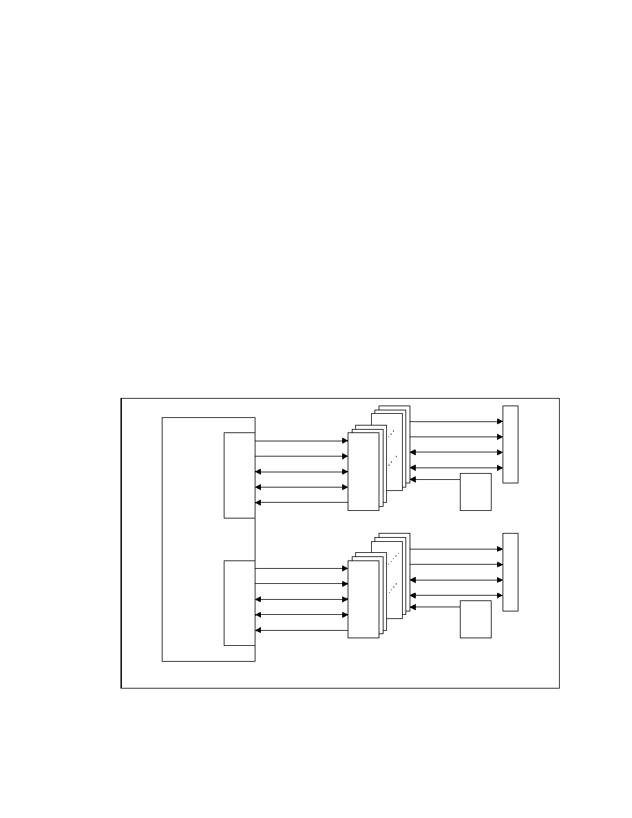
132
Datasheet
5.3. RDRAM
Interface
The 82840 MCH directly supports Dual channels(interfaces) of Rambus* Direct memory operating in
lock-step using RSL technology. The MCH support two different operation modes:
∑ Single Channel-pair Mode. The MCH is configured to directly support RDRAM devices on its
dual Rambus* interfaces. There is no MRH-R used on the memory subsystem. A maximum of
64 RDRAM devices are supported on the paired channels without external logic.
∑ Multiple Channel-pair Mode. The MCH is configured to use MRH-R on the memory subsystem.
Each Rambus* channel of the MRH-R on the MCH Direct Rambus* Interface A is paired with one
Rambus* channel of the MRH-R on the Direct Rambus* Interface B. The MCH supports one
MRH-R per interface and each MRH-R can support up to 2 RDRAM channels. Therefore, up to 4
RDRAM channels are supported by the MCH with a total of 2 MRH-Rs (1 MRH-R per interface).
The interface between the MCH and Direct RDRAM devices is referred to either as a "channel" or as an
"expansion channel." The channel interface consists of 33 signals including clocks (30 are RSL signals
and 3 are CMOS signals). When MRH-R is used for channel expansion, there are two additional RSL
signals per channel.
Figure 6 shows the interconnections between MCH and its dual Direct RDRAM channels configured in
single channel-pair mode.
Figure 6. Single Channel-pair Mode
82840 MCH
Channel A
RDRAM
CFM, CFM#
RQ[7:0]
DQ[15:0], DQP[1:0]
SFM, STM, SCFM
CTM, CTM#
Terminator
CFM, CFM#
RQ[7:0]
DQ[15:0], DQP[1:0]
SFM, STM, SCFM
Gen
Clock
Channel B
RDRAM
CFM, CFM#
RQ[7:0]
DQ[15:0], DQP[1:0]
SFM, STM, SCFM
CTM, CTM#
Terminator
CFM, CFM#
RQ[7:0]
DQ[15:0], DQP[1:0]
SFM, STM, SCFM
Gen
Clock
single_pr-ch

82840
MCH
R
Datasheet 133
Figure 7 shows the interconnections between MCH and its dual Direct RDRAM channels configured at
multiple channel-pair mode.
Figure 7. Multiple Channel-pair Mode
multi_pr-ch
Terminator
Rambus Expansion
Channel B
MRH-R
82840
MCH
Up to 32 RDRAM
Devices
Terminator
Rambus Expansion
Channel A
MRH-R
The maximum system memory supported by MCH depends on the Direct RDRAM device technology
(Table 14).
Table 14. Maximum Memory Supported For Various Configurations
Directly Supported
Supported via MRH-R(s)
RDRAM
Increments Maximum Increments Maximum
64Mb
16 MB
512 MB
16 MB
1 GB
128Mb
32 MB
1 GB
32 MB
2 GB
256Mb
6 4MB
2 GB
64 MB
4 GB
The row, column, and bank address bits required for the Direct RDRAM device depends on the number
of banks and page size of device. Table 15 shows the different combinations supported by the MCH.

134
Datasheet
Table 15. Direct RDRAM Device Configurations
CF# Device
Tech
Device
Capacity
in MB
# of Banks
(D= dependent)
Page
Size
# of Bank
Address
Bits
# of Row
Address
Bits
# of
Column
Address
Bits
1 64Mbit
8
16
(D)
1
KB
4
9
6
2 128Mbit 16
2x16
(D)
1
KB
5
9
6
3 32
2x16
(D)
1
KB
5
10
6
4
256Mbit
32 2x16
(D)
2
KB
4 10 7
A brief overview of the registers that configure the Direct RDRAM interface is provided below:
∑ Group Boundary Address Register (GBA). GBA registers define the upper and lower addresses
for a group of Direct RDRAM device pairs in a channel-pair. Each group requires a separate GBA
register. Each group consists of 4 device-pairs in single channel mode and 8 device-pairs in multiple
channel mode. The MCH contains 16 GBA registers.
∑ Group Architecture Register (GAR). GAR registers specify the architecture features of each
group of device pairs in a channel pair. The architecture features specified are bank type and device
core technology. Each GAR represents a group consisting of 4 device-pairs in single channel mode
and 8 device-pairs in multiple channel mode. There is a 1:1 correspondence between GBA and
GAR registers.
∑ RDRAM Timing Register (RDTR). The DTR defines the timing parameters for all devices in all
channels. The BIOS programs this register with "least common denominator" values after reading
configuration registers of each device in the channels.
∑ RDRAM Pool Sizing Register (RPMR). This register provides bits to program the number of
RDRAM device-pair in one of three RDRAM power management states.
∑ RDRAM Initialization Control Register (RICM). This register provides bits to program MCH to
do initialization activities on Direct RDRAM devices.
5.3.1.
RDRAM Organization and Configuration
The MCH supports 16/18-bit Direct RDRAM configurations. The MCH supports a maximum of
64 RDRAM devices (32 devices per channel) on its dual Direct RDRAM channels. Direct RDRAM
channel can be populated with a mix of 64Mbit, 128Mbit, and 256Mbit Direct RDRAM devices.

82840
MCH
R
Datasheet 135
5.3.1.1.
Rules for Populating RDRAM Devices
MCH Rambus* channels can be implemented such that it is fully or partially loaded with RDRAM
devices; however, they must be populated in either single-device pair or multiple-device pair.
∑ Single Device-pair. The 82840 MCH is configured to directly support RDRAM devices on its dual
Rambus* channel. Each RDRAM device of the MCH Direct Rambus* Interface A is paired with
one RDRAM device of the Direct Rambus* Interface B. There is no MRH-R used on the memory
subsystem.
∑ Multiple Device-pair. The 82840 MCH is configured to use MRH-R on the memory subsystem.
Each RDRAM deivce on Direct Rambus* Interface A is paired with one RDRAM device on the
Direct Rambus* Interface B.
From the MCH point-of-view, all device-pairs in the channels are grouped into logical groups. System
initialization software partitions the RDRAMs into groups of four device-pairs in single channel mode
operation and into groups of eight device-pairs in multiple channel mode operation. As a result, there can
be a maximum of 8 groups per channel-pair in single channel-pair operation and a maximum of 4 groups
per channel pair in multiple channel-pair mode. All device-pairs populated in a group must be of the
same architecture. That is, all device-pairs in a group must be the same core technology, and have the
same number of banks. Following are the rules for populating the groups:
∑ A group can be partially populated.
∑ There is no requirement that group members have to be populated in contiguous physical slots.
∑ There can be a maximum of 8 groups in single channel-pair mode or 4 groups per channel in
multiple channel-pair mode. A member that does not belong to any of the groups in the channel will
not be recognized.
The following table provides the device IDs for members in all groups.
Table 16. RDRAM Device Grouping
Single Channel Mode
Multiple Channel Mode
Device-Pair IDs for
Group Members
Group Name
Device Pair IDs for Group
Members
Group Name
0, 1, 2, 3
Group#0
0, 1, 2, 3, 4, 5, 6, 7,
Ch#0 Pair, Group#0
4, 5, 6, 7
Group#1
8, 9, 10, 11, 12, 13, 14, 15
Ch#0 Pair, Group#1
8, 9, 10, 11
Group#2
16, 17, 18, 19, 20, 21, 22, 23
Ch#0 Pair, Group#2
12, 13, 14, 15
Group#3
24, 25, 26, 27, 28, 28, 30, 31
Ch#0 Pair, Group#3
16, 17, 18, 19
Group#4
0, 1, 2, 3, 4, 5, 6, 7,
Ch#1 Pair, Group#0
20, 21, 22, 23
Group#5
8, 9, 10, 11, 12, 13, 14, 15
Ch#1 Pair, Group#1
24, 25, 26, 27
Group#6
16, 17, 18, 19, 20, 21, 22, 23
Ch#1 Pair, Group#2
28, 29, 30, 31
Group#7
24, 25, 26, 27, 28, 28, 30, 31
Ch#1 Pair, Group#3
0, 1, 2, 3, 4, 5, 6, 7,
Ch#2 Pair, Group#0
8, 9, 10, 11, 12, 13, 14, 15
Ch#2 Pair, Group#1
16, 17, 18, 19, 20, 21, 22, 23
Ch#2 Pair, Group#2
24, 25, 26, 27, 28, 28, 30, 31
Ch#2 Pair, Group#3

136
Datasheet
Single Channel Mode
Multiple Channel Mode
Device-Pair IDs for
Group Members
Group Name
Device Pair IDs for Group
Members
Group Name
0, 1, 2, 3, 4, 5, 6, 7,
Ch#3 Pair, Group#0
8, 9, 10, 11, 12, 13, 14, 15
Ch#3 Pair, Group#1
16, 17, 18, 19, 20, 21, 22, 23
Ch#3 Pair, Group#2
24, 25, 26, 27, 28, 28, 30, 31
Ch#3 Pair, Group#3
NOTES:
1. All RSL signals must be terminated at the far end from the MCH.
2. The default device ID for an RDRAM device after power up is 1Fh.
5.3.1.2.
RDRAM CMOS Signal Description and Usage
There are 3 CMOS signal pins per channel on the MCH to support Direct RDRAM device configuration,
SIO reset, register accesses, and Nap and PowerDown exits. These signals are SCK, CMD and SIO.
They are used to perform the following operations:
∑ SIO pin initialization
∑ SIO operations (includes register accesses and device reset)
∑ Device selection for Nap and PowerDown exits
Figure 8. RDRAM Devices Sideband CMOS Signal Configuration on Rambus* Channel A
rdram_cmos
SIO
SIO1
SIO0
SIO0
SCK
CMD
SCK
CMD
82840
MCH
Rambus channel
A
Note: MCH supports Dual Rambus Direct Channels.
RDRAM
RDRAM
RDRAM
RDRAM

82840
MCH
R
Datasheet 137
Figure 9. MRH-R Sideband CMOS Signal Configuration on Rambus* Channel A
rdram_cmos_mrh-r
SIO
SIO0
SCK
CMD
SCK
CMD
82840
MCH
Rambus channel
A
MRH-R
Table 17. Sideband CMOS Signal Description
Signal Description
SCK
Serial Clock: This signal serves as the clock for SIO and CMD signals. SCK is a clock source used
for reading from and writing to control register.
∑
For SIO operations and pin initialization, SCK
1 MHz
∑
For power mode operations, SCK
100 MHz
CMD
Command: CMD is a control signal used for power mode transitions, SIO pin configuration during
initialization, and framing of SIO operations. CMD is active high. This signal is sampled at both
edges of SCK and is a level sensitive signal.
SIO
Serial In Out: This bi-directional signal is daisy chained through all Direct RDRAM (SIO0 to SIO1)
devices in a channel. This pin carries data used for SIO operations that include register accesses,
device reset, and device ID initialization. SIO is also used for power mode control. SIO is an active
low signal and is sampled on the falling edge of SCK.
Table 18. CMD Signal Value Decode
SIO = 0, CMD Sample Value
on 4 SCK Edges
SIO = 1, CMD Sample Value
on 4 SCK Edges
Cycle 0
Cycle 1
Command
Cycle 0
Cycle 1
Command
0 1 x x
Nap
Exit
0 1 x x
Power-down
Exit
1 0 x x
Reserved
1 0 x x
Reserved
0 0 x x
No-op
0 0 x x
No-op
1 1 1 1
SIO
Request
Frame 1 1 1 1
SIO
Request
Frame
1 1 0 0
SIO
Reset
1 1 0 0
SIO
Reset
1 1 1 0
Reserved
1 1 1 0
Reserved
1 1 0 1
Reserved
1 1 0 1
Reserved

138
Datasheet
SIO Pin Initialization
SIO0 and SIO1 pins on Direct RDRAM devices are bi-directional; their direction needs to be initialized.
The "SIO Reset" initializes SIO0 and SIO1 pins on all Direct RDRAMs as daisy chain configuration and
is performed with SCK and CMD. Once the SIO daisy chain is fully configured, SIO operations can
occur. Note "SIO Reset" does NOT reset the entire device. For a complete description of operation and
associated timing diagram, refer to Direct RDRAM data sheet from Rambus*.
SIO Operations
SIO operations are also known as Direct RDRAM initialization operations. These operations include
Direct RDRAM register accesses and device reset, and are performed using the SCK, CMD, SIO0, and
SIO1 CMOS pins. For a complete description of operation and associated timing diagram, refer to the
Direct RDRAM data sheet from Rambus*.
Nap and PowerDown Exits
The Nap and Power Down exits are performed using CMD, SIO and SCK signals. For a complete
description and timing diagrams associated with Nap and PowerDown exits, refer to Direct RDRAM
data sheet from Rambus*.
5.3.1.3.
Direct RDRAM Core Refresh
All rows in an Direct RDRAM device must be refreshed within 32 ms. The refresh rate depends on the
device size and page size of a device. MCH supports two core refresh mechanisms: Active refresh and
self refresh.
∑ Active Refresh. Refresh and precharge after refresh commands are issued from the primary control
packet. These commands provide refresh support in Standby/Active modes.
∑ Self Refresh. Internal timebase and row/bank address counters in the core provide allow for a self
refresh in PowerDown modes without controller support.
5.3.1.4.
Direct RDRAM Current Calibration
All Direct RDRAM devices must be current calibrated once every 100 ms. There are RSL commands to
perform this function. The MCH schedules periodic current calibration activity such that every device in
the channel is current calibrated at least once every 100 ms.
5.3.2.
Direct RDRAM Command Encoding
The operations on a Direct RDRAM channel are performed using control packets. There are two types of
command packets--row(ROWA/ROWR) packet and column (COLC/COLM/COLX) packet. Each
command packet requires 4 Direct RDRAM clock duration and packet data is transferred on both
(leading and falling) edges of the clock. A Row packet contains 24 bits and column packet contains 40
bits.

82840
MCH
R
Datasheet 139
5.3.2.1.
Row Packet (ROWA/ROWR)
The row packet is defined using three RSL signals RQ[7:5]/ROW[2:0]. The row packet is generally the
first control packet issued to a device. Major characteristics of a row packet are:
∑ The only way to activate (sense) a row within a bank
∑ Independent of Direct RDRAM's active/standby state
∑ A non-broadcast row package causes an addressed Direct RDRAM to move to active state
The packet definition of row packet is provided in the following table.
Table 19. ROWA Packet for Activating (sensing) a Row (i.e., AV = 1)
Row #
Cycle 0
Cycle 1
Cycle 2
Cycle 3
ROW2
DR4T
DR[2]
BR[0]
BR[3]
R[10] R[8] R[5] R[2]
ROW1
DR4F
D[R1]
BR[1]
BR[4]
R[9] R[7] R[4] R[1]
ROW0
DR[3]
DR[0]
BR[2]
REV
AV
=
1
R[6] R[3] R[0]
Table 20. ROWR Packet for other operations (i.e., AV = 0)
Row #
Cycle 0
Cycle 1
Cycle 2
Cycle 3
ROW2 DR4T DR[2] BR[0] BR[3] ROP[10] ROP[8] ROP[5] ROP[2]
ROW1 DR4F DR[1] BR[1] BR[4] ROP[9] ROP[7] ROP[4] ROP[1]
ROW0
DR[3] DR[0] BR[2] REV AV
=
0
ROP[6]
ROP[3]
ROP[0]
DR4T DR4F
Device
ID
0 0
No
row
packet
0
1
DR[3:0], DR[4] = 0
1
0
DR[3:0], DR[4] = 1
1 1
Broadcast
DR[4] ≠ DR[0]
Device address
BR[5] ≠ BR[0]
Bank Address
R[10] ≠ R[0]
Row address
AV
Select between ROWA and ROWR, Active Row
ROP[10] ≠ ROP[0]
Opcode for Primary Control Packet
REV Reserved

140
Datasheet
Opcode bits
AV
10 9 8 7 6 5 4 3
2:
0
Operation
Description
1 x x x x x x x x xxx
Activate
Row
0 1 1 0 0 0 0 0 0 000
Precharge
0 1 1 0 0 0 0 0 1 000
Precharge
&
Relax
0 0 0 0 1 1 0 0 0 000
Refresh
0 1 0 1 0 1 0 0 0 000
Precharge
Postrefresh
0 0 0 0 0 0 1 0 0 000
Nap
0 0 0 0 0 0 1 1 0 000
Conditional
Nap
0 0 0 0 0 0 0 1 0 000
Power
Down
0 0 0 0 0 0 0 0 1 000
Relax
0 0 0 0 0 0 0 0 0 010
Temp
Calibration
Enable
0 0 0 0 0 0 0 0 0 001
Temp
Calibration
0 0 0 0 0 0 0 0 0 000
No-op
Legend:
x = Controller drives 0 or 1
0 = Controller drives 0
1 = Controller drives 1

82840
MCH
R
Datasheet 141
5.3.2.2.
Column Packet (COLC/COLX)
The column packet is defined using five of the RSL signals RQ[4:0]/COL[4:0]. Major characteristics of
column are:
∑ the only way to dispatch column operation for read or write
∑ requires the target Direct RDRAM to be in active state
Note: When an Direct RDRAM is in active state, it can receive both row and column packets. When a Direct
RDRAM is in Standby state, it can only receive a row packet. Thus, before sending a column packet,
make sure the addressed Direct RDRAM is in active state.
The packet definition of column packet is provided below.
Table 21. COLC Packet
Col #
Cycle 0
Cycle 1
Cycle 2
Cycle 3
COL4
DC[4]
S
=
1
C[6]
C[4]
COL3
DC[3]
C[5]
C[3]
COL2
DC[2]
COP[1]
REV
BC[2]
C[2]
COL1
DC[1]
COP[0]
BC[4]
BC[1]
C[1]
COL0
DC[0]
COP[2]
COP[3]
BC[3] BC[0] C[0]
DC[4:0]
Device ID for Column Operation
S
Start bit, for framing
M
Mask bit. Asserted indicates mask format for packet
COP[3:0]
Column Operation Code
C[6:0]
Address for Column operation
BC[4:0]
Bank Address for Column operation
REV Reserved
Table 22. COLC Packet Field Encodings
S
COP[3] COP[2] COP[1] COP[0]
Command
Operation
0 x x x x
No
operation
1
x
0
0
0
NOCOP. Retire write buffer of this device
1 x 0 0 1
Write
1 x 0 1 1
Read
NOTES:
All other combination are reserved

142
Datasheet
Table 23. COLX Packet (M = 0)
Cycle 0
Cycle 1
Cycle 2
Cycle 3
COL4
DX[4]
XOP[4]
REV
BX[1]
COL3
M = 0
DX[3]
XOP[3]
BX[4]
BX[0]
COL2
DX[2]
XOP[2]
BX[3]
COL1
DX[1]
XOP[1]
BX[2]
COL0
DX[0]
XOP[0]
DX[4:0]
Device ID for Extra operation
BX[4:0]
Bank Address for Extra operation
MA[7:0]
Byte Mask (low order)
MB[7:0]
Byte Mask (high order)
XOP[4:0]
Opcode for Extra Operation
REV Reserved
Table 24. COLM Packet and COLX Packet Field Encodings
M XOP
Bits
Operation
Description
4 3 2 1 0
1 x x x x x Non
existent
Xop
0 0 0 0 0 0 NoXop
0 1 0 0 0 0 Reserved
0 0 1 0 0 0 Calibrate
Current
0
0
1
1
0
0
Calibrate Current & Sample
0 0 0 0 0 1 Reserved
Legend: x = Controller drives 0 or 1
0 = Controller drives 0
1 = Controller drives 1
5.3.2.3. Data
Packet
Table 25. Data Packet
Cycle
0 Cycle
1 Cycle
2 Cycle
3
DQA[8:0] DA0[8:0] DA1[8:0] DA2[8:0] DA3[8:0] DA4[8:0] DA5[8:0] DA6[8:0] DA7[8:0]
DQB[8:0] DB0[8:0] DB1[8:0] DB2[8:0] DB3[8:0] DB4[8:0] DB5[8:0] DB6[8:0] DB7[8:0]

82840
MCH
R
Datasheet 143
5.3.3.
Direct RDRAM Register Programming
Software can read and write Direct RDRAM device registers by programming the RDRAM Initialization
Control Management (RICM) Register in the MCH. The register data returned by the device will be
available in the Device Register Data (DRD) Register.
5.3.4.
Direct RDRAM Operating States
The Direct RDRAM devices support different operating and idle states to minimize the power
consumption and thermal overload. Table 26 provides an overview of the different operating/power
states supported by Direct RDRAMs.
Table 26. DRAM Operating States
Direct RDRAM
State
Functionality Refresh
Scheme
RDRAM
Clock State
Inactive States
PowerDown
No operation allowed except refresh. Direct RDRAM
awaits CMOS signals to exit PowerDown state
Self Refresh
stopped
Nap
No operation allowed except refresh. Direct RDRAM
awaits Nap exit command to exit Nap
Active Refresh
stopped
Active States
Standby
Device Ready to receive row packet . with fast clock
Active Refresh
full speed
Active
Device ready to receive any control packet
Active Refresh
full speed
Active-Read
Device ready to receive any control packet.
Transmitting data on channel
Active Refresh
full speed
Active-Write
Device ready to receive any control packet.
Receiving data from channel
Active Refresh
full speed
Active-Read/Write state
A Direct RDRAM device is in active-Read/Write state when it is transferring data. This state lasts as
long as the data transfer is occurring. Once the data transfer is done, the Direct RDRAM transitions into
Active or Standby state based on the column command last executed.
Active State
A Direct RDRAM enters into active state immediately after the data transfer from/to that device is done
and the last COLC command that caused the data transfer does not have its RC bit set to 1. When a
device is in Active state, it can accept both row and column packets.
Standby State
A Direct RDRAM enters into Standby state either from Active-Read/Write or Active state. Transition
from Active-Read/Write to Standby happens if the last column executed has its RC bit set to 1.
Transition from Active to Standby happens if COLC or row specifies an operation with Relax. When a

144
Datasheet
device is in Standby mode, it can accept only row packets. Once a device receives any row packet, it
transitions into active state and then can accept a column packet.
Nap State
A Direct RDRAM enters into Nap state when it receives a row packet that specified an operation with
Nap. No operations except refresh is allowed during Nap state.
PowerDown State
A Direct RDRAM enters into PowerDown state when it receives a row packet which specified an
operation with PowerDown. No operations, except Self-refresh, are allowed during PowerDown state.
RDRAM Operating Pools
To minimize the operating power, the RDRAM devices are grouped into two operating pools called Pool
"A" and Pool "B".
Pool "A" and Pool "B" Operation
In the "pool" mode, two queues are used inside the MCH: pool "A" contains references to device pairs
that are currently in the active mode while pool "B" contains references to device pairs that are in the
standby mode. All devices that are found in neither pool are either napping or standby. Pool "A" may
hold between 1 and 8 device pairs, while pool "B" may be configured to contain between 1 and 16
device pairs.
5.3.5.
RDRAM Power Management
82840 MCH systems support ACPI based power management. The MCH puts all RDRAM devices into
PowerDown (PD) state during S3 power management states. To enter the PowerDown state all RDRAM
devices in the channel must be in active or standby state. The MCH then sends a broadcast PowerDown
command to that channel.
During PowerDown state, RDRAM devices are put into Self Refresh mode so that external (active)
refreshes are not required. During the powerdown state, the clocks to RDRAM are shut off. Exiting the
powerdown and Nap states are done through CMOS signals. Table 27 shows the actions taken by MCH
during different processor and System power states.
Table 27. RDRAM Power Management States
Processor
State
System
State
State of
RDRAMs in
Pool "A"
State of
RDRAMs in
Pool "B"
State of
RDRAMs in
Pool "C"
Refresh
Scheme
RDRAM
Clock
State
C0, C1, C2
(processor in
working state)
S0 Active-
Read/Write,
Active
Standby
Nap or
Standby
Active Running
(processor in
inactive state)
S1,
S3( STR)
No devices
in Pool "A"
No devices in
Pool "B"
Powerdown Self Stopped

82840
MCH
R
Datasheet 145
5.3.6. Data
Integrity
The MCH supports an Error Correcting Code (or Error Checking and Correcting) on the main memory
interface. The MCH can optionally be configured to generate the ECC code for writes to memory and
check the code for reads from memory. The MCH generates an 8-bit code word for each 64-bit QWord
of memory. Since the code word covers a full QWord, writes of less than a QWord require a read-merge-
write operation. Consider a DWord write to memory. In this case, when in ECC mode, the MCH will
read the QWord where the addressed DWord will be written, merge in the new DWord, generate a code
covering the new QWord and finally write the entire QWord and code back to memory. Any correctable
(single) errors detected during the initial QWord read are corrected before merging the new DWord.
Error scrubbing is supported by the MCH. When enabled, this feature not only corrects single bit error
data being returned to the requesting agent but also writes the corrected value back to the DRAM array.
Single-bit and multiple-bit errors set separate flags in the ERRSTS register. Single-bit errors and
mutiple-bit errors can be independently enabled to generate hub interface SERR, SMI, or SCI special
cycles to the ICH. The address and syndrome of the first single bit error are latched in the EAP and
DERRCTL registers. Subsequent single bit errors do not overwrite the EAP and DERRCTL registers
unless the single-bit error status bit is cleared. A multiple-bit error overwrites the EAP and DERRCTL
registers. Subsequent multiple-bit errors do not overwrite the EAP and DERRCTL registers, unless the
multiple-bit error status bit is cleared.
5.3.7.
RDRAM Array Thermal Management
The RDRAM thermal and power management functions of the 82840 MCH have been optimized for
workstation and server system designs. It is assumed that proper system design will always provide and
ensure adequate cooling in a 82840 chipset based system. The failsafe mechanism that protects the
devices in the event of a catastrophic failure requires an external thermal sensor. When the thermal
sensor is activated, the MCH immediately exits the "all devices on" mode and reverts the pool mode that
has been programmed by system software.
In a 82840-based system, RDRAM operates in one of three modes: active, standby, or nap. The number
of devices allowed in each state at any given time is dictated by the heat dissipation budget specified by
the system designer. From 1 to 8 device-pairs may be in pool "A" and are configured to operate in the
active mode. In addition, from 1 to 16 device-pairs may be in pool "B" and are configured to operate in
the standby mode. The rest of the device-pairs are in pool "C" and may be configured to operate in
either nap mode or standby mode. Regardless of how many devices are configured into pool "A" and
pool "B" or whether the pool "C" devices are in napping or standby mode, the system designer is
responsible for providing adequate cooling for the number of RDRAM devices in the system.
After BIOS loads the system's "target" values into the DPS register and initializes the pools, it should
load a "safer" set of values into the DPS register without setting the POOLINIT field. The POOLINIT
bit instructs the MCH to transition to the new pool sizes. There are two other conditions that cause the
82840 MCH to resize and initialize the pools:
∑ The transition of the OVERT# pin from electrical 1 to electrical 0
∑ The detection of an overtemperature condition on any RDRAM device
The OVERT# method is intended to allow system designers to use external thermal sensors to monitors
the system temperature and assert OVERT# when system temperature exceeds system specifications.
When the 82840 MCH detects a falling edge on the OVERT# signal, it reinitializes and resizes the pools
with whatever values are in the DPS register. Also, the RDRAM devices report overtemperature

146
Datasheet
conditions back to the MCH via a special bit asserted during their current calibration operations. When
the MCH detects an overtemperature condition in any of the memory devices, the RDRAM pools are
reinitialized with "safer" values. Finally, the MCH may be configured to send an SERR, SCI, or SMI hub
interface message to ICH. The software may take action to cool the system or to log the condition.
5.4.
System Reset
The reset scheme for 82840 MCH is shown in Figure 10. After PWROK is asserted to indicate the
system power is stable, RSTIN# is generated by ICH and is used as an input to reset the MCH. The MCH
always asserts CPURST#, if RSTIN# is asserted. The assertion of CPURST# resets the processors, as
well as ITP. CPURST# is deasserted synchronous to the host bus clock.
Figure 10. 82840 MCH Reset
reset_overview
ITP
MCH
CPURST#
RSTIN#
ICH
PCIRST#
INIT#
PWROK
PWRGOOD
ITP_RST#
INIT#
Processor
RESET#
PWRGOOD
NOTES:
The diagram does not represent all the details for schematics connection.

82840
MCH
R
Datasheet 147
6.
Ballout and Package Information
6.1.
MCH Ball List
The following two figures show a fooprint of the MCH ballout with the signals indicated for each ball
location. Table 28 provides an alphabetical ball list.

148
Datasheet
Figure 11. MCH Ballout (Top View, Left Side)
1 2 3 4 5 6 7 8 9 10 11 12 13
A
AGPRCOMP AGPREF
GAD8
VCC1_8
CLK66 GFRAME# GAD17
GC/BE3#
GAD25
GAD30
SBA4
SBA2
RBF#
B
GAD3 GAD7 GC/BE0# GAD12 VSS GDEVSEL# VSS GAD21 GAD24 VSS
SBA5
VSS
PIPE#
C
GAD2 GAD6 VDDQ VSS GPAR GTRDY# GAD18 VDDQ ADSTB1 GAD29 SBSTB# SBA3 VDDQ
D
GAD1
VSS
ADSTB0 GAD11 G/CBE1# GSTOP# GC/BE2# GAD22 ADSTB1# GAD28
SBA6
SBSTB WBF#
E
GAD0 GAD5
ADSTB0#
GAD10
GAD15 VSS GAD16
GAD19 VSS GAD27 SBA7 VSS SBA0
F
VSS GAD4 VSS GAD9 GAD14 GSERR#
GIRDY# GAD20 GAD23 GAD26 GAD31 VDDQ SBA1
G
CHA_DQA8
VSS
CHA_DQA7
VSS GAD13 VDDQ VDDQ VDDQ VDDQ Vcc1_8
H
CHA_DQA6 VSS CHA_DQA5 VSS
VSS
VDDQ Vcc1_8
J
CHA_DQA2 CHA_DQA4 CHA_DQA3
VSS
VSS
VCC1_8
VCC1_8
K
CHA_DQA0 VSS CHA_DQA1 VSS
VSS VCC1_8 VCC1_8
L
CHA_CFM CHA_CFM#
VSS
VSS
VSS
VCC1_8
VCC1_8 VCC1_8 VSS
M
CHA_CTM# CHA_CTM
VSS
VSS
VSS
VCC1_8
VCC1_8 VSS VSS
N
CHA_RQ6 VSS CHA_RQ7 VSS
VSS CHA_REF0
VSS VSS VSS
P
CHA_RQ5
CHA_EXP1
CHA_EXP0 VSS
VSS CHA_REF1
VSS VSS VSS
R
CHA_RQ4 VSS CHA_RQ3 VSS
VSS Vcc1_8
VCC1_8 VSS VSS
T
CHA_RQ2 CHA_RQ1 CHA_RQ0
VSS
VSS
VCC1_8
VCC1_8 VCC1_8 VSS
U
CHA_DQB1 VSS CHA_DQB0 VSS
VSS VCC1_8 VCC1_8
V
CHA_DQB3 CHA_DQB6 CHA_DQB2
VSS
VSS
VCC1_8
VCC1_8
W
CHA_DQB5 VSS CHA_DQB4 VSS
VSS
NC
VCC1_8
Y
CHA_DQB7 VSS CHA_DQB8 VSS
VSS Vcc1_8 Vcc1_8 VCC1_8 VCC1_8 VCC1_8
AA
VSS
VSS
VSS
CMDA SCKA OVERT# Vcc1_8 VCC1_8 VCC1_8 VCC1_8 VCC1_8 VCC1_8
CHB_REF0
AB
RCLKOUTA
SIOA
DCLKOUTA
HLAPD0
VSS
RSTIN#
VSS VSS VSS VSS VSS VSS VSS
AC
HLAPD3
VSS HLA11
HLAPD2
HLAPD1
TEST#
VSS VSS VSS VSS VSS VSS VSS
AD
HLA8
HLASTB# HLASTB
VSS
DCLKOUTB
VSS
CHB_DQA7 CHB_DQA5 CHB_DQA3 CHB_DQA1
VSS
VSS
CHB_RQ7
AE
HLAPD6 VSS
HLA10 HLAPD4 HLA9
VSS
VSS
VSS CHB_DQA4 VSS CHB_CFM#
CHB_CTM VSS
AF
HLAPD7
HLAPD5
HLAREF HLAZCOMP RCLKOUTB
VSS
CHB_DQA8 CHB_DQA6 CHB_DQA2 CHB_DQA0 CHB_CFM CHB_CTM# CHB_RQ6
1 2 3 4 5 6 7 8 9 10 11 12 13

82840
MCH
R
Datasheet 149
Figure 12. MCH Ballout (Top View, Right Side)
14 15 16 17 18 19 20 21 22 23 24 25 26
GREQ# HLBSTB0# HLBSTB0 HLB17
HLBPD9 HLBRCOMP IERR# GTLREFA VCC1_8
VSS
DEP2#
DEP4#
DEP0#
A
GGNT# VSS HLBPD4 VSS HLBPD10 VSS HLBREF
DEP1# HCLKIN DEP3# DEP7# VSS DEP5#
B
ST0 HLBPD1
HLBPD5 HLB19
HLBPD11
HLBPD13
DEP6# HD61# VSS HD62# HD58# HD63# HD55#
C
ST1 HLBPD2
HLBPD6 HLB16
HLBSTB1#
HLBPD14
HD60# HD53# HD57# HD56# HD50# HD54# HD46#
D
ST2 VSS HLBPD7 VSS
HLBSTB1
VSS HD49# VSS HD51# HD59#
HD48# VSS HD42#
E
HLBPD0
HLBPD3 HLB18 HLBPD8
HLBPD12
HLBPD15
HD45# HD39# HD52# VSS HD41# HD47# HD43#
F
Vcc1_8 Vcc1_8 Vcc1_8 VSS HD37# HD33# HD44# HD36# HD40# HD35#
G
VTT HD31# VSS HD34#
HD38# VSS HD30#
H
VTT HD27# HD24# HD32# HD28# HD29#
HD23#
J
VTT HD21# HD16# HD26# HD25# HD22# HD13#
K
VSS VCC1_8
VCC1_8
HD11# VSS HD19#
HD18# VSS HD10#
L
VSS VSS
VCC1_8
HD14# HD9# HD20# HD17# HD15# HD8#
M
VSS VSS VSS
HD5# HD3# HD12# HD7# HD6# HD1#
N
VSS VSS VSS
BERR# VSS HD4# HD2# VSS HA33#
P
VSS VSS
VCC1_8
HA34# HA30# HD0# CPURST#
HA35# HA32#
R
VSS VCC1_8
VCC1_8
HA31# HA27# HA22# HA29# HA26# HA24#
T
VTT HA23# VSS HA19# HA28# VSS HA20#
U
VTT HA18# HA16# HA13# HA21# HA25# HA15#
V
VTT HA14# HA10# HA5# HA17# HA11# HA12#
W
VCC1_8
VCC1_8
VCC1_8
VSS HA9# VSS HA4# HA8# VSS HA7#
Y
CHB_REF1
Vcc1_8 VCC1_8 VCC1_8 VCC1_8 VCC1_8 VCC1_8 BNR# BPRI# HA3#
HA6# HREQ0# HTRDY#
AA
VSS VSS VSS VSS VSS VSS VSS SCKB
DEFER#
HREQ1#
HREQ4#
HLOCK#
HREQ2#
AB
VSS VSS VSS VSS VSS VSS VSS CMDB VSS
HREQ3#
DRDY#
VSS HITM#
AC
CHB_EXP0 CHB_RQ3 CHB_RQ0 CHB_DQB0 CHB_DQB2 CHB_DQB4 CHB_DQB8
VSS
DBSY#
RS0#
HIT#
RS2#
RP#
AD
CHB_EXP1 VSS CHB_RQ1 VSS CHB_DQB6 VSS
VSS
VSS
SIOB
VSS RSP# VSS ADS#
AE
CHB_RQ5 CHB_RQ4 CHB_RQ2 CHB_DQB1 CHB_DQB3 CHB_DQB5 CHB_DQB7
VSS
GTLREFB
RS1#
BREQ0#
AP0#
AP1#
AF
14 15 16 17 18 19 20 21 22 23 24 25 26

150
Datasheet
Table 28. MCH Alphabetical Ballout List
Signal Ball
#
ADS# AE26
ADSTB0 D3
ADSTB0# E3
ADSTB1 C9
ADSTB1# D9
AGPRCOMP A1
AGPREF A2
AP0# AF25
AP1# AF26
BERR# P21
BNR# AA21
BPRI# AA22
BREQ0# AF24
CHA_CFM L1
CHA_CFM# L2
CHA_CTM M2
CHA_CTM# M1
CHA_DQA0 K1
CHA_DQA1 K3
CHA_DQA2 J1
CHA_DQA3 J3
CHA_DQA4 J2
CHA_DQA5 H3
CHA_DQA6 H1
CHA_DQA7 G3
CHA_DQA8 G1
CHA_DQB0 U3
CHA_DQB1 U1
CHA_DQB2 V3
CHA_DQB3 V1
CHA_DQB4 W3
CHA_DQB5 W1
CHA_DQB6 V2
CHA_DQB7 Y1
CHA_DQB8 Y3
Signal Ball
#
CHA_EXP0 P3
CHA_EXP1 P2
CHA_REF0 N6
CHA_REF1 P6
CHA_RQ0 T3
CHA_RQ1 T2
CHA_RQ2 T1
CHA_RQ3 R3
CHA_RQ4 R1
CHA_RQ5 P1
CHA_RQ6 N1
CHA_RQ7 N3
CHB_CFM AF11
CHB_CFM# AE11
CHB_CTM AE12
CHB_CTM# AF12
CHB_DQA0 AF10
CHB_DQA1 AD10
CHB_DQA2 AF9
CHB_DQA3 AD9
CHB_DQA4 AE9
CHB_DQA5 AD8
CHB_DQA6 AF8
CHB_DQA7 AD7
CHB_DQA8 AF7
CHB_DQB0 AD17
CHB_DQB1 AF17
CHB_DQB2 AD18
CHB_DQB3 AF18
CHB_DQB4 AD19
CHB_DQB5 AF19
CHB_DQB6 AE18
CHB_DQB7 AF20
CHB_DQB8 AD20
CHB_EXP0 AD14
Signal Ball
#
CHB_EXP1 AE14
CHB_REF0 AA13
CHB_REF1 AA14
CHB_RQ0 AD16
CHB_RQ1 AE16
CHB_RQ2 AF16
CHB_RQ3 AD15
CHB_RQ4 AF15
CHB_RQ5 AF14
CHB_RQ6 AF13
CHB_RQ7 AD13
CLK66 A5
CMDA AA4
CMDB AC21
CPURST# R24
DBSY# AD22
DCLKOUTA AB3
DCLKOUTB AD5
DEFER# AB22
DEP0# A26
DEP1# B21
DEP2# A24
DEP3# B23
DEP4# A25
DEP5# B26
DEP6# C20
DEP7# B24
DRDY# AC24
G/CBE1# D5
GAD0 E1
GAD1 D1
GAD2 C1
GAD3 B1
GAD4 F2
GAD5 E2
Signal Ball
#
GAD6 C2
GAD7 B2
GAD8 A3
GAD9 F4
GAD10 E4
GAD11 D4
GAD12 B4
GAD13 G5
GAD14 F5
GAD15 E5
GAD16 E7
GAD17 A7
GAD18 C7
GAD19 E8
GAD20 F8
GAD21 B8
GAD22 D8
GAD23 F9
GAD24 B9
GAD25 A9
GAD26 F10
GAD27 E10
GAD28 D10
GAD29 C10
GAD30 A10
GAD31 F11
GC/BE0# B3
GC/BE2# D7
GC/BE3# A8
GDEVSEL# B6
GFRAME# A6
GGNT# B14
GIRDY# F7
GPAR C5
GREQ# A14

82840
MCH
R
Datasheet 151
Signal Ball
#
GSERR# F6
GSTOP# D6
GTLREFA A21
GTLREFB AF22
GTRDY# C6
HA3# AA23
HA4# Y23
HA5# W23
HA6# AA24
HA7# Y26
HA8# Y24
HA9# Y21
HA10# W22
HA11# W25
HA12# W26
HA13# V23
HA14# W21
HA15# V26
HA16# V22
HA17# W24
HA18# V21
HA19# U23
HA20# U26
HA21# V24
HA22# T23
HA23# U21
HA24# T26
HA25# V25
HA26# T25
HA27# T22
HA28# U24
HA29# T24
HA30# R22
HA31# T21
HA32# R26
HA33# P26
Signal Ball
#
HA34# R21
HA35# R25
HCLKIN B22
HD00# R23
HD1# N26
HD2# P24
HD3# N22
HD4# P23
HD5# N21
HD6# N25
HD7# N24
HD8# M26
HD9# M22
HD10# L26
HD11# L21
HD12# N23
HD13# K26
HD14# M21
HD15# M25
HD16# K22
HD17# M24
HD18# L24
HD19# L23
HD20# M23
HD21# K21
HD22# K25
HD23#
J26
HD24# J22
HD25# K24
HD26# K23
HD27# J21
HD28# J24
HD29# J25
HD30# H26
HD31# H21
HD32# J23
Signal Ball
#
HD33# G22
HD34# H23
HD35# G26
HD36# G24
HD37# G21
HD38# H24
HD39# F21
HD40# G25
HD41# F24
HD42# E26
HD43# F26
HD44# G23
HD45# F20
HD46# D26
HD47# F25
HD48# E24
HD49# E20
HD50# D24
HD51# E22
HD52# F22
HD53# D21
HD54# D25
HD55# C26
HD56# D23
HD57# D22
HD58# C24
HD59# E23
HD60# D20
HD61# C21
HD62# C23
HD63# C25
HIT# AD24
HITM# AC26
HLA8 AD1
HLA9 AE5
HLA10 AE3
Signal Ball
#
HLA11 AC3
HLAPD0 AB4
HLAPD1 AC5
HLAPD2 AC4
HLAPD3 AC1
HLAPD4 AE4
HLAPD5 AF2
HLAPD6 AE1
HLAPD7 AF1
HLAREF AF3
HLASTB AD3
HLASTB# AD2
HLAZCOMP AF4
HLB16 D17
HLB17 A17
HLB18 F16
HLB19 C17
HLBPD0 F14
HLBPD1 C15
HLBPD2 D15
HLBPD3 F15
HLBPD4 B16
HLBPD5 C16
HLBPD6 D16
HLBPD7 E16
HLBPD8 F17
HLBPD9 A18
HLBPD10 B18
HLBPD11 C18
HLBPD12 F18
HLBPD13 C19
HLBPD14 D19
HLBPD15 F19
HLBRCOMP A19
HLBREF B20
HLBSTB0 A16

152
Datasheet
Signal Ball
#
HLBSTB0# A15
HLBSTB1 E18
HLBSTB1# D18
HLOCK# AB25
HREQ0# AA25
HREQ1# AB23
HREQ2# AB26
HREQ3# AC23
HREQ4# AB24
HTRDY# AA26
IERR# A20
NC W6
OVERT# AA6
PIPE# B13
RBF# A13
RCLKOUTA AB1
RCLKOUTB AF5
RP# AD26
RS0# AD23
RS1# AF23
RS2# AD25
RSP# AE24
RSTIN# AB6
SBA0 E13
SBA1 F13
SBA2 A12
SBA3 C12
SBA4 A11
SBA5 B11
SBA6 D11
SBA7 E11
SBSTB D12
SBSTB# C11
SCKA AA5
SCKB AB21
SIOA AB2
Signal Ball
#
SIOB AE22
ST0 C14
ST1 D14
ST2 E14
TEST# AC6
VCC1_8 W7
VCC1_8 Y8
VCC1_8 Y19
VCC1_8 AA8
VCC1_8 AA19
VCC1_8 AA20
VCC1_8 G10
VCC1_8 G17
VCC1_8 G18
VCC1_8 G19
VCC1_8 H7
VCC1_8 L11
VCC1_8 L12
VCC1_8 L15
VCC1_8 L16
VCC1_8 M11
VCC1_8 M16
VCC1_8 R6
VCC1_8 R11
VCC1_8 R16
VCC1_8 T11
VCC1_8 T12
VCC1_8 T15
VCC1_8 T16
VCC1_8 Y6
VCC1_8 Y7
VCC1_8 AA7
VCC1_8 AA15
VCC1_8 A4
VCC1_8 A22
VCC1_8 J6
Signal Ball
#
VCC1_8 J7
VCC1_8 K6
VCC1_8 K7
VCC1_8 L6
VCC1_8 M6
VCC1_8 T6
VCC1_8 U6
VCC1_8 U7
VCC1_8 V6
VCC1_8 V7
VCC1_8 Y9
VCC1_8 Y10
VCC1_8 Y17
VCC1_8 Y18
VCC1_8 AA9
VCC1_8 AA10
VCC1_8 AA11
VCC1_8 AA12
VCC1_8 AA16
VCC1_8 AA17
VCC1_8 AA18
VDDQ C3
VDDQ C8
VDDQ C13
VDDQ F12
VDDQ G6
VDDQ G7
VDDQ G8
VDDQ G9
VDDQ H6
VSS A23
VSS B5
VSS B7
VSS B10
VSS B12
VSS B15
Signal Ball
#
VSS B17
VSS B19
VSS B25
VSS C4
VSS C22
VSS D2
VSS E6
VSS E9
VSS E12
VSS E15
VSS E17
VSS E19
VSS E21
VSS E25
VSS F1
VSS F3
VSS F23
VSS G2
VSS G4
VSS G20
VSS H2
VSS H4
VSS H5
VSS H22
VSS H25
VSS J4
VSS J5
VSS K2
VSS K4
VSS K5
VSS L3
VSS L4
VSS L5
VSS L13
VSS L14
VSS L22

82840
MCH
R
Datasheet 153
Signal Ball
#
VSS L25
VSS M3
VSS M4
VSS M5
VSS M12
VSS M13
VSS M14
VSS M15
VSS N2
VSS N4
VSS N5
VSS N11
VSS N12
VSS N13
VSS N14
VSS N15
VSS N16
VSS P4
VSS P5
VSS P11
VSS P12
VSS P13
VSS P14
VSS P15
VSS P16
VSS P22
VSS P25
VSS R2
VSS R4
VSS R5
VSS R12
VSS R13
VSS R14
VSS R15
VSS T4
VSS T5
Signal Ball
#
VSS T13
VSS T14
VSS U2
VSS U4
VSS U5
VSS U22
VSS U25
VSS V4
VSS V5
VSS W2
VSS W4
VSS W5
VSS Y2
VSS Y4
VSS Y5
VSS Y20
VSS Y22
VSS Y25
VSS AA1
VSS AA2
VSS AA3
VSS AB5
VSS AB7
VSS AB8
VSS AB9
VSS AB10
VSS AB11
VSS AB12
VSS AB13
VSS AB14
VSS AB15
VSS AB16
VSS AB17
VSS AB18
VSS AB19
VSS AB20
Signal Ball
#
VSS AC2
VSS AC7
VSS AC8
VSS AC9
VSS AC10
VSS AC11
VSS AC12
VSS AC13
VSS AC14
VSS AC15
VSS AC16
VSS AC17
VSS AC18
VSS AC19
VSS AC20
VSS AC22
VSS AC25
VSS AD4
VSS AD6
VSS AD11
VSS AD12
VSS AD21
VSS AE2
VSS AE6
VSS AE7
VSS AE8
VSS AE10
VSS AE13
VSS AE15
VSS AE17
VSS AE19
VSS AE20
VSS AE21
VSS AE23
VSS AE25
VSS AF6
Signal Ball
#
VSS AF21
VTT H20
VTT J20
VTT K20
VTT U20
VTT V20
VTT W20
WBF# D13

154
Datasheet
6.2. Package
Information
This specification outlines the mechanical dimensions for the 82840 MCH. The package is a 544 ball
grid array (BGA).
Figure 13. 82840 MCH BGA Package Dimensions (Top and Side Views)
Pin A1 I.D.
Pin A1 corner
D
D1
E
E1
Top View
A
A2
A1
c
Side View
pkgbga_top&side.vsd
Seating Plane
-C-
45į Chamfer
(4 places)
30į

82840
MCH
R
Datasheet 155
Figure 14. 82840 MCH BGA Package Dimensions (Bottom View)
pkgbga_544
Pin A1 corner
e
544 BGA
Bottom View
2
10
16
20
22
3
5
7
9
11
13
15
17
19
1
21
23
4
6
18
8
12
14
A
B
C
D
E
F
G
H
J
K
L
P
R
T
U
V
Y
AB
AA
AC
N
W
M
j
l
e
b
24
25
26
AD
AE
AF
Table 29. Package Dimensions
Symbol Min
Nominal
Max
Units Note
A 2.17
2.38
2.59 mm
A1 0.50
0.60
0.70
mm
A2 1.12
1.17
1.22
mm
D 34.80
35.00
35.20 mm
D1 29.75
30.00
30.25
mm
E 34.80
35.00
35.20 mm
E1 29.75
30.00
30.25
mm
e
1.27 (solder ball pitch)
mm
I 1.63
REF. mm
J 1.63
REF. mm
M
26 x 26 Matrix
mm
b
2
0.60
0.75
0.90 mm
c 0.55
0.61
0.67 mm
NOTES:
1. All dimensions and tolerances conform to ANSI Y14.5-1982
2. Dimension is measured at maximum solder ball diameter parallel to primary datum (-C-)
3. Primary Datum (-C-) and seating plane are defined by the spherical crowns of the solder balls.

156
Datasheet
6.2.1.
82840 RSL Nomalized Trace Length Data
Expansion Channel A
L
PKG
Normalized to CHA_DQA8
Expansion
Channel
B
L
PKG
Normalized to CHB_DQB7
Signal Ball
L
PKG
(mils)
Signal
Ball
L
PKG
(mils)
CHA_CFM L1 102.756
CHB_CFM AF11 103.543
CHA_ CFM#
L2
118.897
CHB_ CFM#
AE11
110.630
CHA_CTM M2 130.315
CHB_CTM AE12
109.842
CHA_CTM# M1 117.716
CHB_CTM# AF12
110.236
CHA_DQA0 K1
93.701
CHB_DQA0 AF10
101.968
CHA_ DQA1
K3
162.204
CHB_ DQA1
AD10
150.393
CHA_ DQA2
J1
40.551
CHB_ DQA2
AF9
81.102
CHA_ DQA3
J3
137.008
CHB_ DQA3
AD9
137.401
CHA_ DQA4
J2
87.795
CHB_ DQA4
AE9
115.354
CHA_ DQA5
H3
115.748
CHB_ DQA5
AD8
120.079
CHA_ DQA6
H1
61.811
CHB_ DQA6
AF8
48.425
CHA_ DQA7
G3
99.212
CHB_ DQA7
AD7
109.055
CHA_DQA8 G1
0.000
CHB_DQA8 AF7
29.921
CHA_DQB0 U3 143.307
CHB_DQB0 AD17
130.708
CHA_ DQB1
U1
122.441
CHB_ DQB1
AF17
72.441
CHA_ DQB2
V3
164.173
CHB_ DQB2
AD18
120.079
CHA_ DQB3
V1
111.417
CHB_ DQB3
AF18
69.291
CHA_ DQB4
W3
151.181
CHB_ DQB4
AD19
142.126
CHA_ DQB5
W1
68.504
CHB_ DQB5
AF19
34.252
CHA_ DQB6
V2
106.693
CHB_ DQB6
AE18
111.417
CHA_ DQB7
Y1
40.157
CHB_ DQB7
AF20
0.000
CHA_ DQB8
Y3
134.252
CHB_ DQB8
AD20
70.472
CHA_EXP0 P3 192.519
CHB_EXP0 AD14
160.236
CHA_EXP1 P2 129.921
CHB_EXP1 AE14
161.811
CHA_RQ0 T3 185.433
CHB_RQ0 AD16 152.362
CHA_ RQ1
T2
131.496
CHB_ RQ1
AE16
93.307
CHA_ RQ2
T1
126.378
CHB_ RQ2
AF16
98.425
CHA_ RQ3
R3
189.370
CHB_ RQ3
AD15
157.480
CHA_ RQ4
R1
85.039
CHB_ RQ4
AF15
106.693
CHA_ RQ5
P1
78.740
CHB_ RQ5
AF14
101.968
CHA_ RQ6
N1
124.409
CHB_ RQ6
AF13
112.205
CHA_ RQ7
N3
175.984
CHB_ RQ7
AD13
161.811

82840
MCH
R
Datasheet 157
These lengths must be considered when matching trace lengths as described in the Intel
ģ
840 Chipset
Design Guide. Note that these lengths are normalized to 0 with the longest trace on the package. They do
not represent the actual lengths from pad to ball. The following formula is used to determine
L
PCB
L
PCB
= (
L
pkg
*V
pkg
) / V
PCB
Where:
L
PCB
is the nominal
PCB trace length to be added on the PCB
L
Pkg
is the nominal
package trace length.
V
pkg
is the package trace velocity, and the nominal value is 180 ps/in
V
PCB
is the PCB trace velocity
The data given can be renormalized to start routing from a different ball. If a different RSL signal (other
than longest trace) is used for nominalization, simply use the following equation:
New
L
pkg
' =
L
pkg
-
L
RSL
For example: For the MCH, if MCH CHA_CFM trace length is used for nominalization, then:
Signal
L
PKG
(mils)
New
L
PKG
(mils)
CHA_CFM 102.756
0.000
CHA_CFM# 118.897
16.142
CHA_CTM 130.315
27.559
:
:
:
:
:
:
CHA_RQ6 124.409
21.653
CHA_RQ7 175.984
73.228

158
Datasheet
This page is intentionally left blank.

82840
MCH
R
Datasheet 159
7. Testability
In the MCH, the testability for Automated Test Equipment (ATE) board level testing has been changed
from traditional NAND chain to the new XOR chain. An XOR-Tree is a chain of XOR gates, each with
one Input pin connected to it as shown in Figure 15. The first XOR gate should have one pin connected
to VCC1_8.
Figure 15. XOR-Tree Chain
Input
XOR
Out
xor.vsd
Input
Input
Input
Input
VCC1_8
The algorithm used for in-circuit test is as follows:
∑ Drive "0" onto all Input pins. This, along with the first XOR gate having one input connected to
VCC1_8 and the Outputs being non-inverting, consistently produces a "1" at "XOR out", regardless
of how many XOR gates are in the chain.
∑ Drive each Input pin one at a time, first to a "1" and then back to a "0". This causes "XOR out" first
to produce a "0" and then a "1".
∑ The Output pins can now be checked by driving a "0" onto the Pin of the XOR gate that has its
second input to the XOR gate connected to GND and then back to a "1". The Output pins will go to
a "0" and then back to a "1".
The above algorithm is for all pins properly soldered to the board under test and no pins connected to a
power plane. If there is an even number of total signal pins connected to a power plane or unsoldered and
floating to a "1" logic level, then the following would happen:
∑ Drive "0" onto all other Input and Bi-directional pins. "XOR out" would start out at a "1" level
instead of a "0".
∑ Drive each Input or Bi-directional pin, one at a time, first to a "1" and then back to a "0." This
causes "XOR out" first to produce a "0" and then a "1".
A flexible test model used for in-circuit test will need to determine if "XOR out" initially is a "0" or "1"
level. One at a time, each Input or Bi-directional pin is driven to "1" and then back to a "0." The "XOR
out" will first toggle to the opposite state that was initially determined and then toggle back to the
initially determined state. Any unsoldered pin will cause "XOR out" not to toggle.
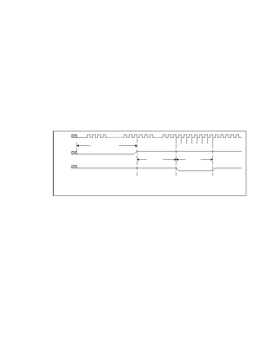
160
Datasheet
7.1. Initialization
Sequence
Two pins are used to enter the XOR chain test mode as shown in the Figure 16.
XOR Chain Test Mode Entering Rules:
∑ TEST# should be driven "Low" for exactly 7 clocks after "RSTIN#" goes "High" (inactive).
∑ Once TEST# is driven "Low" for exactly 7 clocks and then "High", it will "LOCK" in the XOR
chain test mode.
∑ TEST# should never be driven in the "Low" state other than driven "Low" for 7 clocks to enter the
XOR chain test mode. If TEST# goes "Low" for a moment because of a glitch, the MCH needs to
be "reset" for going to normal operation or entering the XOR chain test mode again.
Figure 16. XOR Chain Test Mode Initialization
CLK66
RSTIN#
any number of
clocks between
16 and 64
1 2 3 4
6
5
7
TEST#
minimum
10 clocks
Exactly 7
clocks
"Lock" in the
XOR Chain
Test Mode
To Enter The XOR Chain Test Mode, Drive TEST# LOW for
EXACTLY 7 CLK66 Clocks After RSTIN# Is High (inactive).
test_init

82840
MCH
R
Datasheet 161
7.2. XOR
Chains
Table 30. XOR Chain #0 Connections
Name Ball
Chain
Element #
Note
GC/BE1# D5 1
Input
GSERR# F6 2
GAD_15 E5 3
GC/BE0# B3 4
GAD_11 D4 5
GAD_14 F5 6
GAD_7 B2 7
GAD_10 E4 8
GAD_13 G5 9
GAD_6 C2 10
ADSTB0 D3 11
GAD_2 C1 12
GAD_5 E2 13
GAD_1 D1 14
GAD_4 F2 15
GAD_0 E1 16
GAD_9 F4 17
GAD_8 A3 18
GAD_12 B4 19
GAD_3 B1 20
CHA_SIO AB2 21
CHA_CMD AA4
22
CHA_SCK AA5 23
HCLKOUTA AB3
24
RCLKOUTA AB1
25
HLA11 AC3 26
HLA8 AD1 27
HLA3 AC1 28
HLA0 AB4 29
HLA6 AE1 30
HLA2 AC4 31
HLASTB AD3 32
HLASTB# AD2 33
HLA7 AF1 34
HLA1 AC5 35
HLA5 AF2 36
Table 30. XOR Chain #0 Connections
Name Ball
Chain
Element #
Note
HLA4 AE4 37
HLA10 AE3 38
HLAZCOMP AF4
39
HLA9 AE5 40
TEST# AC6 41
OVERT# AA6 42
HCLKOUTB AD5
43
RCLKOUTB AF5
44
Output
Table 31. XOR Chain #1 Connections
Name Ball
Chain
Element #
Note
ADSTB0# E3
1
Input
CHB_SCK AB21
2
CHB_CMD AC21
3
CHB_SIO AE22
4
RS1# AF23 5
DBSY# AD22 6
BREQ0# AF24 7
RSP# AE24 8
AP0# AF25 9
RS0# AD23 10
RP# AD26 11
ADS# AE26 12
HIT# AD24 13
HREQ3# AC23 14
RS2# AD25 15
DRDY# AC24 16
DEFER# AB22 17
HITM# AC26 18
HREQ1# AB23 19
BNR# AA21 20
HREQ4# AB24 21
BPRI# AA22 22
AP1# AF26 23 Output

162
Datasheet
Table 32. XOR Chain #2 Connections
Name Ball
Chain
Element #
Note
HA3# AA23 1 Input
HLOCK# AB25 2
HA6# AA24 3
HREQ2# AB26 4
HA4# Y23 5
HREQ0# AA25 6
HA8# Y24 7
HTRDY# AA26 8
HA5# W23 9
HA17# W24 10
HA11# W25 11
HA7# Y26 12
HA13# V23 13
HA21# V24 14
HA12# W26 15
HA9# Y21 16
HA14# W21 17
HA25# V25 18
HA19# U23 19
HA10# W22 20
HA15# V26 21
HA18# V21 22
HA28# U24 23
HA20# U26 24
HA22# T23 25
HA16# V22 26
HA26# T25 27
HA29# T24 28
HA24# T26 29
HD0# R23 30
HD2# P24 31
CPURST# R24 32
HA23# U21 33
HA35# R25 34
HA32# R26 35
HA31# T21 36
HA33# P26 37
HD4# P23 38
HD1# N26 39
Table 32. XOR Chain #2 Connections
Name Ball
Chain
Element #
Note
HA27# T22 40
HD6# N25 41
HD7# N24 42
HD12# N23 43
HA34# R21 44
HA30# R22 45
HD8# M26 46
HD19# L23 47
HD15# M25 48
HD17# M24 49
BERR# P21 50
HD10# L26 51
HD20# M23 52
HD3# N22 53
HD13# K26 54
HD18# L24 55
HD5# N21 56
HD22# K25 57
HD23# J26 58
SBSTB D12 59
ADSTB1 C9 60 Output
Table 33. XOR Chain #3 Connections
Name Ball
Chain
Element #
Note
HD25# K24 1 Input
HD9# M22 2
HD29# J25 3
HD30# H26 4
HD14# M21 5
HD26# K23 6
HD28# J24 7
HD11# L21 8
HD35# G26 9
HD40# G25 10
HD43# F26 11
HD47# F25 12
HD16# K22 13
HD21# K21 14

82840
MCH
R
Datasheet 163
Table 33. XOR Chain #3 Connections
Name Ball
Chain
Element #
Note
HD41# F24 15
HD32# J23 16
HD24# J22 17
HD27# J21 18
HD38# H24 19
HD36# G24 20
HD42# E26 21
HD34# H23 22
HD46# D26 23
HD54# D25 24
HD31# H21 25
HD48# E24 26
HD50# D24 27
HD44# G23 28
HD55# C26 29
HD59# E23 30
HD56# D23 31
HD63# C25 32
HD33# G22 33
HD37# G21 34
HD58# C24 35
DEP5# B26 36
HD52# F22 37
HD62# C23 38
HD51# E22 39
DEP7# B24 40
DEP0# A26 41
DEP4# A25 42
DEP2# A24 43
HD39# F21 44
HD57# D22 45
DEP3# B23 46
HD45# F20 47
HD53# D21 48
HD61# C21 49
HD49# E20 50
DEP1# B21 51
HD60# D20 52
DEP6# C20 53
IERR# A20 54 Output
Table 34. XOR Chain #4 Connections
Name Ball Chain
Element #
Note
HLBZCOMP A19
1
Input
HLB15 F19 2
HLB14 D19 3
HLB13 C19 4
HLB12 F18 5
HLBSTB1 E18
6
HLBSTB1# D18
7
HLB11 C18 8
HLB10 B18 9
HLB9 A18 10
HLB8 F17 11
HLB16 D17 12
HLB19 C17 13
HLB17 A17 14
HLB18 F16 15
HLB7 E16 16
HLB6 D16 17
HLB5 C16 18
HLB4 B16 19
HLBSTB0 A16
20
HLBSTB0# A15
21
HLB3 F15 22
HLB2 D15 23
HLB1 C15 24
HLB0 F14 25
GREQ# A14 26
GGNT# B14 27
ST_0 C14 28
ST_1 D14 29
ST_2 E14 30
RBF# A13 31
PIPE# B13 32
WBF# D13 33
SBSTB# C11 34
GAD_30 A10 35
GAD_25 A9 36
GAD_29 C10 37
GAD_24 B9 38
GC/BE3# A8
39

164
Datasheet
Table 34. XOR Chain #4 Connections
Name Ball Chain
Element #
Note
GAD_28 D10 40
GAD_21 B8 41
GAD_31 F11 42
GAD_27 E10 43
ADSTB1# D9
44
GAD_17 A7 45
GAD_26 F10 46
GAD_22 D8 47
GAD_18 C7 48
GC/BE2# D7
49
GAD_19 E8 50
GAD_23 F9 51
GAD_16 E7 52
GAD_20 F8 53
GFRAME# A6
54
GDEVSEL# B6
55
GPAR C5 56
GTRDY# C6 57
GSTOP# D6
58
GIRDY# F7 59 Output
Table 35. XOR Chain #5 Connections
Name Ball
Chain
Element #
Note
CHA_DQA8 G1
1
Input
CHA_DQA7 G3
2
CHA_DQA6 H1
3
CHA_DQA5 H3
4
CHA_DQA4 J2
5
CHA_DQA3 J3
6
CHA_DQA2 J1
7
CHA_DQA1 K3
8
CHA_DQA0 K1
9
CHA_CFM L1 10
CHA_CFM# L2 11
CHA_EXP0 P3 12
CHA_EXP1 P2 13
CHA_RQ7 N3 14
CHA_RQ6 N1 15
Table 35. XOR Chain #5 Connections
Name Ball
Chain
Element #
Note
CHA_RQ5 P1 16
CHA_RQ4 R1 17
CHA_RQ3 R3 18
CHA_RQ2 T1 19
CHA_RQ1 T2 20
CHA_RQ0 T3 21
CHA_DQB0 U3 22
CHA_DQB1 U1 23
CHA_DQB2 V3 24
CHA_DQB3 V1 25
CHA_DQB4 W3 26
CHA_DQB5 W1 27
CHA_DQB6 V2 28
CHA_DQB7 Y1 29
CHA_DQB8 Y3 30
SBA_5 B11 31 Output
Table 36. XOR Chain #6 Connections
Name Ball
Chain
Element #
Note
CHB_DQA8 AF7
1
Input
CHB_DQA7 AD7
2
CHB_DQA6 AF8
3
CHB_DQA5 AD8
4
CHB_DQA4 AE9
5
CHB_DQA3 AD9
6
CHB_DQA2 AF9
7
CHB_DQA1 AD10
8
CHB_DQA0 AF10
9
CHB_CFM AF11 10
CHB_CFM# AE11 11
CHB_EXP0 AD14 12
CHB_EXP1 AE14 13
CHB_RQ7 AD13 14
CHB_RQ6 AF13 15
CHB_RQ5 AF14 16
CHB_RQ4 AF15 17
CHB_RQ3 AD15 18
CHB_RQ2 AF16 19

82840
MCH
R
Datasheet 165
Table 36. XOR Chain #6 Connections
Name Ball
Chain
Element #
Note
CHB_RQ1 AE16 20
CHB_RQ0 AD16 21
CHB_DQB0 AD17 22
CHB_DQB1 AF17 23
CHB_DQB2 AD18 24
CHB_DQB3 AF18 25
CHB_DQB4 AD19 26
CHB_DQB5 AF19 27
CHB_DQB6 AE18 28
CHB_DQB7 AF20 29
CHB_DQB8 AD20 30
SBA_7 E11 31 Output

Intel around the world
United States and Canada
Intel Corporation
Robert Noyce Building
2200 Mission College Boulevard
P.O. Box 58119
Santa Clara, CA 95052-8119
USA
Phone: (800) 628-8686
Europe
Intel Corporation (U.K.) Ltd.
Pipers Way
Swindon
Wiltshire SN3 1RJ
UK
Phone:
England
(44) 1793 403 000
Germany
(49) 89 99143 0
France
(33) 1 4571 7171
Italy
(39) 2 575 441
Israel
(972) 2 589 7111
Netherlands
(31) 10 286 6111
Sweden
(46) 8 705 5600
Asia Pacific
Intel Semiconductor Ltd.
32/F Two Pacific Place
88 Queensway, Central
Hong Kong, SAR
Phone: (852) 2844 4555
Japan
Intel Kabushiki Kaisha
P.O. Box 115 Tsukuba-gakuen
5-6 Tokodai, Tsukuba-shi
Ibaraki-ken 305
Japan
Phone: (81) 298 47 8522
South America
Intel Semicondutores do Brazil
Rua Florida 1703-2 and CJ22
CEP 04565-001 Sao Paulo-SP
Brazil
Phone: (55) 11 5505 2296
For More Information
To learn more about Intel Corporation, visit our site
on the World Wide Web at www.intel.com
R