 | –≠–ª–µ–∫—Ç—Ä–æ–Ω–Ω—ã–π –∫–æ–º–ø–æ–Ω–µ–Ω—Ç: SA-21285 | –°–∫–∞—á–∞—Ç—å:  PDF PDF  ZIP ZIP |

Brief Datasheet
1
StrongARM** SA-110/21285 Evaluation Platform
StrongARM** SA-110/21285 Evaluation Board
Brief Datasheet
Product Features
Intel offers a StrongARM** SA-110/21285 Evaluation Board (EBSA-285) that provides a flexible
hardware environment to help manufacturers incorporate the SA-110 microprocessor and 21285
core logic chip into their products quickly. This hardware expedites the development of
applications that require an SDRAM memory subsystem, PCI I/O, and high integration in a
low-cost design.
The EBSA-285 contains processor, system controller, memory, input/output devices, and a passive
backplane (EBSA-BPL). There are a number of header blocks on the card that accept two-pin
jumpers. This allows the card to be configured in one of two distinct ways so that all of the major
features of the 21285 can be used. The mounting bracket of the EBSA-285 holds a female nine-
way D-type connector, three LED indicators, and a rotary switch. The D-type connector provides
an RS-232-C terminal connection to the host system. The LEDs provide status information. The
rotary switch is used by onboard software to allow a particular image stored on the board to be
executed automatically at power-up.
Applications
s
Designing software and hardware
prototypes
s
Porting operating systems and applications
s
Verifying hardware design
s
Running ARM** V4 architecture-
compliant software test suites
s
Running software benchmarks
s
Building PCI-based systems that
incorporate one or more SA-110
microprocessors
Benefits
s
This hardware helps OEMs and third-party
software application providers deliver
leadership StrongARM based products
easily and quickly.
s
This hardware reduces time and effort by
the developer to:
-- Generate and benchmark code
-- Simulate processors and memory
-- Download code to target hardware
-- Debug efficiently and rapidly
s
The hardware developer's kit expedites the
development of successful customer
products by providing detailed, royalty-free
application examples.
s
The evaluation board enables software
testing prior to hardware system
availability.
Order Number: 278135-001
November, 1998

StrongARM** SA-110/21285 Evaluation Platform
2
Brief Datasheet
Information in this document is provided in connection with Intel products. No license, express or implied, by estoppel or otherwise, to any intellectual
property rights is granted by this document. Except as provided in Intel's Terms and Conditions of Sale for such products, Intel assumes no liability
whatsoever, and Intel disclaims any express or implied warranty, relating to sale and/or use of Intel products including liability or warranties relating to
fitness for a particular purpose, merchantability, or infringement of any patent, copyright or other intellectual property right. Intel products are not
intended for use in medical, life saving, or life sustaining applications.
Intel may make changes to specifications and product descriptions at any time, without notice.
Contact your local Intel sales office or your distributor to obtain the latest specifications and before placing your product order.
Copies of documents which have an ordering number and are referenced in this document, or other Intel literature may be obtained by calling 1-800-
548-4725 or by visiting Intel's website at http://www.intel.com.
Copyright © Intel Corporation, 1998
*Third-party brands and names are the property of their respective owners.
**ARM and StrongARM are trademarks of Advanced RISC Machines, Ltd.

Brief Datasheet
3
StrongARM** SA-110/21285 Evaluation Platform
Software Features
The EBSA-285 onboard software is programmed into the flash ROM.
SA-110/21285 Hardware Developer's Kit
The SA-110/21285 Hardware Developer's Kit describes and documents non-proprietary designs
that can be used as the basis for products. The kit includes an ARM Architecture Reference Manual,
SA-110 Microprocessor Technical Reference Manual, StrongARM** EBSA-285 Evaluation Board
Reference Manual and the following EBSA-285 code (the following items are available from
Intel's website for developers):
∑
Circuit schematics
∑
Design database
∑
Bill-of-materials (BOM)
∑
Onboard firmware source code and binaries
∑
Onboard utilities source code and binaries
∑
Host utilities source code and binaries
∑
Printed circuit board plots
SA-110/21285 Evaluation Board
The SA-110/21285 Evaluation Board is an example design that hardware designers can use to
expedite product development, and software developers can use to test their applications before a
complete hardware system is available. The SA-110/21285 Evaluation Board features the PCI
add-in card form factor, which can be used in the following two distinct ways:
∑ As the central processor in an SA-110-based computer
≠ The EBSA-285 acts as the central processor, main memory, and host bridge.
≠ The EBSA-285 provides standard system capabilities, including interrupt controller, DMA
controller, timers, and a UART.
≠ The EBSA-285 can configure and control other devices on the PCI bus.
≠ This mode requires a PCI backplane.
∑
As an add-in card in an existing PCI-based machine
-- The EBSA-285 acts as a coprocessor to the host system.
User-configurable jumpers on the EBSA-285 provide flexibility to select from several modes of
operation supported by the SA-110 and 21285. The EBSA-285 does not support parity on its
SDRAM memory subsystem.

StrongARM** SA-110/21285 Evaluation Platform
4
Brief Datasheet
SA-110/21285 Main Components
The main hardware components of the SA-110/21285 are:
∑
SA-110 microprocessor running at speeds of up to 233 MHz
∑
21285 core logic chip with PCI Revision 2.1-compliant, 32-bit, 33-MHz PCI interface
∑
Universal (3.3 V or 5 V) PCI connector memory
-- 4MB flash ROM
-- 16MB SDRAM (socketed DIMM)
-- Second DIMM socket
-- 32-pin, 0.6-inch DIL socket for third-party 8-bit ROM emulator
∑
Nine-way D-type connector for connection to the 21285 internal UART
∑
Debug LEDs and image-selection switch decoded on the 21285 X-Bus
∑
Connectors for probing the board or attaching third-party X-Bus mezzanine cards
SA-110 Microprocessor
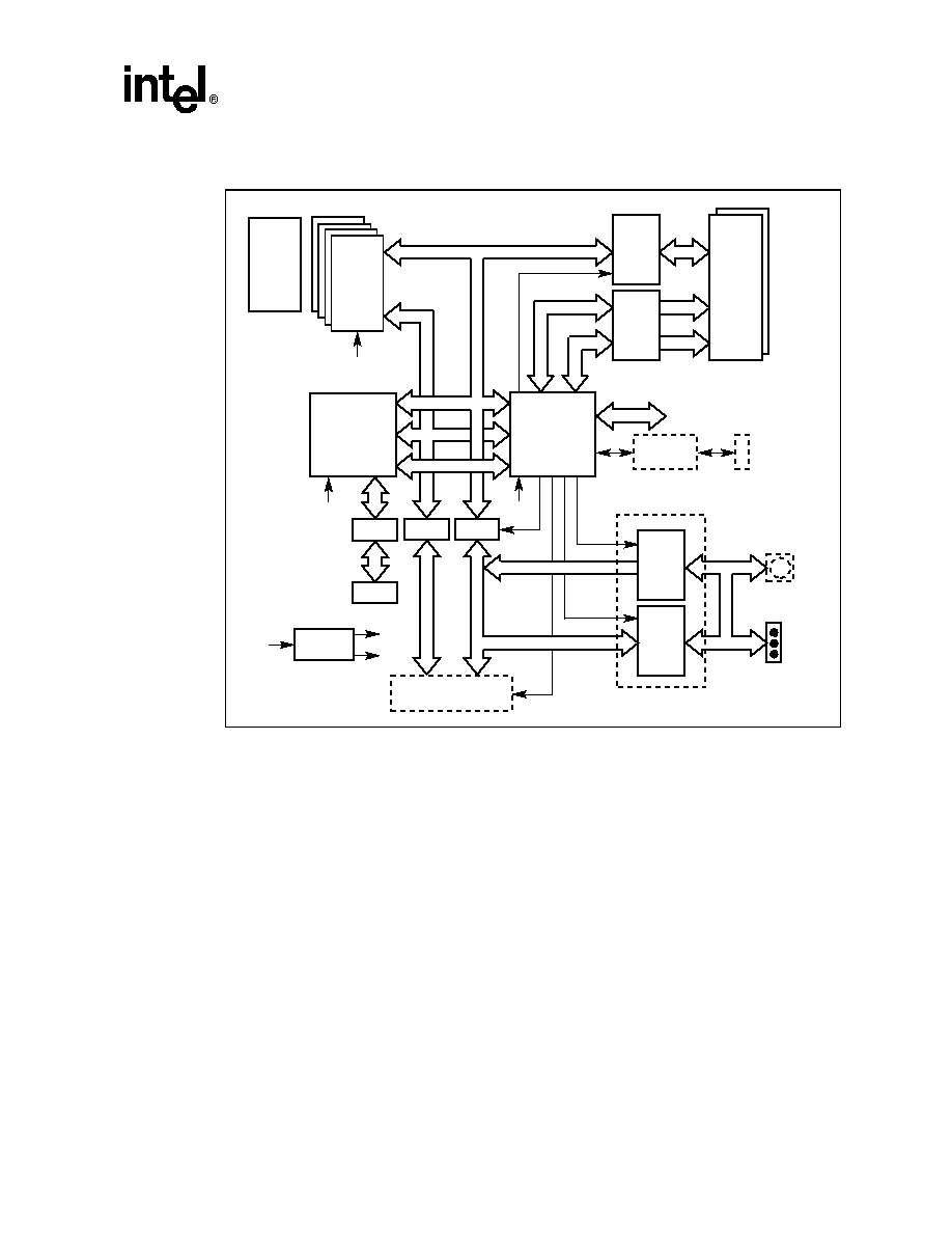
The EBSA-285 (see Figure 1) uses the SA-110 microprocessor as its CPU. It operates at speeds of
up to 233 MHz.
Brief Datasheet
5
StrongARM** SA-110/21285 Evaluation Platform
21285 Core Logic Chip
The 21285 is a core logic controller for the SA-110 microprocessor. It performs all of the control
functions on the EBSA-285.
Memory Subsystem
The EBSA-285 provides synchronous DRAM (SDRAM) for its main memory and flash ROM
(with nonvolatile storage) for its boot path. The EBSA-285 supports two SDRAM DIMM sockets;
one 16MB SDRAM DIMM is supplied. Nonvolatile storage is provided by four byte wide 1MB
flash ROMs, arranged to provide a 32-bit ROM path. This provides a total of 4MB of ROM. An
EPROM emulator is a debugging tool that connects to a target as though it were an EEPROM, but
allows fast download and modifications of code.
Figure 1. EBSA-285 Block Diagram
Buffer
21285
FM-06125.AI4
Buffer
SDRAM
DIMM
Command
D[31:0]
Flash
RAM
(32-Bit
Wide)
Buffer
Buffer
SA-110
Microprocessor
Buffer
JTAG
Clock
EPROM
Socket
(Byte
Wide)
D[31:0]
jtag
A[31:0]
Enable
Latch
Buffer
PCI-Bus
Clock
X-Bus Expansion
Headers
Regulator
+3.3 V
+2 V
+5 V
Enable
Enable
Enable
Enable
RS-232-C
Interface
COM0
Nine-Way
D-type
Connector
Flash Image
Selector Switch
Soft I/O
LEDs
+12 V

StrongARM** SA-110/21285 Evaluation Platform
6
Brief Datasheet
I/O Subsystem
All local I/O within the EBSA-285 is performed as programmed I/O under the control of the
SA-110. The I/O subsystem provides the following resources:
∑
An RS-232-C console port (data leads only) accessed via a nine-way D-type connector on the
bulkhead. This is referred to as COM0.
∑
An 8-bit I/O port that is used to control LEDs, read the state of jumpers, and contains a switch.
Interrupts
When the EBSA-285 is used as a host bridge (21285 configured as central function), logic in the
21285 acts as an interrupt controller for interrupts generated locally (on the module and within the
21285) and for interrupts generated by other devices on the PCI.
When the EBSA-285 is used as an add-in card, logic in the 21285 acts as an interrupt controller for
interrupts generated locally (on the module and within the 21285). In this mode, the SA-110 can
generate an interrupt to the host bridge (across the PCI bus) under software control. The interrupt is
routed out of the EBSA-285 as INTA#.
PCI Interface
The EBSA-285 has a 32-bit PCI interface that is compliant with Revision 2.1 of the PCI bus local
specification. It supports both 3.3-V and 5-V signaling.
Clocks
The EBSA-285 uses these oscillators:
∑
The 3.6864-MHz oscillator has two purposes. It drives the SA-110 phase-locked loop (PLL)
input, from which the SA-110 generates its core clock. It provides a fixed frequency input to
one of the timers in the 21285.
∑
The 50-MHz oscillator provides the osc clock input for the 21285. The 21285 buffers and
redrives this clock to generate the SA-110 bus clock, the SDRAM clocks, and the 21285
feedback clock (fclk). The local buses and the majority of the chip's internal logic run
synchronously at this clock frequency.
∑
The PCI clock is supplied by the backplane.
JTAG
The SA-110 and the 21285 both contain JTAG ports that allow test access to the I/O pins of the
device.

Brief Datasheet
7
StrongARM** SA-110/21285 Evaluation Platform
Expansion
The I/O capabilities of the EBSA-285 can be expanded by the PCI interface and by expansion
headers of the buffered 21285 X-Bus.
Resets
The reset source at power-on is dependent on the configuration (host bridge or device) and is link
configurable. There are three sources of resets on the EBSA-285:
∑
Power-on reset
∑
Reset from the PCI
∑
Reset from 21285 watchdog timer
Power Requirements
The EBSA-285 has the following power requirements:
∑
+5 V +/- 5%
∑
+12 V +/- 5%
Onboard Power Generation
The EBSA-285 generates +3.3 V and +2 V using onboard circuitry.
Onboard Software
The EBSA-285 onboard software is programmed into the flash ROM. The flash ROM can contain
a number of independent images. At a minimum, the flash ROM contains a program called the
Primary Boot Loader (PBL). The PBL can load and start a specific image that is stored in flash
ROM and is selected by using the rotary flash image selector switch on the bulkhead mounting
bracket. By default, the PBL starts up the ARM remote debug agent.
An onboard diagnostic suite is also programmed into flash ROM and is always selected using
IMAGE1 on the rotary switch.
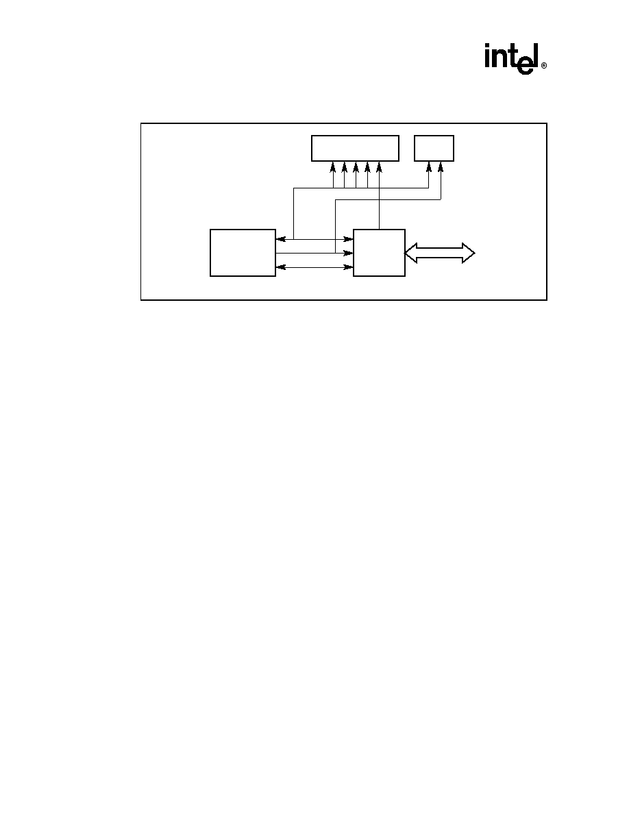
The 21285 core logic controller is part of the Intel provision of PCI I/O support for the StrongARM
family. Specifically, it is a support chip for the SA-110 StrongARM microprocessor, integrating an
SDRAM memory controller, PCI bus, UART (data leads only), timers, interrupt control, boot
ROM/flash, and low-speed (X-Bus) I/O in a single device. The chip supports an optional system
arbiter, which shares pins with the X-Bus control signals making it an either/or option. The LEDs
and rotary switch (X-Bus peripherals) are not accessible if the arbiter is configured rather than the
X-Bus. Figure 2 shows a diagram of the 21285 and SA-110 in a host bridge application.
StrongARM** SA-110/21285 Evaluation Platform
8
Brief Datasheet
PCI Backplane Application
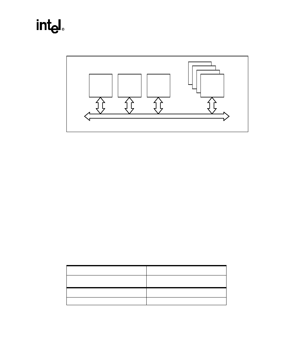
The EBSA-BPL PCI passive backplane (see Figure 3) complements the EBSA-285 offering. The
backplane allows a wide variety of StrongARM (and mixed processor) configurations to be tested.
Specifically, it allows verification and evaluation of the 21285 and future PCI-related StrongARM
product line developments as system masters and intelligent devices in desktop/server
environments. The backplane provides the following:
∑
Support for all features on the EBSA-285 module.
∑
An environment for verification, evaluation, and benchmarking of StrongARM PCI support
with the widest range of peripherals. For this reason, the standard PCI I/O form factor adopted
by the PCI industry is used.
∑
The ability to use industry-standard enclosures and power supply units (PSUs).
∑
An environment for testing all current and future Intel (standard form factor assumed) PCI
peripheral cards from the PCI-to-PCI bridge (PPB) group, multimedia, and communications
business units of the StrongARM family. Of particular importance is interworking with the
PCI bridge evaluation boards, which allows a wide variety of bridged bus configurations to be
investigated and/or verified.
∑
64-bit support (for future proofing of the design).
∑
Two variants: EBSA-BPL-5V complying with the 5-V PCI signaling environment, and
EBSA-BPL-3V3 complying with the 3.3-V PCI signaling environment.
∑
Backplane provision for the PCI system clock and PCI arbitration from the EBSA-285 or other
EBSA-BPL compatible module.
∑
Optional support for PCI Industrial Computer Manufacturers Group (see the www.picmg.com
website for details) arbitration from the EBSA-285 module.
Figure 2. 21285 Host Bridge Application Diagram
PCI Bus
SA-110
Microprocessor
D[31:0]
A[31:0]
Control
21285
Address,
Control
Synchronous DRAM
Memory
ROM
FM-05671.AI4
Brief Datasheet
9
StrongARM** SA-110/21285 Evaluation Platform
Main Components of PCI Backplane
The main components of the PCI backplane include the following:
∑
5 each 64-bit PCI slots
-- System slot with PICMG arbiter support.
-- Four standard PCI slots for devices.
∑
Two backplane variants
-- 5-V signaling
-- 3.3-V signaling
∑
Two PCI arbitration options
-- Via system slot
-- Backplane arbiter
∑
Backplane clock (25, 27.5, 30, and 33.33 MHz)
∑
AT desktop chassis compatible
∑
PC-AT or VRM supply options
Figure 3. EBSA-BPL PCI Passive Backplane Block Diagram
64-Bit
PCI
System
Slot
Arbiter
Clocks
64-Bit
PCI
Slots
(4)
FM-06124.AI4
64-Bit PCI Bus
Table 1. EBSA-285 Characteristics
Electrical
Power supply
5 V ±5%
12 V ±5%
Physical
Package
Form factor PCI add-in card
Support, Products, and Documentation
If you need technical support, a Product Catalog, or help deciding which documentation best meets
your needs, visit the Intel World Wide Web Internet site:
http://www.intel.com
Copies of documents that have an ordering number and are referenced in this document, or other
Intel literature may be obtained by calling 1-800-332-2717 or by visiting Intel's website for
developers at:
http://developer.intel.com
You can also contact the Intel Massachusetts Information Line or the Intel Massachusetts Customer
Technology Center. Please use the following information lines for support:
For documentation and general information:
Intel Massachusetts Information Line
United States:
1≠800≠332≠2717
Outside United States:
1≠303-675-2148
Electronic mail address:
techdoc@intel.com
For technical support:
Intel Massachusetts Customer Technology
Center
Phone (U.S. and international):
1≠978≠568≠7474
Fax:
1≠978≠568≠6698
Electronic mail address:
techsup@intel.com