 | –≠–ª–µ–∫—Ç—Ä–æ–Ω–Ω—ã–π –∫–æ–º–ø–æ–Ω–µ–Ω—Ç: FMB | –°–∫–∞—á–∞—Ç—å:  PDF PDF  ZIP ZIP |

MODELS
I
NPUT
V
OLTAGE
AND
C
URRENT
B5-3
Input (V)
0 - 40
0 - 40
0 - 40
Current ( A)
1.75
3.8
5.0
DESCRIPTION
The FM-461, FMA-461, and FMB-461 EMI filter modules have been
specifically designed to reduce the input line reflected ripple current
of Interpoint's MTO, MTW, MHE, MLP, and MFW Series of DC/DC
converters. They are intended for use in applications of high
frequency ( 100 kHz) switch-mode DC/DC converters which must
meet MIL-STD-461C levels of conducted power line noise.
These filters are built using thick-film hybrid technology and are
sealed in metal packages for military, aerospace, and other high-
reliability applications. See Section B8, cases H3, H5, K4, and K6
for dimensions. See Section C2 for screening options.
MIL-STD N
OISE
M
ANAGEMENT
When used in conjunction with Interpoint's DC/DC converters (see
connection diagram, Figure 2), the input ripple current will be
reduced by 40 dB within the frequency band of 100 kHz to 50 MHz.
This gives the filter/converter combination a performance which
exceeds the CE03 test limit of MIL-STD-461C. The CE03 perform-
ance of a model MHE2805S converter with and without the FM-461
filter is shown in Figures 6 and 7.
F
ILTER
O
PERATION
A fast-reacting (1 picosecond) transient suppressor clamps the input
voltage at approximately 47 V, protecting the DC/DC converter from
line induced transients.
The filters are rated to operate, with no degradation of performance,
over the temperature range of ≠55∞C to +85∞C (as measured at the
baseplate). Above 85∞C, input voltage and current must be derated
as specified in "Derating" on the following page. The maximum
power dissipation of the filters at maximum input current represents
a power loss of less than 3% at typical input voltage.
L
AYOUT
R
EQUIREMENTS
The case of the filter must be connected to the case of the converter
through a low impedance connection to minimize EMI.
EMI I
NPUT
F
ILTERS
28 V
OLT
I
NPUT
FM-461, FMA-461
AND FMB-461
EMI FILTERS
1.75 TO 5 AMP
F
EATURES
∑ ≠55∞C to +85∞C operation
∑ 0 to 40 VDC volt input
∑ Up to 40 dB attenuation
110 kHz to 50 MHz
∑ Transient suppression
∑ Compliant to
MIL-STD-461C, CE03
Size (max.): Non-flanged case H3 or H5
2.125 x 1.125 x 0.495* inches (53.98 x 28.58 x 12.57* mm)
Flanged case K4 or K6
2.910 x 1.125 x 0.495* inches (73.91 x 28.58 x 12.57* mm)
See Section B8, cases H3, H5, K4, and K6, for dimensions.
*Height varies depending on model.
Weight:
Maximum ≠ FM-461 38 grams, FMA-461 42 grams, FMB-461 43 grams
Screening: Standard or ES. See Section C2 for screening options, see Section A5
for ordering information.

RECOMMENDED
OPERATING CONDITIONS
DERATING
ABSOLUTE MAXIMUM RATINGS
Input Voltage
∑ 0 to 40 VDC continuous
Lead Soldering Temperature (10 sec per lead)
∑ 300∞C
Storage Temperature Range (Case)
∑ ≠55∞C to +135∞C
Isolation
∑ 100 megohm minimum at 500 V
∑ Any pin to case (except case pin)
B5-4
FM-461 EMI FILTER
1.75 TO 5 AMP
Input Voltage Range
∑ 0 to 40 VDC continuous
Case Operating Temperature (Tc)
∑ ≠55∞C to +85∞C full power
∑ ≠55∞C to +125∞C absolute
Electrical Characteristics: 25∞C Tc, nominal Vin, unless otherwise specified.
EMI I
NPUT
F
ILTERS
FM-461
FMA-461
FMB-461
PARAMETER
CONDITION
MIN
TYP
MAX
MIN
TYP
MAX
MIN
TYP
MAX
UNITS
INPUT VOLTAGE
CONTINUOUS
0
28
40
0
28
40
0
28
40
VDC
INPUT CLAMPING
≠55∞C
38.9
43.2
47.5
38.9
43.2
47.5
38.9
43.2
47.5
VOLTAGE
+25∞C
42.3
47.0
51.7
42.3
47.0
51.7
42.3
47.0
51.7
VDC
+125∞C
44.9
49.9
54.8
44.9
49.9
54.8
44.9
49.9
54.8
INPUT CURRENT
DC
--
--
1.75
--
--
3.8
--
--
5.0
A
RIPPLE
--
--
0.67
--
--
1.0
--
--
1.2
A rms
NOISE
REJECTION
15 kHz - 50 MHz
--
40
--
--
40
--
--
40
--
dB
DC RESISTANCE
(R
DC
) STEADY STATE
--
0.38
0.42
0.07
0.10
0.15
0.07
0.09
0.10
CAPACITANCE
ANY PIN TO CASE
1900
--
2200
3700
--
4400
6450
--
8000
pF
OUTPUT VOLTAGE
1
STEADY STATE
V
OUT
= V
IN
- I
IN
(R
DC
)
VDC
OUTPUT CURRENT
STEADY STATE
--
--
1.75
--
--
3.8
--
--
5.0
A
POWER
DISSIPATION
MAX. CURRENT
--
--
1.3
--
--
1.6
--
--
2.5
W
Note
1. Typical applications result in Vout within 2% of Vin.
Input Voltage
Derate linearly from 100% at 85∞C case to
the 33 VDC at 125∞C case
Input Ripple Current
Derate linearly from 100% at 85∞C case to
the following at 125∞C case
270 mA rms FM-461
400 mA rms FMA-461
480 mA rms FMB-461
DC Input and Output Current
Derate linearly from 100% at 85∞C case to
the following at 125∞C case
750 mA FM-461
1.7 A FMA-461
1.7 A FMB-461
x2
0.1 F
0.01 F
0.001 F
4.7 F
150
47 pF
1000 pF
50
1000 pF
500 V
Positive
Input
Input
Common
Positive
Output
Output
Common
FM-461
469 H
2.4 H
F
IGURE
1: S
CHEMATIC

B5-5
FM-461 EMI FILTER
1.75 TO 5 AMP
EMI I
NPUT
F
ILTERS
+Vin
+Vout
Input
Common
Output
Common
Case
R
L
R
L
EMI FILTER
DC/DC CONVERTER
+Vin
+Vout
Input
Common
Output
Common
Case
Chassis
ground
Multiple units
allowed up to
rated output
current of filter
The case ground connection should be as low an impedance as possible to minimize EMI. Direct contact of
baseplate to chassis ground provides the lowest impedance.
F
IGURE
4: C
ONNECTION
D
IAGRAM
x3
x2
0.1 F
0.01 F
0.001 F
x2
x2
4.7 F
150
47 pF
1000 pF
50
1000 pF
500 V
Positive
Input
Input
Common
Positive
Output
Output
Common
FMA-461
2.4 H
>150 H
F
IGURE
2: S
CHEMATIC
4.7 F
3300 pF
500 V
Positive
Input
Input
Common
Positive
Output
Output
Common
FMB-461
3.5 H
9.4 F
0.65
3.5 H
50
47 pF
500V
P6KE47
18.8 F
F
IGURE
3: S
CHEMATIC

B5-6
Typical Performance Curves: 25∞C Tc , nominal Vin, unless otherwise specified.
90
70
50
30
.015
.1
1
10
50
10
EMISSION LEVEL (dmA)
FREQUENCY (MHz)
CE03 Limit
F
IGURE
6
90
70
50
30
.015
.1
1
10
50
10
EMISSION LEVEL (dmA)
FREQUENCY (MHz)
CE03 Limit
F
IGURE
7
FM-461 EMI FILTER
1.75 YO 5 AMP
EMI I
NPUT
F
ILTERS
MHE Converter Without Filter
MHE Converter With FM-461 EMI Filter
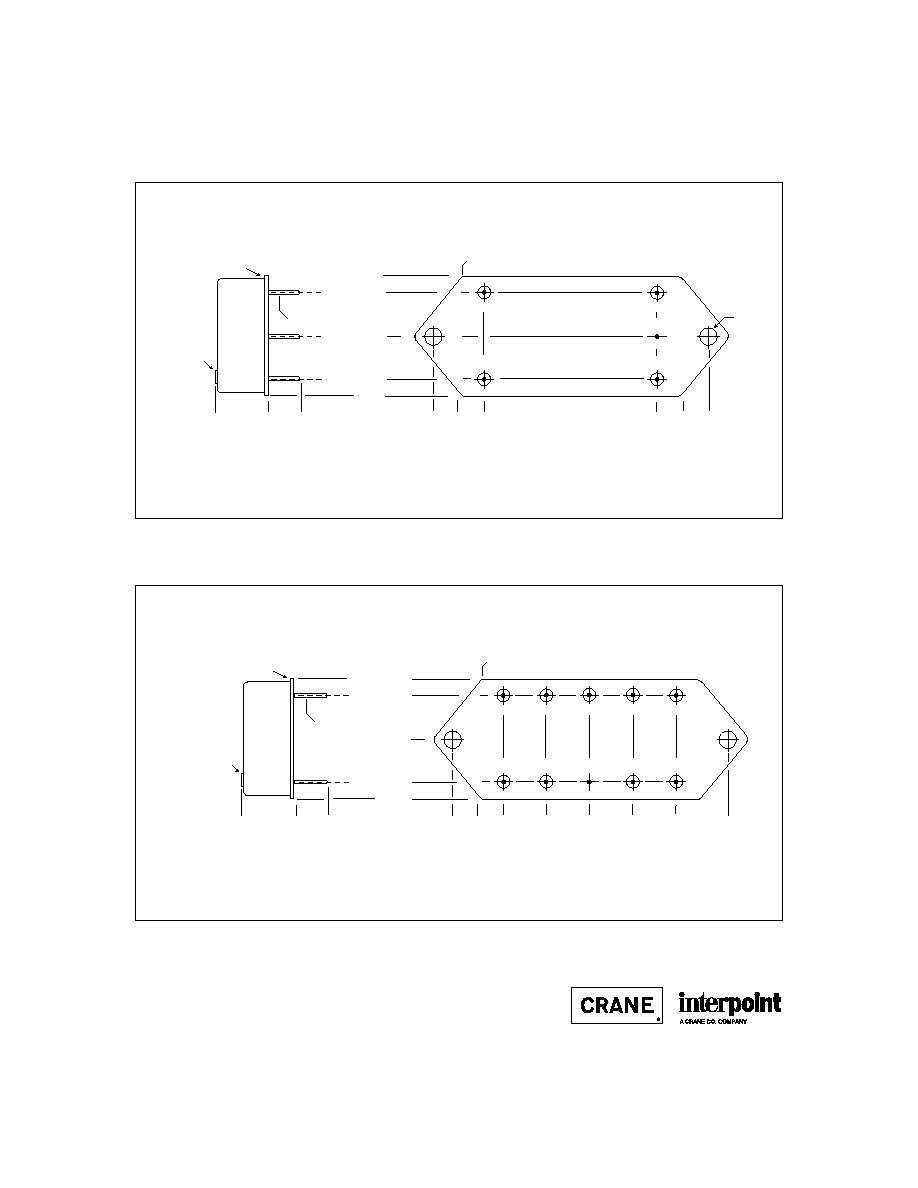
PIN OUT
1
2
3
4
5
Squared corner and dot on top
of package indicate pin one.
BOTTOM VIEW
FM-461, FMA-461, FMB-461
Dotted line outlines flanged package option.
FMB - 461 F / ES
Base Model
MIL-STD-461 reference
Screening
FM, FMA, or FMB
(Standard screening has no designator
in this position)
Case Option
(Non-flanged case has no designator in
this position)
MODEL NUMBERING KEY
See Section B8, cases H3, H5, K4, and K6, for dimensions.
Pin
Designation
1
Positive Input
2
Positive Output
3
Case Ground
4
Output Common
5
Input Common
F
IGURE
5: P
IN
O
UT
26221-001-DTS Rev A
DQ# 14006
All technical information is believed to be accurate, but no responsibility is
assumed for errors or omissions. Interpoint reserves the right to make changes in
products or specifications without notice. Copyright © 1990 - 1999 Interpoint. All
rights reserved.

B8-17
CASE H
C
ASES
CASE H
BOTTOM VIEW
See Figures 29 ≠ 34
for pin configurations.
2.125 max
(53.98)
1.125 max
(28.58)
Materials
Header Cold Rolled Steel/Nickel/Gold
cases H1 and H2
Cold Rolled Steel/Nickel/Tin
cases H3, H4, and H5
Cover Kovar/Nickel
cases H1 and H2
Cold Rolled Steel/Nickel/Tin
cases H3, H4, and H5
Pins #52
alloy
ceramic seal
case H1
case H2 (except MHV Series Single and Dual)
compression glass seal
MHV Series Single and Dual
case H3, H4, H5
Case dimensions in inches (mm)
Tolerance
±
0.005 (0.13) for three decimal places
±
0.01 (0.3) for two decimal places
unless otherwise specified
CAUTION
Heat from reflow or wave soldering may damage
the device. Solder pins individually with heat
application not exceeding 300
∞
C for 10 seconds
per pin.
Dot on top of case indicates pin one
0.155 (3.94)
0.955 (24.26)
Seam Seal
0.000
0.040 dia
(1.02)
0.000
0.000
0.400 max.
(10.16)
0.25
±
0.03
(6.4
±
0.8)
0.555 (14.1)
0.245
(6.22)
1.845
(46.86)
2.090
(53.01)
1.110 (28.19)
1
2
3
4
5
FMC EMI Filter: Screening ≠ Standard, ES, or 883
SFMC EMI Filter: Screening ≠ Space Standard, H, or K
BOTTOM VIEW CASE H1
Squared corner and dot on top
of case indicate pin one.
F
IGURE
29: C
ASE
H1
F
IGURE
28: C
ASE
H M
AXIMUM
D
IMENSIONS
Note: Although every effort has been made to render the case drawings at actual size, variations in the printing process may cause some distortion. Please refer
to the numerical dimensions for accuracy.

B8-19
CASE H
C
ASES
0.160 (4.06)
0.960 (24.38)
Solder Seal
Solder Tip-off
0.000
0.040 dia
(1.02)
0.000
0.000
0.25 +0.05/-0.00
(6.4 +1.3/-0.0)
0.560 (14.22)
0.255
(6.48)
1.855
(47.12)
2.110
(53.59)
1.120 (28.45)
1
2
4
5
FM-461 EMI Filter: Screening ≠ Standard of ES
BOTTOM VIEW CASE H3
0.417 max (10.59)
Squared corner and dot on top
of case indicate pin one.
3
F
IGURE
31: C
ASE
H3

B8-21
CASE H
C
ASES
0.160 (4.06)
0.960 (24.38)
Solder Seal
Solder Tip-off
0.000
0.040 dia
(1.02)
0.000
0.000
0.25 +0.05/-0.00
(6.4 +1.3/-0.0)
0.560 (14.22)
0.255
(6.48)
1.855
(47.12)
2.110
(53.59)
1.120 (28.45)
1
2
4
5
FMA-461and FMB-461 EMI Filter: Screening ≠ Standard of ES
BOTTOM VIEW CASE H5
0.495 max (12.57)
Squared corner and dot on top
of case indicate pin one.
3
0.160 (4.06)
0.960 (24.38)
0.655
(16.64)
1.055
(26.80)
1.455
(36.96)
0.000
0.000
0.255
(6.48)
1.855
(47.12)
2.110
(53.59)
1.120 (28.45)
1
2
6
10
MHE Series: Screening ≠ Standard or ES
BOTTOM VIEW CASE H6
3
4
5
7
8
9
0.040 dia
(1.02)
0.25 +0.05/-0.00
(6.4 +1.3/-0.0)
Solder Seal
Solder Tip-off
0.000
0.495 max (12.57)
Dot on top of case indicates pin one
HR151 Series and HR152 Series: no screening options
F
IGURE
34: C
ASE
H6
F
IGURE
33: C
ASE
H5

B8-26
CASE K
C
ASES
Materials
Header Case K1 - K3
Cold Rolled Steel/Nickel/Gold
Cases K4 - K8
Cold Rolled Steel/Nickel/Tin
Cover
Case K1 - K3
Kovar/Nickel
Case K4 - K8
Cold Rolled Steel/Nickel/Tin
Pins
#52 alloy (all cases)
Case K1, K2, and K3 (except MHV Series Single and Dual)
ceramic seal
Cases K4 - K8 and MHV Series Single and Dual (K3)
compression glass seal
Case dimensions in inches (mm)
Tolerance
±
0.005 (0.13) for three decimal places
±
0.01 (0.2) for two decimal places
unless otherwise specified
CASE K
BOTTOM VIEW
See Figures 42 - 48
for pin configuration
CAUTION
Heat from reflow or wave soldering may damage
the device. Solder pins individually with heat
application not exceeding 300
∞
C for 10 seconds
per pin.
Flange Thickness:
Cases K1, K2, K3 and MLP Series (K5)
0.060 (1.52)
Cases K4, K5 (except MLP Series), K6, K7, and K8
0.067 +0.005/-0.007 (1.70 +0.13/-0.8)
1.125 max
(28.58)
2.910 max
(73.91)
Dot on top of case indicates pin one
F
IGURE
41: C
ASE
K M
AXIMUM
D
IMENSIONS

B8-29
CASE K
C
ASES
0.155 (3.94)
0.955 (24.26)
0.000
0.040 dia
(1.02)
0.000
0.000
0.25
±
0.03
(6.4
±
0.8)
0.555 (14.1)
0.245
(6.22)
1.845
(46.86)
1.115 (28.32)
1
2
4
5
Flanged case: Designator required in Case Option position of model number.
FM-461 EMI Filter: Screening ≠ Standard or ES
BOTTOM VIEW CASE K4
0.162 dia
(4.11)
0.230
(5.84)
2.320
(58.93)
Solder Seal
Solder Tip-off
0.417 max
(10.59)
Squared corner and dot on top
of case indicate pin one.
3
F
IGURE
45: C
ASE
K4
0.155 (3.94)
0.955 (24.26)
6
10
7
8
9
0.000
0.25
±
0.03
(6.4
±
0.8)
0.040 dia
(1.02)
0.155 (3.94)
0.955 (24.26)
Solder Seal
All K5
cases
Solder Tip-off
0.417 max (10.59)
0.000
0.000
0.245
(6.22)
≠ 0.230
(5.84)
1.845
(46.86)
2.320
(58.93)
0.230
(5.84)
2.320
(58.93)
1.115 (28.32)
1
2
6
10
Flanged cases: Designator required in Case Option position of model number.
MTR Series Dual and MLP Series: Screening ≠ Standard or ES
BOTTOM VIEW CASE K5
3
4
5
7
8
9
0.000
0.245
(6.22)
1.845
(46.86)
1
2
3
4
5
0.645
(16.38)
1.045
(26.54)
1.445
(36.70)
0.645
(16.38)
1.045
(26.54)
1.445
(36.70)
0.555 (14.1)
0.000
1.115 (28.32)
0.555 (14.1)
Squared corner and dot on top
of case indicate pin one.
Squared corner and dot on top
of case indicate pin one.
MLP Series
MTR Series Dual
(Standard and ES)
F
IGURE
46: C
ASE
K5
B8-30
CASE K
C
ASES
0.155 (3.94)
0.955 (24.26)
0.000
0.040 dia
(1.02)
0.000
0.000
0.25
±
0.03
(6.4
±
0.8)
0.555 (14.1)
0.245
(6.22)
1.845
(46.86)
2.090
(53.01)
1.115 (28.32)
1
2
4
5
Flanged cases: Designator required in Case Option position of model number.
FMA-461 and FMB-461 EMI Filters: Screening ≠ Standard or ES
BOTTOM VIEW CASE K6
0.162 dia
(4.11)
0.230
(5.84)
2.320
(58.93)
Solder Seal
Solder Tip-off
0.495 max (12.57)
Squared corner and dot on top
of case indicate pin one.
3
F
IGURE
47: C
ASE
K6
0.155 (3.94)
0.955 (24.26)
0.000
0.25
±
0.03
(6.4
±
0.8)
0.040 dia
(1.02)
Solder Seal
Solder Tip-off
0.495 max (12.57)
0.000
0.000
0.245
(6.22)
≠ 0.230
(5.84)
1.845
(46.86)
2.320
(58.93)
1.115 (28.32)
1
2
6
10
Flanged case: Designator required in Case Option position of model number.
MHE Series: Screening ≠ Standard or ES
BOTTOM VIEW CASE K7
3
4
5
7
8
9
0.645
(16.38)
1.045
(26.54)
1.445
(36.70)
0.555 (14.1)
Squared corner and dot on top
of case indicate pin one.
F
IGURE
48: C
ASE
K7

C2-12
QA SCREENING
85∞C PRODUCTS
TEST (85∞C Products excluding HR products)
STANDARD
/ES
PRE-CAP INSPECTION
Method 2017
yes
yes
TEMPERATURE CYCLE (10 times)
Method 1010, Cond. B, -55∞C to 125∞C
no
yes
CONSTANT ACCELERATION
Method 2001, 500 g
no
yes
BURN-IN
96 hours at 70∞C ambient (typical)
no
yes
FINAL ELECTRICAL TEST MIL-PRF-38534, Group A
Subgroups 1 and 4: +25∞C case
yes
yes
HERMETICITY TESTING
Fine Leak, Method 1014, Cond. A
no
yes
Gross Leak, Method 1014, Cond. C
no
yes
Gross Leak, Dip (1 x 10
-3
)
yes
no
FINAL VISUAL INSPECTION
Method 2009
yes
yes
Test methods are referenced to MIL-STD-883 as determined by MIL-PRF-38534.
MFW Series
MTW Series
MHE/MLP Series
MHL Series
MRH Series
MTO Series
MSR Series
DCH Series
FM/FMA/FMB EMI Filters
MSF EMI Filter
85∞C P
RODUCTS
Applies to the following products: