
MODELS
I
NPUT
V
OLTAGE
AND
C
URRENT
B3-7
Input (V)
28
28
270
270
Current ( A)
7.0
15.0
0.7
1.5
DESCRIPTION
The FMD SeriesTM and FME SeriesTM EMI filters are specifically
designed to reduce the reflected input ripple current of Interpoint's
high frequency DC/DC converters. FMD/FME filters minimize elec-
tromagnetic interference (EMI) for the MHE, MHL, MLP, MRH, MTO,
MHF, MHF+, MHV, MHD, MTR, MFL, MHP, and MFLHP Series.
These filters are intended for use in 28 or 270 volt applications
which must meet MIL-STD-461C, CE03 levels of conducted emis-
sions. One filter can be used with multiple converters up to the rated
output current of the filter.
I
NPUT
R
IPPLE AND
EMI
Switching DC/DC converters naturally generate two noise compo-
nents on the power input line: differential noise and common mode
noise. Input ripple current refers to both of these components.
Differential noise occurs between the positive input and input
common. Most Interpoint converters have an input filter that reduces
differential noise which is sufficient for many applications. Common
mode noise occurs across stray capacitances between the
converter's power train components and the baseplate (bottom of
the package) of the converter.
Where low noise currents are required to meet CE03 of MIL-STD-
461, a power line filter is needed. The FMD/FME Series of EMI
power line filters reduces the common mode and differential noise
generated by the converters. FMD/FME-461 filters reduce input
ripple current by as much as 60 dB at 500 kHz and 55 dB at 1 MHz
when used in conjunction with Interpoint's DC/DC converters. See
Figures 8 and 9.
Place the filter as close as possible to the converter for optimum
performance. The baseplates of the filter and the converter should be
connected with the shortest and widest possible conductors. For the
best connection, mount the filter's and converter's baseplates on or
above a small ground plane. See Figure 5.
T
RANSIENTS
The transients listed below will not damage the filter but will be
passed on to the converter:
∑
All filters: ±600 volts (50 ohm source
impedance) for up to 10 µs.
∑
28 volt filter: ±100 volts (0.5 ohm source
impedance) for up to 100 ms.
∑
270 volt filter: ±500 volts (independent of
source impedance) for up to 100 ms.
O
PERATION OVER
T
EMPERATURE
All FMD/FME-461 Series filters are rated for full power operation
from ≠55∞C to +125∞C case temperature. Current is derated linearly
to zero at +135∞C case temperature.
I
NSERTION
L
OSS
The maximum dc insertion loss at full load and nominal input voltage
represents a power loss of less than 4%.
P
ACKAGING
FMD/FME-461 filters are sealed in metal hermetic side-leaded
packages. See Section B8, cases U1, U2, V, W, Y, and Z.
Additionally the FMD28-461 filter is available in a metal hermetic
down-leaded package (see Section B8, case J4).
L
AYOUT
R
EQUIREMENTS
The case of the filter must be connected to the case of the converter
through a low impedance connection to minimize EMI.
EMI I
NPUT
F
ILTERS
28 & 270 V
OLT
I
NPUT
FMD/FME EMI FILTER
0.7 TO 15 AMP
F
EATURES
∑ ≠55∞C to +125∞C operation
∑ Up to 60 dB attenuation
at 500 kHz.
∑ Compliant to
MIL-STD-461C, CE03
∑ Compatible with
MIL-STD-704E
DC power bus
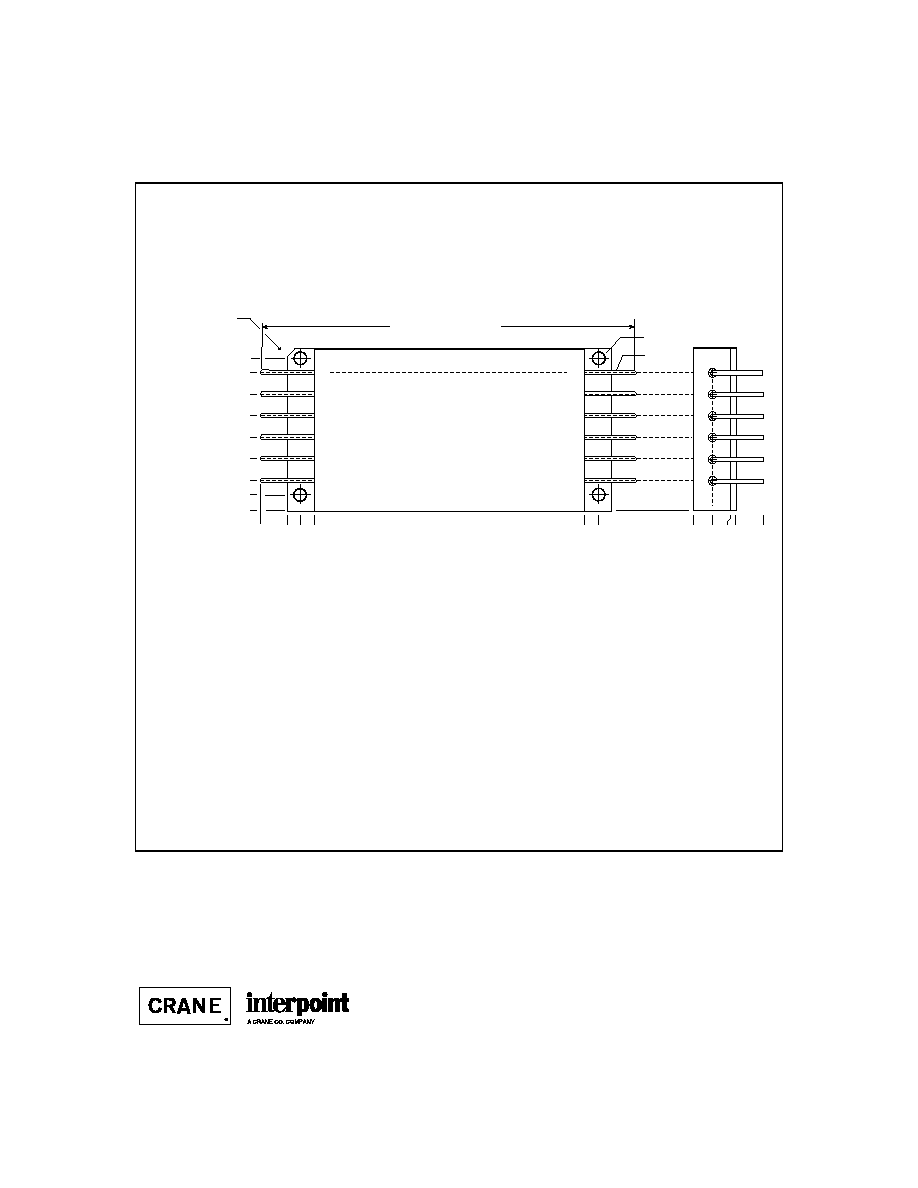
Size (max.): Case U2, FME all models; Case U1, FMD28-461SL and FMD270-461SL
3.005 x 1.505 x 0.400 inches (76.33 x 38.23 x 11.16 mm)
[FME models, shown in Case U2 (flanged, short leads). Also available:
Flanged ≠ leads bent down (case V); Tabbed ≠ leads bent up (case W), short
leads (case Y), and leads bent down (case Z).See Section B8, cases U2, V, W,
Y, and Z for dimensions and options.]
Case J4, FMD28-461
2.720 x 1.350 x 0.505 inches (69.09 x 34.29 x 12.83 mm)
See Section B8, cases J4, U1, U2, V, W, Y, and Z for dimensions.
Weight:
77 grams typical cases U1, U2, V, W, Y, and Z; 55 grams typical case J4
Screening: Standard, ES, or 883 (Class H).
See Section C2 for screening options, see Section A5 for ordering information.

ABSOLUTE MAXIMUM RATINGS
RECOMMENDED OPERATING CONDITIONS
Input Voltage
∑ 0 to 40 VDC continuous for 28 V models
∑ 0 to 400 VDC continuous for 270 V models
Lead Soldering Temperature (10 sec per lead)
∑ 300∞C
Storage Temperature Range (Case)
∑ ≠65∞C to +150∞C
Isolation
∑ 100 megohm minimum at 500 V, any pin to case
(except FMD downleaded case case pin)
B3-8
FMD/FME EMI FILTER
0.7 TO 15 AMP
Input Voltage Range
∑ 0 to 40 VDC continuous for 28 V models
∑ 0 TO 400 VDC continuous for 270 V models
Case Operating Temperature (Tc)
∑ ≠55∞C to +125∞C full power
∑ ≠55∞C to +135∞C absolute
Derating Input/Output Current
∑ Linearly from 100% at 125∞C to 0% at 135∞ C
Electrical Characteristics: 25∞C Tc, nominal Vin, unless otherwise specified.
EMI I
NPUT
F
ILTERS
FMD28-461
FMD270-461
FME28-461
FME270-461
PARAMETER
CONDITION
MIN
TYP
MAX
MIN
TYP
MAX
MIN
TYP
MAX
MIN
TYP
MAX
UNITS
INPUT VOLTAGE
CONTINUOUS
0
28
40
0
270
400
0
28
40
0
270
400
VDC
TRANSIENT 100 ms
1
≠100
--
100
≠500
--
500
≠100
--
100
≠500
--
500
V
NOISE 500
kHz
50
60
--
50
60
--
30
40
--
40
50
--
dB
REJECTION
1 MHz
45
55
--
45
55
--
40
50
--
45
55
--
DC RESISTANCE
MAX. CURRENT
(R
DC
) Tc=25∞C
--
--
0.12
--
--
5.0
--
--
0.07
--
--
2.0
Tc=125∞C
--
--
0.15
--
--
6.3
--
--
0.07
--
--
3.2
CAPACITANCE
ANY PIN TO CASE
--
20,000
--
--
30,000
--
--
60,000
--
--
60,000
--
pF
OUTPUT VOLTAGE STEADY STATE
V
OUT
= V
IN
- I
IN
(R
DC
)
VDC
OUTPUT CURRENT
STEADY STATE
--
--
7
--
--
0.7
--
--
15
--
--
1.5
A
POWER
MAX. CURRENT
DISSIPATION
Tc=25∞C
--
--
6.0
--
--
2.5
--
--
15.75
--
--
4.5
W
Tc=125∞C
--
--
7.4
--
--
3.1
--
--
15.75
--
--
7.2
Note
1. 28 V models = 0.5
source impedance, 270 V models = independent of source impedance.

B3-9
FMD/FME EMI FILTER
0.7 TO 15 AMP
EMI I
NPUT
F
ILTERS
6 F
50 V
0.015 F
500 V
Positive
Input
Input
Common
Positive
Output
Output
Common
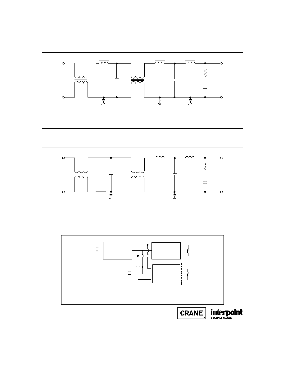
FME28-461
1.25 H
1.25 H
0.55 H
100 H
6 F
50 V
100 H
6 F
50 V
0.015 F
Positive
Input
Input
Common
Positive
Output
Output
Common
FME270-461
37 H
37 H
37 H
1.8 mH
0.68 F
0.68 F
1.3
1.8 mH
0.015 F
x2
x2
F
IGURE
1: FME28-461 S
CHEMATIC
≠ T
YPICAL
V
ALUES
F
IGURE
2: FME270-461 S
CHEMATIC
≠ T
YPICAL
V
ALUES
B3-10
FMD/FME EMI FILTER
0.7 TO 15 AMP
EMI I
NPUT
F
ILTERS
0.1 F
50 V
0.01 F
500 V
Positive
Input
Input
Common
Positive
Output
Output
Common
FMD28-461
4.1 H
4.1 H
4.1 H
135 H
6 F
50 V
10 F
50 V
1.3
135 H
0.015 F
500V
0.015 F
Positive
Input
Input
Common
Positive
Output
Output
Common
FMD270-461
18.5 H
18.5 H
0.68 F
0.68 F
1.3
0.015 F
844 H
844 H
+Vin
+Vout
Input
Common
Output
Common
Case
R
L
R
L
EMI FILTER
DC/DC CONVERTER
+Vin
+Vout
Input
Common
Output
Common
Case
Chassis
ground
Multiple units
allowed up to
rated output
current of filter
F
IGURE
5: C
ONNECTION
D
IAGRAM
F
IGURE
3: FMD28-461 S
CHEMATIC
≠ T
YPICAL
V
ALUES
F
IGURE
4: FMD270-461 S
CHEMATIC
≠ T
YPICAL
V
ALUES
The case ground connection between the filter and the converter should be as low an impedance as possible
to minimize EMI. Direct contact of baseplate to chassis ground provides the lowest impedance.
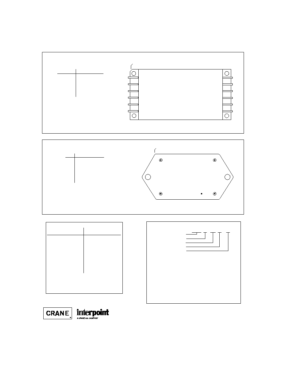
PIN OUT DOWN-LEADED MODEL
PIN OUT SIDE-LEADED MODELS
MODEL NUMBERING KEY
Angled corner and cover marking indicate pin one for cases U1, U2, and V.
Cover marking indicates pin one for cases W, Y and Z.
TOP VIEW
All FME models, FMD28-461SL,
and FMD270-461SL
(Pin side, marked side)
1
2
3
4
5
6
12
11
10
9
8
7
FME 28 - 461 V / 883
Base Model
Input Voltage
MIL-STD-461 Reference
Screening
Case/Lead Option*
(Standard screening has no designator
in this position.)
B3-11
FMD/FME EMI FILTER
0.7 TO 15 AMP
EMI I
NPUT
F
ILTERS
Outline shown is case U2, pin out is the same for all
side-leaded cases. Also available: flanged ≠ leads bent
down (case V); tabbed ≠ leads bent up (case W), short
leads (case Y), and leads bent down (case Z). See
Section B8, cases U1, U2, V, W, Y, and Z for dimensions.
Pin
1
Designation
1, 2, 3
Positive Input
4, 5, 6
Input Common
7, 8, 9
Output Common
10, 11, 12
Positive Output
--
Case Ground
2
Notes
1. All pins must be connected.
2. The baseplate is the only case ground connection and
should directly contact chassis ground.
FMD28-461SL, FMD270-461SL,
FME28-461, and FME270-461
F
IGURE
6: P
IN
O
UT
S
IDE
-L
EADED
M
ODELS
5
4
3
1
2
Squared corner and dot on top
of package indicate pin one.
BOTTOM VIEW
FMD28-461
F
IGURE
7: P
IN
O
UT
FMD28-461
See Section B8, case J4, for dimensions.
Pin
Designation
1
Positive Input
2
Positive Output
3
Output Common
4
Case Ground
1
5
Input Common
Note
1. Although down-leaded packages can be
connected to chassis ground with the case
ground lead, direct contact of the base plate to
chassis improves EMI performance.
DSCC NUMBERS
DSCC D
RAWING
(5915)
95004-01HXC
95004-01HTC
95004-01HUC
95004-01HYC
95004-01HZC
95009-01HXC
IN PROCESS
IN PROCESS
IN PROCESS
IN PROCESS
FME S
ERIES
S
IMILAR
P
ART
FME28-461/883
FME28-461W/883
FME28-461V/883
FME28-461Y/883
FME28-461Z/883
FME270-461/883
FME270-461W/883
FME270-461V/883
FME270-461Y/883
FME270-461Z/883
FMD28-461
For exact specifications for a DSCC product, refer to the
DSCC drawing. Contact your Interpoint representative for
status on the FME DSCC releases. See Section A3,
"SMD/DSCC Lists", for more information.
*Case/Lead Option: See section B8, cases J4, U1, U2, V, W, Y, and Z for
drawings and dimensions, see Section A5 for ordering information.
FME models: Case U2 has no designator in the case/lead option position.
To designate a case option add the case letter to the model number ≠
FME28-461V.
FMD models: Case J4 (down-leaded) has no designator in the case/lead-
option position. To designate case U1 (side-leaded) for the FMD place
"SL" in the case/lead option position ≠ FMD28-461SL. The 270 volt FMD
is only available in the side-leaded case ≠ FMD270-461SL.
B3-12
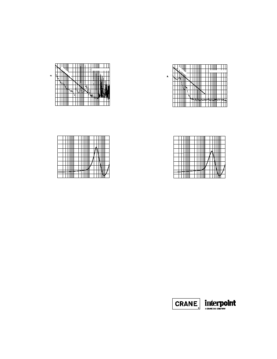
Typical Performance Curves: 25∞C Tc , nominal Vin, unless otherwise specified.
F
IGURE
11
FREQUENCY (kHz)
1.0
10
1.0
0.9
0.8
0.7
0.6
0.5
0.4
0.3
0.2
0.1
0.1
100
IMPEDANCE (OHMS)
DC BIAS: 10 AMP
FME28-461 OUTPUT IMPEDANCE
FREQUENCY (MHz)
EMISSION LEVEL (dB A
0.1
1
10
50
90
80
70
60
50
40
30
20
10
0
.015
CE03 LIMIT
NARROWBAND
F
IGURE
8
FREQUENCY (MHz)
EMISSION LEVEL (dB A)
0.1
1
10
50
90
80
70
60
50
40
30
20
10
0
.015
NARROWBAND
CE03 LIMIT
F
IGURE
9
F
IGURE
10
FREQUENCY (kHz)
1.0
10
1.0
0.9
0.8
0.7
0.6
0.5
0.4
0.3
0.2
0.1
0.1
100
IMPEDANCE (OHMS)
DC BIAS: 1 AMP
FME28-461 OUTPUT IMPEDANCE
FMD/FME EMI FILTER
0.7 TO 15 AMP
EMI I
NPUT
F
ILTERS
Three paralleled and synchronized MFL2815D
converters without filtering.
Three paralleled and synchronized MFL2815D
converters with an FME28-461.
22021-001-DTS Rev B (CaseJ4) DQ# 4002
All technical information is believed to be accurate, but no responsibility is assumed for
errors or omissions. Interpoint reserves the right to make changes in products or spec-
ifications without notice. FMD Series and FME Series are trademarks of Interpoint.
Copyright © 1992 - 1999 Interpoint. All rights reserved.
B8-36
CASE
CASE U
C
ASES
Materials
Header Cold Rolled Steel/Nickel/Gold
Cover
Kovar/Nickel
Pins #52
alloy/Gold
compression glass seal
Case dimensions in inches (mm)
Tolerance
±
0.005 (0.13) for three decimal places
±
0.01 (0.2) for two decimal places
unless otherwise specified
CAUTION
Heat from reflow or wave soldering may damage
the device. Solder pins individually with heat
application not exceeding 300
∞
C for 10 seconds
per pin.
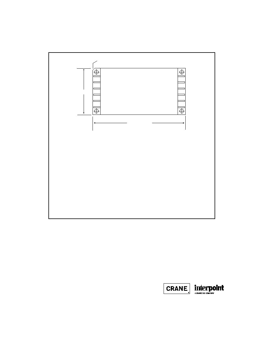
CASE U
TOP VIEW
(PIN SIDE)
See Figures 55 and 56 for dimensions
1.505 max (38.23)
3.005 (76.33) max.
Note: Pins are shown for Case U1.
Angled corner indicates pin one
F
IGURE
54: C
ASE
U M
AXIMUM
D
IMENSIONS

B8-38
CASE U
C
ASES
Angled corner
indicates pin one.
0.000
0.050 (1.27)
0.000
0.120 (3.05)
0.250 (6.35)
0.450 (11.43)
0.650 (16.51)
0.850 (21.59)
1.050 (26.67)
1.250 (31.75)
1.380 (35.05)
0.000
0.120 (3.05)
0.250 (6.35)
2.750 (69.85)
2.880 (73.15)
0.128 dia
(3.25).
0.040 dia
(1.02)
0.400 (10.16) max.
0.220 (5.59
Seam Seal
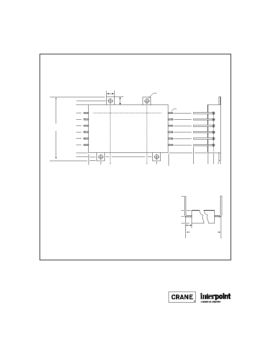
PIN-SIDE VIEW CASE U2*
(Flanged case, short leads)
MOR Series and FME EMI Filters: Screening ≠ Standard, ES, or 883
Also available in V, W, Y, and Z cases (Figures 57 - 60)
Pin Length
0.30
±
0.05
(7.6
±
1.3)
1
2
3
4
5
6
12
11
10
9
8
7
*No designator is required in the case option position, see Section A5, Ordering Information.
F
IGURE
56: C
ASE
U2
B8-39
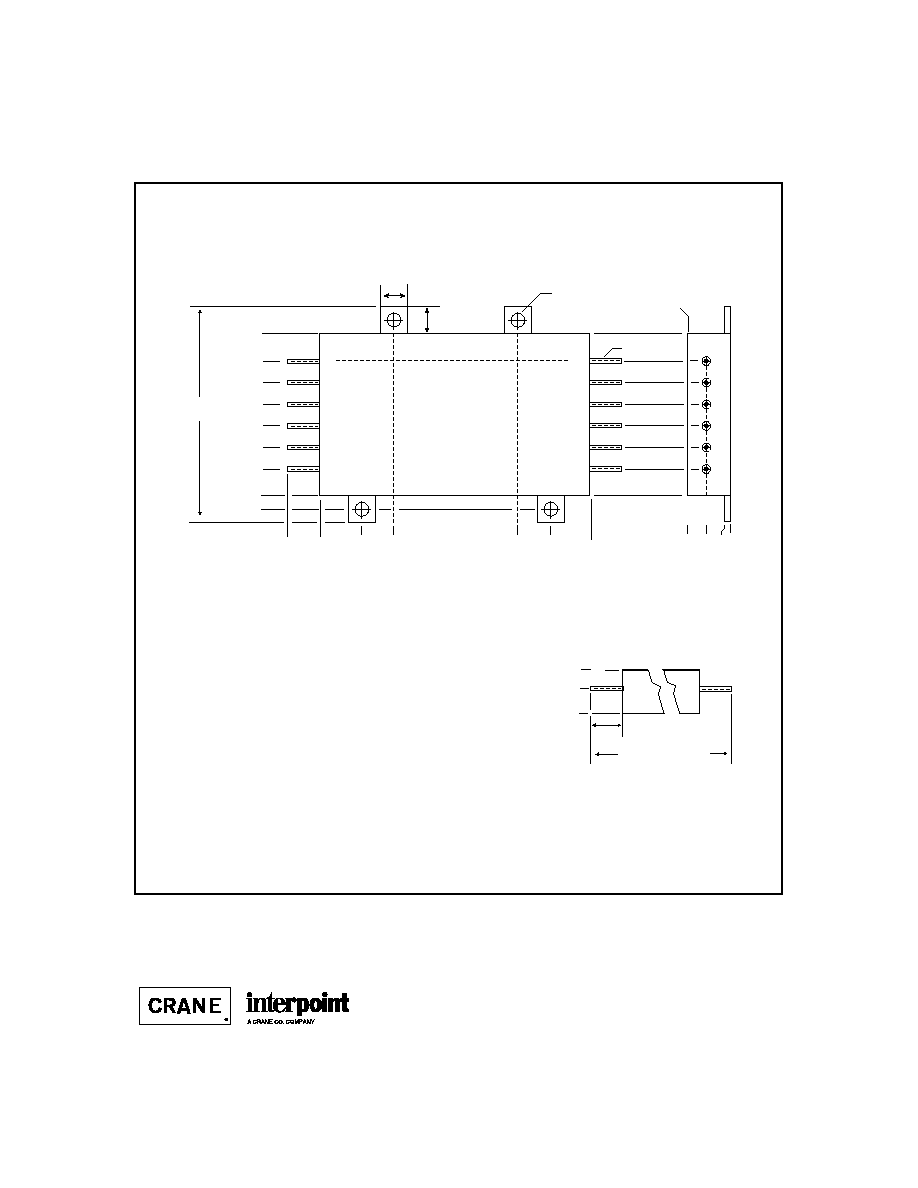
CASE V
C
ASES
0.000
0.220 (5.59)
0.050 (1.27)
0.400 (10.16) max
0.250 (6.35)
±
.050 (1.27)
0.225 (5.72
3.45 (87.6) Reference
(lead center to lead center)
0.000
0.120 (3.05)
0.250 (6.35)
0.450 (11.43)
0.650 (16.51)
0.850 (21.59)
1.050 (26.67)
1.250 (31.75)
1.380 (35.05)
0.000
0.120 (3.05)
0.250 (6.35)
2.750 (69.85)
2.880 (73.15)
0.128 dia (3.25)
0.040 dia
(1.02)
PIN-SIDE VIEW CASE V*
Flanged case, down leaded)
MOR Series and FME EMI Filters: Screening ≠ Standard, ES, or 883
Also available in U2, W, Y, and Z cases (Figures 56 and 58 - 60)
*Requires case option designator added to model number: MOR2805SV
See Section A5, Ordering Information.
1
2
3
4
5
6
12
11
10
9
8
7
Maximum dimensions: 3.005 x 1.505 (76.33 x 38.23 mm)
Materials
Header Cold Rolled Steel/Nickel/Gold
Cover
Kovar/Nickel
Pins #52
alloy/Gold
compression glass seal
Case dimensions in inches (mm)
Tolerance
±
0.005 (0.13) for three decimal places
±
0.01 (0.2) for two decimal places
unless otherwise specified
CAUTION
Heat from reflow or wave soldering may damage
the device. Solder pins individually with heat
application not exceeding 300
∞
C for 10 seconds
per pin.
Angled corner
indicates pin one.
F
IGURE
57: C
ASE
V
B8-40
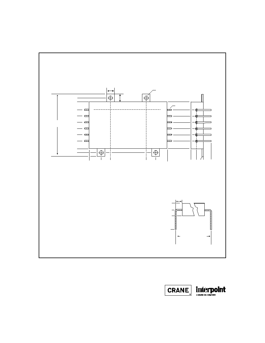
CASE W
C
ASES
1
2
3
4
5
6
12
11
10
9
8
7
0.040 dia
(1.02)
0.250 (6.35) Typ.
0.125
(3.18)
0.375
(9.53)
0.575
(14.61)
0.775
(19.69)
0.975
(24.77)
1.175
(29.85
1.375
(34.93)
1.625
(41.28)
2.125 (53.98)
0.375 (9.53)
0.140 dia
(3.56)
0.000
1.750 (44.45)
0.000
0.250 (6.35)
Typ.
1.450 (36.83)
0.300 (7.62)
1.750 (44.45)
2.000
(50.80)
PIN-SIDE VIEW CASE W*
(Tabbed case, up-leaded)
MOR Series and FME EMI Filters: Screening ≠ Standard, ES, or 883
Also available in U2, V, Y, and Z cases (Figures 56, 57, 59 and 60)
0.000
0.220 (5.59)
0.050 (1.27)
0.400 (10.16) max.
0.000
0.220 (5.59)
0.400 (10.16) max.
0.84
±
0.05
(21.3
±
1.3)
0.84
±
0.05
(21.3
±
1.3)
0.150 (3.81)
Lead Detail
2.80 (71.1) Reference
(lead center to lead center)
*Requires case option designator added to model number: MOR2805SW
See Section A5, Ordering Information.
Materials
Header Cold Rolled Steel/Nickel/Gold
Cover
Kovar/Nickel
Pins #52
alloy/Gold
compression glass seal
Case dimensions in inches (mm)
Tolerance
±
0.005 (0.13) for three decimal places
±
0.01 (0.2) for two decimal places
unless otherwise specified
CAUTION
Heat from reflow or wave soldering may damage
the device. Solder pins individually with heat
application not exceeding 300
∞
C for 10 seconds
per pin.
F
IGURE
58: C
ASE
W
B8-41
CASE Y
C
ASES
Bathtub
Seam Seal
0.250 (6.35) Typ.
0.125
(3.18)
0.375
(9.53)
0.575
(14.61)
0.775
(19.69)
0.975
(24.77)
1.175
(29.85
1.375
(34.93)
1.625
(41.28)
2.125 (53.98)
0.375 (9.53)
0.140 dia
(3.56)
0.000
1.750 (44.45)
0.000
0.250 (6.35)
Typ.
1.450 (36.83)
0.300 (7.62)
1.750 (44.45)
2.000
(50.80)
0.000
0.220 (5.59)
0.050 (1.27)
0.400 (10.16)
max.
PIN-SIDE VIEW CASE Y*
(Tabbed case, straight leads)
MOR Series and FME EMI Filters: Screening ≠ Standard, ES, or 883
Also available in U2, V, W, and Z casee (Figures 56, 57, 58 and 60)
0.000
0.220 (5.59)
0.400 (10.16) max.
0.30
±
0.05
(7.6
±
1.3)
Lead Detail
Pin Length
0.30
±
0.05
(7.6
±
1.3)
3.10 (78.7) Reference
*Requires case option designator added to model number: MOR2805SY
See Section A5, Ordering Information.
0.040 dia
(1.02)
1
2
3
4
5
6
12
11
10
9
8
7
Materials
Header Cold Rolled Steel/Nickel/Gold
Cover
Kovar/Nickel
Pins #52
alloy/Gold
compression glass seal
Case dimensions in inches (mm)
Tolerance
±
0.005 (0.13) for three decimal places
±
0.01 (0.2) for two decimal places
unless otherwise specified
CAUTION
Heat from reflow or wave soldering may damage
the device. Solder pins individually with heat
application not exceeding 300
∞
C for 10 seconds
per pin.
F
IGURE
59: C
ASE
Y
B8-42
CASE Z
C
ASES
0.250 (6.35) Typ.
0.125
(3.18)
0.375
(9.53)
0.575
(14.61)
0.775
(19.69)
0.975
(24.77)
1.175
(29.85
1.375
(34.93)
1.625
(41.28)
2.125 (53.98)
0.375 (9.53)
0.140 dia
(3.56)
0.000
1.750 (44.45)
0.000
0.250 (6.35)
Typ.
1.450 (36.83)
0.300 (7.62)
1.750 (44.45)
2.000
(50.80)
PIN-SIDE VIEW CASE Z*
(Tabbed case, down-leaded)
MOR Series and FME EMI Filters: Screening ≠ Standard, ES, or 883
Also available in U2, V, Y, and W cases (Figures 56, 57, 58 and 59)
*Requires case option designator added to model number: MOR2805SZ
See Section A5, Ordering Information.
0.000
0.220 (5.59)
0.050 (1.27)
0.400 (10.16) max.
0.000
0.220 (5.59)
0.400 (10.16) max.
0.36
±
0.05
(9.1
±
0.13)
0.150 (3.81)
Lead Detail
2.80 (71.1) Reference
(lead center to lead center)
0.36
±
0.05
(9.1
±
0.13)
0.040 dia
(1.02)
1
2
3
4
5
6
12
11
10
9
8
7
Materials
Header Cold Rolled Steel/Nickel/Gold
Cover
Kovar/Nickel
Pins #52
alloy/Gold
compression glass seal
Case dimensions in inches (mm)
Tolerance
±
0.005 (0.13) for three decimal places
±
0.01 (0.2) for two decimal places
unless otherwise specified
CAUTION
Heat from reflow or wave soldering may damage
the device. Solder pins individually with heat
application not exceeding 300
∞
C for 10 seconds
per pin.
F
IGURE
60: C
ASE
Z

B8-37
CASE U
C
ASES
Angled corner
indicates pin one.
1
2
3
4
5
6
12
11
10
9
8
7
0.000
0.050 (1.27)
0.000
0.120 (3.05)
0.250 (6.35)
0.450 (11.43)
0.650 (16.51)
0.850 (21.59)
1.050 (26.67)
1.250 (31.75)
1.380 (35.05)
1.505 (38.23) max.
0.000
0.120 (3.05)
0.250 (6.35)
2.750 (69.85)
2.880 (73.15)
3.005 (76.33) max.
0.128 dia
(3.25).
0.040 dia
(1.02)
0.23 (5.8) Lead Length
0.400 (10.16)
max.
0.220 (5.59
TOP VIEW CASE U1
MFL Series and MHP Series: Screening ≠ Standard, ES or 883
MFLHP Series, FMD270 EMI Filter, and FMD28-461SL EMI Filters:
Screening ≠ Standard or ES
SMFL, SMFLHP, SMHP, and SSP Series; SFCS, and SFME EMI Filters:
Screening ≠ Standard, Class H or K
HUM70 Module and LCM Module: Screening ≠ Standard or ES
Seam Seal
F
IGURE
55: C
ASE
U1
B8-22
CASE J
C
ASES
Materials
Header Case J1
Cold Rolled Steel/Nickel/Gold
Cases J2 - J5
Cold Rolled Steel/Nickel/Tin
Cover Case
J1
Kovar/Nickel
Case J2 - J5
Cold Rolled Steel/Nickel/Tin
Pins
#52 alloy (all cases)
Case J1
MHV Series Triple ≠ compression glass seal
MTR Series Triple ≠ ceramic seal
Cases J2 - J5
compression glass seal
Case dimensions in inches (mm)
Tolerance
±
0.005 (0.13) for three decimal places
±
0.01 (0.2) for two decimal places
unless otherwise specified
CASE J
BOTTOM VIEW
See Figures 36 - 40
for pin configuration
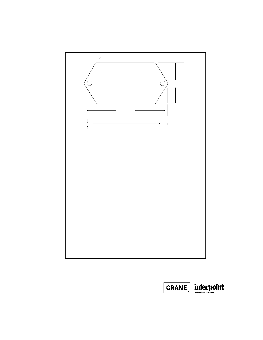
1.350 max
(34.29)
CAUTION
Heat from reflow or wave soldering may damage
the device. Solder pins individually with heat
application not exceeding 300
∞
C for 10 seconds
per pin.
Flange Thickness:
Cases J1 and J5
0.060 (1.52)
Case J2
0.073 (1.85) max
Cases J3 and J4
0.067 +0.005/-0.007 (1.70 +0.13/-0.8)
2.720 max
(69.09)
Dot on top of case indicates pin one
F
IGURE
35: C
ASE
J M
AXIMUM
D
IMENSIONS
Note: Although every effort has been made to render the case drawings at actual size, variations in the printing process may cause some distortion. Please refer
to the numerical dimensions for accuracy.

B8-25
CASE J
C
ASES
0.040 dia.
(1.02)
0.000
0.25 (6.4)
5
4
3
0.000
0.170
(4.32)
0.210
(5.33)
1.370
(34.80)
1.770
(44.96)
2.150
(54.61)
1
2
0.173
(4.39)
0.000
1.173
(29.79
0.673
(17.09)
0.162 dia
(4.11)
Flanged cases: Designator required in Case Option position of model number.
FMD28-461 EMI Filter (down-leaded): Screening ≠ Standard or ES
BOTTOM VIEW CASE J4 (Rev B)
Solder Seal
Solder Tip-off
0.505 max
(12.83)
Squared corner and dot on top
of case indicate pin one.
F
IGURE
39: C
ASE
J4

C2-10
TEST (125∞C Products)
STANDARD
/ES
/883 (Class H)*
PRE-CAP INSPECTION
Method 2017, 2032
yes
yes
yes
TEMPERATURE CYCLE (10 times)
Method 1010, Cond. C, -65∞C to 150∞C
no
no
yes
Method 1010, Cond. B, -55∞C to 125∞C
no
yes
no
CONSTANT ACCELERATION
Method 2001, 3000 g
no
no
yes
Method 2001, 500 g
no
yes
no
BURN-IN
Method 1015, 160 hours at 125∞C
no
no
yes
96 hours at 125∞C case (typical)
no
yes
no
FINAL ELECTRICAL TEST MIL-PRF-38534, Group A
Subgroups 1 through 6: -55∞C, +25∞C, +125∞C
no
no
yes
Subgroups 1 and 4: +25∞C case
yes
yes
no
HERMETICITY TESTING
Fine Leak, Method 1014, Cond. A
no
yes
yes
Gross Leak, Method 1014, Cond. C
no
yes
yes
Gross Leak, Dip (1 x 10
-3
)
yes
no
no
FINAL VISUAL INSPECTION
Method 2009
yes
yes
yes
Test methods are referenced to MIL-STD-883 as determined by MIL-PRF-38534.
*883 products are built with element evaluated components and are 100% tested and guaranteed over
the full military temperature range of ≠55∞C to +125∞C.
MOR Series
MFLHP Series
MFL Series
MHP Series
MTR Series
MQO Series**
MHD Series
MHV Series
MHF+ Series
MHF Series**
MGA Series
MSA Series
MGH Series
MCH Series
FM-704A EMI Filter
FMD**/FME EMI Filter
FMC EMI Filter
FMH EMI Filter
FMGA EMI Filter
FMSA EMI Filter
HUM Modules**
LCM Modules**
LIM Modules
QA SCREENING
125∞C PRODUCTS
125∞C P
RODUCTS
Applies to the following products
**MFLHP Series, MQO Series, MHF Series, FMD EMI Filters, Hum Modules, and LCM Modules do not offer
`883" screening.