B6-13
LIM SERIES
50 - 250 WATT
L
INE
I
NTERFACE
M
ODULE
40
TO
80 VDC I
NPUT
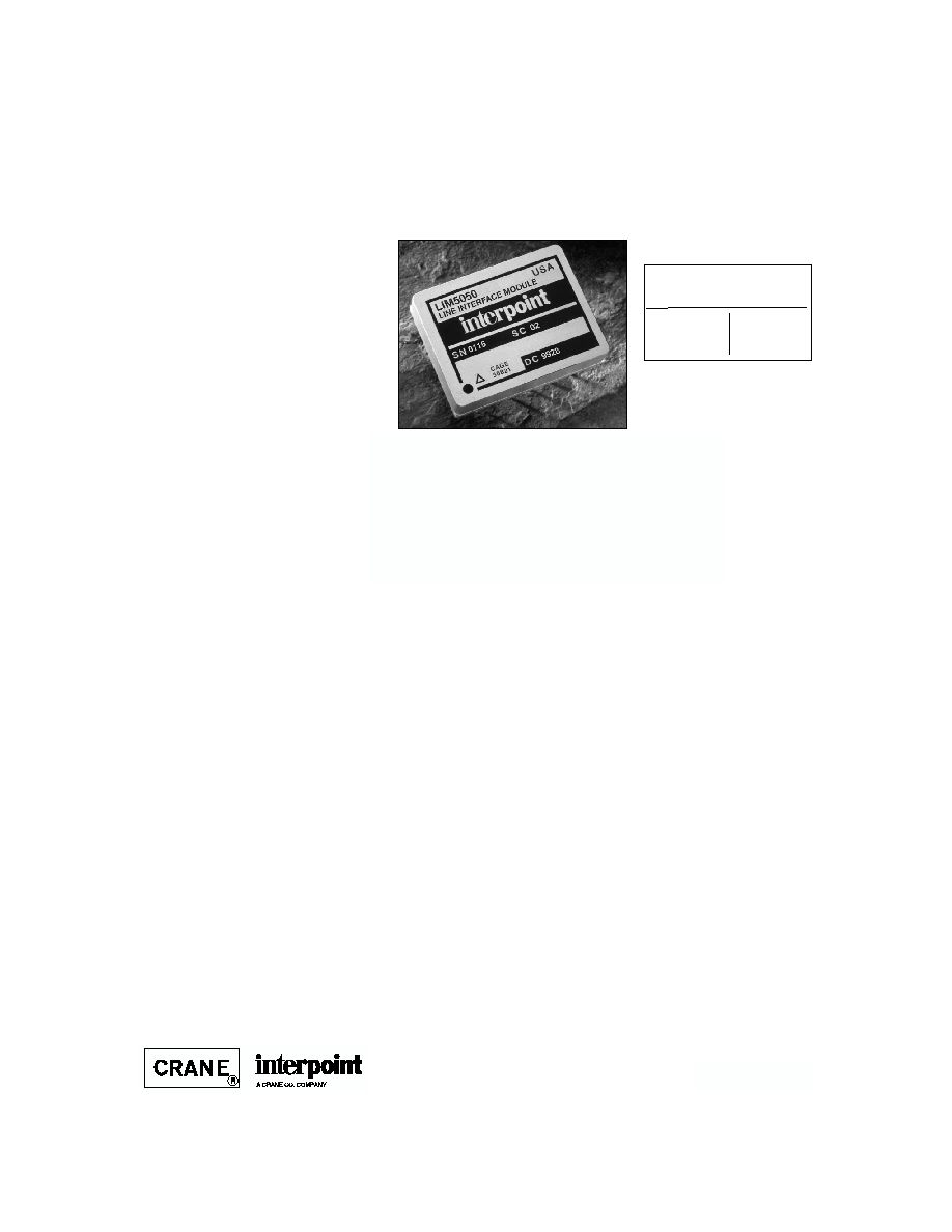
LIM5050
Size (max.): Non flanged
1.460 x 1.130 x 0.330 (37.08 x 28.70 x 8.38 mm)
Flanged
2.005 x 1.130 x 0.330 (50.93 x 28.70 x 8.38 mm)
See Section B8, cases E1 and G1, for dimensions.
Weight:
30 grams typical
Screening: Standard, ES, or 883
See Section C2 for screening options, see Section
A5 for ordering information.
F
EATURES
∑ -55∞C to +125∞C operation
∑ 40 to 80 VDC input
∑ Fixed frequency, 550 kHz typical
∑ Topology ≠ Non-isolated buck
∑ 35 VDC input with lowered efficiency
∑ Withstands transients of
up to 90 V for up to120 ms.
∑ 35 VDC output
∑ Inhibit function
∑ Power readiness function
∑ Load fault/short circuit protection
∑ Up to 94% efficiency, 90 W/in
3
MODEL
THROUGHPUT POWER
MODEL
LIM5050TM
LIM50250TM
WATTS
50
250
DESCRIPTION
The LIM50TM Series of line interface modules provide a nominal
output voltage of 35 VDC from input voltages of 45 to 75 VDC with
efficiencies of 94% or higher. Sustained operation at voltages as
high at 80 or as low as 35 are possible with reduced efficiency. The
LIM5050 module delivers 50 watts of output power over the full mili-
tary temperature range of ≠55∞C to +125∞C and fits in a package of
1.460 x 1.130 x 0.330 inches (37.08 x 28.70 x 8.38 mm) maximum,
resulting in a power density of 91 watts/in
3
.
S
CREENING
The LIM SeriesTM modules offer three screening options ≠ Standard,
ES, or 883. See Section C2, Screening, for descriptions.
C
ONVERTER
D
ESIGN
The LIM5050 modules are non-isolated converters operating at a
frequency between 500 kHz and 600 kHz. The control circuitry uses
average current mode control to achieve a wide bandwidth with little
or no overshoot over a wide range of loads. These converters are
specifically designed to accommodate loads with a negative imped-
ance such as those presented by Interpoint DC/DC converters with
a constant power consumption.
P
ARALLEL
O
PERATION
: U
P TO
10 M
ODULES
Up to 10 LIM Series modules can be paralleled for increased power.
Current sharing is typically within 2%.
O
VERLOAD AND
C
URRENT
L
IMIT
Current overload protection is accomplished by monitoring the
output current resulting in a constant current mode when the load
exceeds approximately 125% of rated load at full output voltage.
When the overload condition forces the output voltage to drop the
maximum current delivered falls from approximately 1.9 amps to
less than 1.5 amps. This feature keeps the short circuit dissipation
low and forces the output voltage to collapse rapidly thereby
preventing operation in an abnormal condition. Combined with the
"Power Ready" signal (see below), this foldback of the output
current prevents power cycling of the downstream converters.
P
OWER
R
EADY
S
IGNAL
To avoid high current surges during power up, the interface module
has a signal intended to connect to the inhibit lines of Interpoint
converters to keep these converters turned off until the interface
module's output exceeds approximately 13 volts thereby assuring
that, in an overload condition, the converters powered by the inter-
face module will shut off before the power ready signal turns them
off. This feature prevents repeated limit cycling in an overload condi-
tion.
I
NHIBIT
The LIM Series modules have an open collector TTL compatible
inhibit terminal that can be used to disable power conversion,
resulting in a very low quiescent input current and no generation of
switching noise.
Future offerings are planned for the LIM Series of modules.
Please contact your Interpoint representative listed in Section
A5, for more details.
B6-14
LIM SERIES
50 - 250 WATT
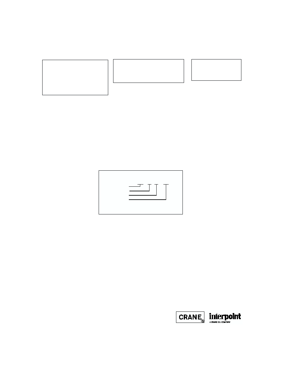
MODEL NUMBERING KEY
LIM 50 50 / 883
Base Model
Input Voltage
Output Power
Screening
(Standard screening has no designator
in this position.)
RECOMMENDED OPERATING CONDITIONS
ABSOLUTE MAXIMUM RATINGS
Input Voltage
∑ 40 to 72 VDC
Output Power
∑ 50 watts
Lead Soldering Temperature (10 sec per lead)
∑ 300∞C
Storage Temperature Range (Case)
∑ ≠65∞C to +150∞C
Input Voltage Range
∑ 40 to 72 VDC continuous
Case Operating Temperature (Tc)
∑ ≠55∞C to +125∞C full power
∑ ≠55∞C to +135∞C absolute
INHIBIT
Inhibit: TTL Open Collector
∑ Logic low (output disabled)
∑ Referenced to input common
∑ Logic high (output enabled)
287311-001-DTS Rev A
DQ# 3005
All technical information is believed to be accurate, but no responsibility is assumed for
errors or omissions. Interpoint reserves the right to make changes in products or specifi-
cations without notice. LIM Series, LIM5050, and LIM50250 are trademarks of Interpoint.
Copyright © 1999 Interpoint. All rights reserved.
L
INE
I
NTERFACE
M
ODULE
B8-10
CASE E
C
ASES
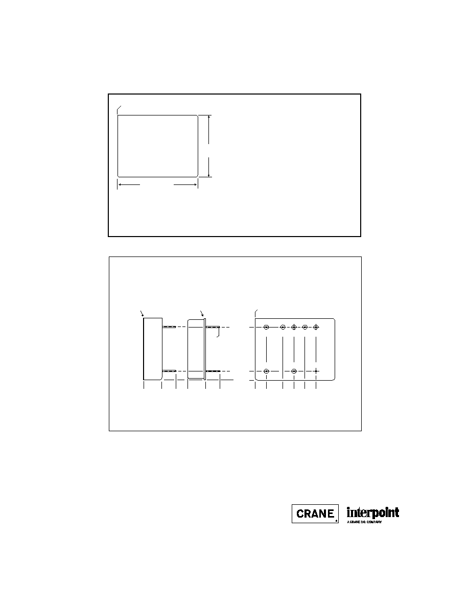
CASE E
BOTTOM VIEW
See Figures 16 ≠ 18
for pin configurations.
Squared corner and dot on top
of case indicate pin one.
1.460 max
(37.08)
1.130 max
(28.70)
Materials
Header Cold Rolled Steel/Nickel/Gold
Cover Kovar/Nickel
(SMHF Series
Cold Rolled Steel/Nickel/Gold)
Pins #52
alloy/Gold
compression glass seal
Case dimensions in inches (mm)
Tolerance
±
0.005 (0.13) for three decimal places
±
0.01 (0.3) for two decimal places
unless otherwise specified
CAUTION
Heat from reflow or wave soldering may damage
the device. Solder pins individually with heat
application not exceeding 300
∞
C for 10 seconds
per pin.
0.000
0.205
(5.21)
0.505
(12.83)
0.705
(17.91)
0.905
(22.99)
1.105
(28.07)
0.330 max
(8.38)
0.000
0.25 (6.35)
0.000
0.160
(4.06)
0.960
(24.38)
1
2
3
4
5
0.030 dia.
(0.76)
8
7
6
MHF+ Series Single and Dual: Screening ≠ Standard, ES, or 883
MHF Series and LIM5050 Module: Screening ≠ Standard or ES
SMHF Series Single and Dual and SLIM5050 Module:
Screening ≠ Space Standard, H, or K
HR120 Series: No screening options
BOTTOM VIEW CASE E1
0.330 max
(8.38)
0.000
0.25 (6.35)
Projection Weld
Seam Seal
Squared corner and dot on top
of case indicate pin one.
F
IGURE
16: C
ASE
E1
F
IGURE
15: C
ASE
E M
AXIMUM
D
IMENSIONS
Note: Although every effort has been made to render the case drawings at actual size, variations in the printing process may cause some distortion. Please refer
to the numerical dimensions for accuracy.

B8-15
CASE G
C
ASES
Materials
Header Cold Rolled Steel/Nickel/Gold
Cover
MHF+ Series and FMH Filter
Kovar/Nickel
SMHF
Cold Rolled Steel/Nickel
Pins
#52 alloy (all cases)
compression glass seal
Case dimensions in inches (mm)
Tolerance
±
0.005 (0.13) for three decimal places
±
0.01 (0.2) for two decimal places
unless otherwise specified
CASE G
BOTTOM VIEW
Flanged package
See Figures 25 - 27
for pin configuration
2.005 max
(50.93)
1.130 max
(28.70)
Squared corner and dot on top
of case indicate pin one.
CAUTION
Heat from reflow or wave soldering may damage
the device. Solder pins individually with heat
application not exceeding 300
∞
C for 10 seconds
per pin.
Flange Thickness: 0.047 (1.19)
1.590 (40.39)
0.128 dia
(3.25)
0.030 dia.
(0.76)
Flanged cases: Designator required in Case Option position of model number
MHF+ Series Single and Dual, LIM5050 Module: Screening ≠ Standard, ES, or 883
SMHF Series, SLIM5050 Module: Screening ≠ Space Standard, H, or K
BOTTOM VIEW CASE G1
0.000
0.205 (5.21)
0.505 (12.83)
0.705 (17.91)
0.905 (22.99)
1.105 (28.07)
0.000
0.160
(4.06)
0.960
(24.38)
1
2
3
4
5
8
7
6
0.140 (3.56)
0.560
(14.22)
0.330 max.
(8.38)
0.000
0.25 (6.35)
0.330 max.
(8.38)
0.000
0.25 (6.35)
Squared corner and dot on top
of case indicate pin one.
Projection Weld
Seam Seal
F
IGURE
25: C
ASE
G1
F
IGURE
24: C
ASE
G M
AXIMUM
D
IMENSIONS
Note: Although every effort has been made to render the case drawings at actual size, variations in the printing process may cause some distortion. Please refer
to the numerical dimensions for accuracy.
C2-10
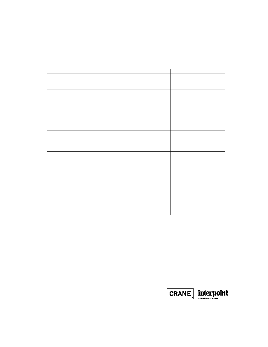
TEST (125∞C Products)
STANDARD
/ES
/883 (Class H)*
PRE-CAP INSPECTION
Method 2017, 2032
yes
yes
yes
TEMPERATURE CYCLE (10 times)
Method 1010, Cond. C, -65∞C to 150∞C
no
no
yes
Method 1010, Cond. B, -55∞C to 125∞C
no
yes
no
CONSTANT ACCELERATION
Method 2001, 3000 g
no
no
yes
Method 2001, 500 g
no
yes
no
BURN-IN
Method 1015, 160 hours at 125∞C
no
no
yes
96 hours at 125∞C case (typical)
no
yes
no
FINAL ELECTRICAL TEST MIL-PRF-38534, Group A
Subgroups 1 through 6: -55∞C, +25∞C, +125∞C
no
no
yes
Subgroups 1 and 4: +25∞C case
yes
yes
no
HERMETICITY TESTING
Fine Leak, Method 1014, Cond. A
no
yes
yes
Gross Leak, Method 1014, Cond. C
no
yes
yes
Gross Leak, Dip (1 x 10
-3
)
yes
no
no
FINAL VISUAL INSPECTION
Method 2009
yes
yes
yes
Test methods are referenced to MIL-STD-883 as determined by MIL-PRF-38534.
*883 products are built with element evaluated components and are 100% tested and guaranteed over
the full military temperature range of ≠55∞C to +125∞C.
MOR Series
MFLHP Series
MFL Series
MHP Series
MTR Series
MQO Series**
MHD Series
MHV Series
MHF+ Series
MHF Series**
MGA Series
MSA Series
MGH Series
MCH Series
FM-704A EMI Filter
FMD**/FME EMI Filter
FMC EMI Filter
FMH EMI Filter
FMGA EMI Filter
FMSA EMI Filter
HUM Modules**
LCM Modules**
LIM Modules
QA SCREENING
125∞C PRODUCTS
125∞C P
RODUCTS
Applies to the following products
**MFLHP Series, MQO Series, MHF Series, FMD EMI Filters, Hum Modules, and LCM Modules do not offer
`883" screening.