 | –≠–ª–µ–∫—Ç—Ä–æ–Ω–Ω—ã–π –∫–æ–º–ø–æ–Ω–µ–Ω—Ç: MDCB5D | –°–∫–∞—á–∞—Ç—å:  PDF PDF  ZIP ZIP |

VDC O
UTPUT
1
Size (max):MDCG-H 3.005 x 1.505 x 0.400 inches (76.33 x 38.23 x 10.16 mm)
MDCA-F 3.005 x 2.260 x 0.400 inches (76.33 x 57.40 x 10.16 mm)
Weight:
MDCG-H 100 grams maximum
MDCA-F 150 grams maximum
Screening: Standard or ES
Description
Interpoint's MDC SeriesTM of DC/DC converters offers a unique
product by effectively combining two, three, or four individual
modular DC/DC converters to provide more than one hundred
combinations. The modules are established high-reliability military
aerospace DC/DC converters with input voltages of 16 to 40 VDC
and a typical transient rating of 50 V for 50 milliseconds. All modules
operate from no-load to full load and provide a constant current limit
at each output.
Features
All converters have an inhibit function. Remote sense and trim up to
0.6V is available on the 30 watt single modules. The 15 watt and 30
watt choices have synchronization - if two are used, the synchro-
nization functions are combined internally.
M
ULTIPLE
O
UTPUT
(2-8),
F
ACTORY
C
ONFIGURABLE
DC/DC C
ONVERTERS
28 V
OLT
I
NPUT
MDC SERIES
UP TO 60 WATTS
F
EATURES
∑ ≠55∞ to +100∞C operation
∑ 16 to 40 VDC input
∑ Two to eight outputs
* Fully Isolated
∑ 50 V for up to 50 ms transient
protection
∑ Inhibit function
∑ Sync function available on
select modules
∑ Sense available on select
single output modules
∑ Short circuit protection
Mix or match volt-
ages and power to
configure from two
to eight outputs.
Table 1: Modules ≠ Power and Vout
Power
Vout
Features
30 Watt
3.3
Inhibit &
5
Sync &
12
Sense/
15
Trim up
18
±5
Inhibit &
±12
Sync
±15
15 Watt
3.3
Inhibit &
5
Sync
5.2
12
15
28
±5
±12
±15
Power
Vout
Features
5 Watt
5
Inhibit
5.2
12
15
±5
±12
±15
1.5 Watt
3.3
Inhibit
5
5.2
12
15
±5
±12
±15

2
MDC SERIES
UP TO 60 WATTS
F
ACTORY
C
ONFIGURABLE
DC/DC C
ONVERTERS
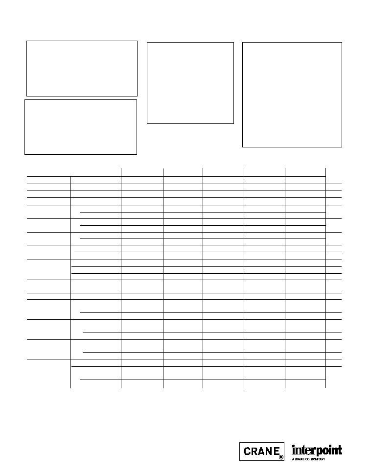
Table 2: Configurations
Case Size: 3. 005 x 1.505 x 0.400 inches (76.33 x 38.23 x 10.16 mm)
Configuration
Resulting
Module Power (Watts)
Selection Letter
2
Output Power (W)
30
15
5
1.5
G
30
0
2
0
0
H
8
0
0
1
2
Case Size: 3.005 x 2.260 x 0.400 inches (76.33 x 57.40 x 10.16 mm
Configuration
Resulting
Module Power (Watts)
Selection Letter
1
Output Power (W)
30
15
5
1.5
A
60
2
0
0
0
B
45
1
1
0
1
C
40
1
0
2
0
D
33
0
2
0
2
E
26
0
1
2
1
F
20
0
0
4
0
Selecting a configuration:
Begin with the base model letters - MDC. Add a
configuration letter from "Table 2: Configurations"
that matches the number of outputs and power
level you require. Using "Table 1: Modules" from
page 1, choose from the available voltages in the
power levels determined by the configuration letter.
Add the chosen voltages to the model and configu-
ration letters beginning with the highest wattage
down to the lowest.
As an example: To configure a four output, 45 watt,
converter begin with MDCB. Choose the output
voltages for the 30 watt, 15 watt, and 1.5 watt
modules in Table 2. For this example a 30 watt 5
volt dual output, a 15 watt 28 volt single output, and
a 1.5 watt 12 volt output were selected. The
resulting configuration is MDCB/05D/28S/12S.
More Examples:
MDCD/15D/12S/5S/5S
33 watt total, five outputs:
15 watt dual 15 volt, 15 watt single 12 volt, 1.5 watt
single 5 volt, 1.5 watt single 5 volt
MDCB/3.3S/5D/12D
45 watt total, five outputs: 30 watt single 3.3 volt, 15
watt dual 5 volt, 1.5 watt dual 12 volt
1. Case has eighteen pins which may limit the number of output voltages available.
2. Case has twelve pins which may limit the number of output voltages available.
Note: The specifications on the following pages are for the individual modules. The specifications/perform-
ance of the configured converter may vary from the specifications in the "Electrical Characteristics" tables.
Please contact the factory for details.
3
MDC SERIES
UP TO 60 WATTS
F
ACTORY
C
ONFIGURABLE
DC/DC C
ONVERTERS
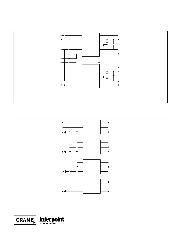
Block Diagrams: Examples of Configurations
Case Size: 3.005 x 2.260 x 0.400
+V1
Return 1
Inhibit 1
Vin
Return
+Sense 1
≠Sense 1
Sync 1
+V1
Return 1
Inhibit 2
+Sense 1
≠Sense 1
Sync 2
30 Watt
Vin
In Com
Inh
+V
Ret
Sync In
+S
≠S
30 Watt
Vin
In Com
Inh
+V
Ret
Sync In
+S
≠S
Case
+V1
Return 1
≠V1
Inhibit 1
+V2
Return 2
≠V2
Inhibit 2
+V3
Return 3
≠V3
Inhibit 3
+V4
Return 4
≠V4s
Inhibit 4
Vin
Return
Case Size: 3.005 x 2.260 x 0.400
5 Watt
Vin
Rtn
Inh
+V
Ret
≠V
5 Watt
Vin
Rtn
Inh
+V
Ret
≠V
5 Watt
Vin
Rtn
Inh
+V
Ret
≠V
5 Watt
Vin
Rtn
Inh
+V
Ret
≠V
Figure 1: MDCA ≠ 60 watts, 2 outputs
Figure 2: MDCF ≠ 20 watts, 8 outputs
4
MDC SERIES
UP TO 60 WATTS
F
ACTORY
C
ONFIGURABLE
DC/DC C
ONVERTERS
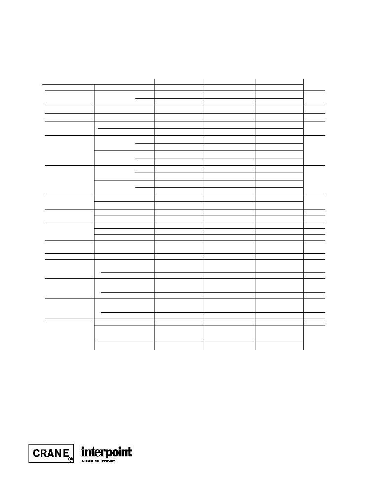
30 Watt Single Output Modules
SINGLE OUTPUT MODULES
3R3S
05S
12S
15S
18S
PARAMETER
CONDITION
MIN
TYP
MAX
MIN TYP MAX
MIN
TYP
MAX
MIN
TYP
MAX
MIN
TYP
MAX
UNITS
OUTPUT VOLTAGE
3.27
3.30
3.33
4.95
5.00
5.05 11.88 12.00 12.12 14.85 15.00 15.15 17.82 18.00 18.18
VDC
OUTPUT CURRENT
1
V
IN
= 16 to 40 VDC
0
≠≠
6.06
0
--
5.0
0
--
2.5
0
--
2.0
0
--
1.67
A
OUTPUT POWER
1
V
IN
= 16 to 40 VDC
0
--
20
0
--
25
0
--
30
0
--
30
0
--
30
W
OUTPUT RIPPLE
10 kHz ≠ 2 MHz
--
15
40
--
35
50
--
25
50
--
25
50
--
--
40
mV p-p
VOLTAGE
Tc = ≠55∞C TO +125∞C
--
--
50
--
50
90
--
40
90
--
40
90
--
--
90
LINE REGULATION
2
Vin = 16 to 40 VDC
--
5
10
--
10
30
--
10
30
--
10
30
--
--
30
mV
Tc = ≠55∞C TO +125∞C
--
--
10
--
15
50
--
15
50
--
15
50
--
--
50
LOAD REGULATION
NO LOAD TO FULL
--
2
10
--
5
30
--
5
30
--
5
30
--
--
30
mV
Tc = ≠55∞C TO +125∞C
--
--
10
--
15
50
--
15
50
--
15
50
--
--
50
INPUT VOLTAGE
1
CONTINUOUS
16
28
40
16
28
40
16
28
40
16
28
40
16
28
40
VDC
NO LOAD TO FULL
TRANSIENT 50 ms
--
--
50
--
--
50
--
--
50
--
--
50
--
--
50
V
INPUT CURRENT
1
NO LOAD
--
30
75
--
35
75
--
35
75
--
35
75
--
--
50
mA
FULL LOAD
--
0.94
--
--
1.15
--
--
1.30
--
--
1.25
--
--
1.33
--
A
INHIBITED
--
7
8
--
3
8
--
3
8
--
3
8
--
--
8
mA
INPUT RIPPLE
10 kHz ≠ 10 MHz
CURRENT
Tc = ≠55∞C TO +125∞C
--
25
50
--
20
50
--
20
50
--
20
50
--
--
50
mA p-p
EFFICIENCY
74
76
--
76
78
--
80
83
--
81
84
--
81
--
--
%
LOAD FAULT
3
SHORT CIRCUIT
POWER DISSIPATION
--
--
10
--
--
10
--
--
10
--
--
10
--
--
10
W
RECOVERY
1, 4
--
1.4
6
--
1.4
5
--
1.4
5
--
1.4
5
--
1.4
--
ms
STEP LOAD RESP.
50% ≠ 100% ≠ 50%
TRANSIENT
--
±125
±250
--
±200 ±300
--
±250 ±400
--
±350 ±500
--
--
±600
mV pk
RECOVERY
4
--
--
200
--
60
200
--
60
200
--
60
200
--
60
--
µs
STEP LINE RESP.
16 ≠ 40 ≠ 16 VDC
TRANSIENT
5
--
--
±300
--
±200 ±300
--
±400 ±500
--
±500 ±600
--
±500
--
mV pk
RECOVERY
4
--
--
300
--
--
300
--
--
300
--
--
300
--
300
--
µs
START-UP
1
DELAY
--
1.4
5
--
1.4
5
--
1.4
5
--
1.4
5
--
--
5
ms
OVERSHOOT
FULL LOAD
--
0
50
--
0
50
--
0
120
--
0
150
--
0
--
mV pk
NO LOAD
--
33
150
--
50
250
--
120
600
--
150
750
--
--
--
TYPICAL CHARACTERISTICS
SYNC AND INHIBIT
RECOMMENDED OPERATING CONDITIONS
ABSOLUTE MAXIMUM RATINGS
Input Voltage
∑ 16 to 40 VDC
Output Power
∑ 25 to 30 watts depending on model
Lead Soldering Temperature (10 sec per pin)
∑ 300∞C
Storage Temperature Range (Case)
∑ ≠65∞C to +135∞C
Output Voltage Temperature Coefficient
∑ 100 ppm/∞C typical single and dual outputs
∑ 200 ppm/∞C main, 300 ppm/∞C aux
triple output
Input to Output Capacitance
∑ 50 pF typ. (100 pF typ triple outputs)
Current Limit
∑ 115% of full load typical
Isolation
∑ 100 megohm minimum at 500 V
Audio Rejection
∑ 40 dB typ (50 dB typ triple output)l
Conversion Frequency
∑ Free run 550 min, 600 typ, 650 max kHz
∑ External sync 500 to 675 kHz
Inhibit Pin Voltage (unit enabled)
∑ 9 to 11 V
Input Voltage Range
∑ 16 to 40 VDC continuous
∑ 50 V for 50 msec transient
Case Operating Temperature (Tc)
∑ ≠55∞C to +100∞C full power
∑ ≠55∞C to +115∞C absolute
Derating Output Power/Current
∑ Linearly from 100% at 100∞C to 0% at 115∞C
Electrical Characteristics: 25∞C Tc, 28 VDC Vin, 100% load, free run, unless otherwise specified.
Sync (500 to 675 kHz)
∑ Duty cycle 40% min, 60% max
∑ Logic low 0.8 V max
∑ Logic high 4.5 V min, 5 V max
∑ Referenced to input common
∑ If not used, connect to input common
Inhibit TTL Open Collector
∑ Logic low (output disabled)
Voltage
0.8 V
Inhibit pin current 8.0 mA max
∑ Referenced to input common
∑ Logic high (output enabled)
Open collector
Notes
1. Tc = ≠55∞C to +100∞C
2. Operation is limited below 16V.
3. Indefinite short circuit protection not guaranteed above 100∞C case.
4. Recovery time is measured from application of the transient to point at which
Vout is within 1% of final value.
5. Transition time
10 µs.
5
MDC SERIES
UP TO 60 WATTS
F
ACTORY
C
ONFIGURABLE
DC/DC C
ONVERTERS
30 Watt Dual Output Modules
DUAL OUTPUT MODULES
05D
12D
15D
PARAMETER
CONDITIONS
MIN TYP MAX
MIN
TYP
MAX
MIN
TYP
MAX
UNITS
OUTPUT VOLTAGE
+V
OUT
4.95
5.00
5.05
11.88
12.00
12.12 14.85
15.00
15.15
VDC
≠V
OUT
4.92
5.00
5.07
11.82
12.00
12.18
14.77
15.00
15.23
OUTPUT CURRENT
1, 2
V
IN
= 16 TO 40 VDC
0
2.5
4.5
0
1.25
2.25
0
1.0
1.8
A
OUTPUT POWER
1, 2
V
IN
= 16 TO 40 VDC
0
--
25
0
--
30
0
--
30
W
OUTPUT RIPPLE
10 kHz - 2 MHz
--
20
50
--
30
80
--
25
80
mV p-p
VOLTAGE +/≠ V
OUT
Tc = ≠55∞C TO +125∞C
--
40
80
--
40
120
--
40
120
LINE REGULATION
3
+V
OUT
--
10
50
--
10
30
--
10
30
V
IN
= 16 TO 40 VDC
≠V
OUT
--
50
100
--
50
120
--
50
150
mV
Tc = ≠55∞C +V
OUT
--
10
50
--
10
50
--
10
50
TO +125∞C
≠V
OUT
--
50
100
--
50
150
--
50
180
LOAD REGULATION
+V
OUT
--
5
30
--
15
30
--
15
30
NO LOAD TO FULL
≠V
OUT
--
25
50
--
30
120
--
30
150
mV
Tc = ≠55∞C
+V
OUT
--
5
50
--
15
50
--
15
50
TO +125∞C
≠V
OUT
--
25
100
--
30
180
--
30
180
CROSS REGULATION
SEE NOTE 4
--
7
12
--
4
8.3
--
3
8
%
EFFECT ON ≠V
OUT
SEE NOTE 5
--
4
6
--
4
6
--
4
6
INPUT VOLTAGE
1
CONTINUOUS
16
28
40
16
28
40
16
28
40
VDC
NO LOAD TO FULL
TRANSIENT 50 ms
0
--
50
0
--
50
0
--
50
V
INPUT CURRENT
NO LOAD
--
35
75
--
50
75
--
50
75
mA
FULL LOAD
--
1.10
--
--
1.34
--
--
1.29
--
A
INHIBITED
--
3
8
--
3
8
--
3
8
mA
INPUT RIPPLE
CURRENT
1
10 kHz - 10 MHz
--
15
50
--
20
50
--
20
50
mA p-p
EFFICIENCY
76
78
--
78
81
--
80
83
--
%
LOAD FAULT
6
POWER DISSIPATION
SHORT CIRCUIT
1
--
--
10
--
--
10
--
--
10
W
RECOVERY
--
1.4
5.0
--
1.4
5.0
--
1.4
5.0
ms
STEP LOAD 50
≠ 100 ≠ 50% BALANCED
RESPONSE ± V
OUT
TRANSIENT
--
±200
±300
--
±150
±300
--
±200
±400
mV pk
RECOVERY
7
--
100
200
--
100
200
--
100
200
µs
STEP LINE
16 ≠ 40 ≠ 16 V
IN
RESPONSE ± V
OUT
TRANSIENT
8
--
±200
±400
--
±200
±400
--
±400
±500
mV pk
RECOVERY
7
--
--
300
--
--
300
--
--
300
µs
START≠UP
1
DELAY
--
1.4
5
--
1.4
5
--
1.4
5
ms
OVERSHOOT
FULL LOAD
--
0
50
--
0
120
--
0
150
mV pk
NO LOAD
--
50
250
--
120
600
--
150
750
Electrical Characteristics: 25∞C Tc, 28 VDC Vin, 100% load, free run, unless otherwise specified.
Notes
1.Tc = ≠55∞C to +100∞C.
2. Up to 90% of the total output current/power is available from either output
providing the positive output is carrying at least 10% of the total output
power.
3. Operation is limited below 16 V (see Figure 21).
+P
out
20% to 80%; ≠P
out
80% to 20%
5. Effect on the negative output under the following conditions:
+P
out
50%; ≠P
out
10% to 50%
6. Indefinite short circuit protection not guaranteed above 100∞C case.
7. Recovery time is measured from application of the transient to point at which
Vout is within 1% of final value.
8. Transition time
10 µs.