
MODEL
B1-12
EMI I
NPUT
F
ILTER
120 V
OLT
I
NPUT
SFME120-461
EMI FILTER 2.1
AMP
DESCRIPTION
The SFME120-461TM EMI filter modules are specifically designed to
reduce the reflected input ripple current of Interpoint's high
frequency DC/DC converters. SFME120-461 filters minimize elec-
tromagnetic interference (EMI) for Interpoint's SMHP120 Series of
converters. These filters are intended for use in 120 volt applica-
tions which must meet MIL-STD-461 levels of conducted emis-
sions. One filter can be used with multiple converters up to the rated
throughput current of the filter.
S
CREENING AND
R
EPORTS
The SFME120-461 filter offers three screening options ≠ Standard,
Class H, or Class K. See Section C2, Quality Assurance, pages C2-
7 through C2-9, for descriptions. Detailed reports on product
performance are also available and are listed on page C2-9.
I
NPUT
R
IPPLE AND
EMI
Switching DC/DC converters naturally generate two noise compo-
nents on the power input line: differential noise and common mode
noise. Input ripple current refers to both of these components.
Differential noise occurs between the positive input and input
common. Most Interpoint converters have an input filter that reduces
differential noise which is sufficient for most applications.
Common mode noise occurs across stray capacitances between
the converter's power train components and the baseplate (bottom
of the package) of the converter.
Where low noise currents are required to meet CE03 of MIL-STD-
461, a power line filter is needed. The SFME120-461 EMI power line
filter reduces the common mode and differential noise generated by
the converters. SFME120-461 filters reduce input ripple current by
as much as 60 dB at 500 kHz and 55 dB at 1 MHz when used in
conjunction with Interpoint's DC/DC converters.
The filter must be placed as close as possible to the converter for
optimum performance. The baseplates of the filter and the converter
should be connected with the shortest and widest possible conduc-
tors. For the best connection, mount the filter's and converter's
baseplates on or above a small ground plane.
O
PERATION OVER
T
EMPERATURE
SFME120-461 filters are rated for full power operation from ≠55∞C
to +125∞C case temperature. Current is derated linearly to zero at
+135∞C case temperature.
I
NSERTION
L
OSS
The maximum dc insertion loss at full load and nominal input voltage
represents a power loss of less than 4%.
P
ACKAGING
SFME120-461 filters are sealed in metal hermetic side-leaded pack-
ages (see Section B8, cases U2, V, W, Y, and Z). Additionally the
FMD28-461 filter is available in a metal hermetic down-leaded
package (see Section B8, case J4).
For more information, contact your Interpoint representative
listed in Section A5.
F
EATURES
∑ Fully qualified to Class H or K
∑ Passive components for
maximum tolerance in space
environments
∑ ≠55∞ to +125∞C operation
∑ 120 volt input
∑ Up to 2.1 amps of
throughput current
∑ Up to 60 dB attenuation
at 500 kHz.
∑ Compliant to
MIL-STD-461C, CE03
∑ Compatible with
MIL-STD-704E
DC power bus
Size (max.): 3.005 x 1.505 x 0.400 inches (76.33 x 38.23 x 10.16mm)
See Section B8, case U1, for dimensions.
Weight:
110 grams maximum
Screening:
Standard, Class H, or Class K (MIL-PRF-38534)
See Section C2 for screening options, see Section A5 for
ordering information.
SFME120-461
2.1 amp
All technical information is believed to be accurate, but no responsibility is assumed
for errors or omissions. Interpoint reserves the right to make changes in products
or specifications without notice. SFME120-461 is a trademark of Interpoint.
Copyright © 1999 Interpoint. All rights reserved.
B8-36
CASE
CASE U
C
ASES
Materials
Header Cold Rolled Steel/Nickel/Gold
Cover
Kovar/Nickel
Pins #52
alloy/Gold
compression glass seal
Case dimensions in inches (mm)
Tolerance
±
0.005 (0.13) for three decimal places
±
0.01 (0.2) for two decimal places
unless otherwise specified
CAUTION
Heat from reflow or wave soldering may damage
the device. Solder pins individually with heat
application not exceeding 300
∞
C for 10 seconds
per pin.
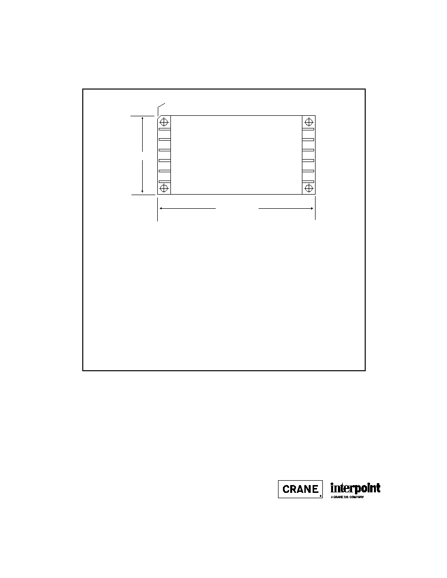
CASE U
TOP VIEW
(PIN SIDE)
See Figures 55 and 56 for dimensions
1.505 max (38.23)
3.005 (76.33) max.
Note: Pins are shown for Case U1.
Angled corner indicates pin one
F
IGURE
54: C
ASE
U M
AXIMUM
D
IMENSIONS
B8-37
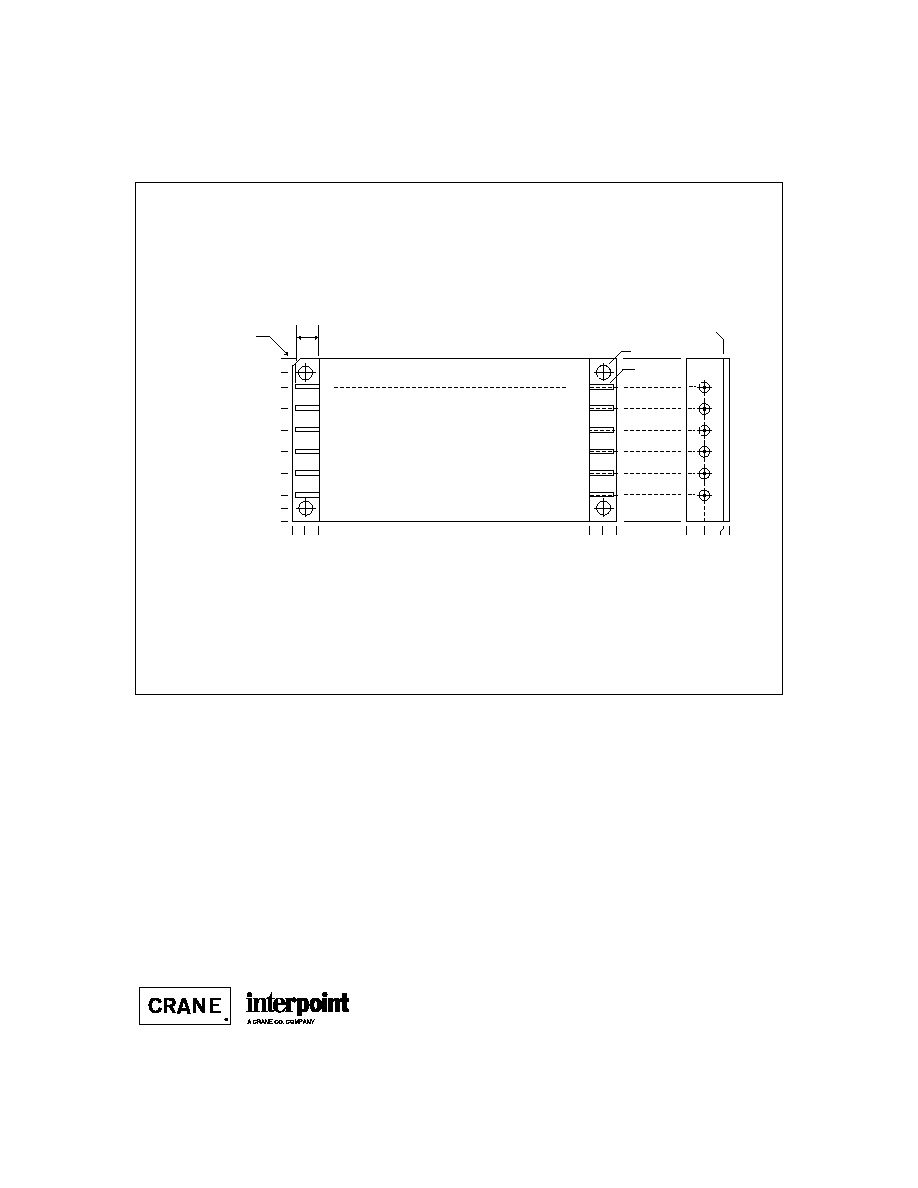
CASE U
C
ASES
Angled corner
indicates pin one.
1
2
3
4
5
6
12
11
10
9
8
7
0.000
0.050 (1.27)
0.000
0.120 (3.05)
0.250 (6.35)
0.450 (11.43)
0.650 (16.51)
0.850 (21.59)
1.050 (26.67)
1.250 (31.75)
1.380 (35.05)
1.505 (38.23) max.
0.000
0.120 (3.05)
0.250 (6.35)
2.750 (69.85)
2.880 (73.15)
3.005 (76.33) max.
0.128 dia
(3.25).
0.040 dia
(1.02)
0.23 (5.8) Lead Length
0.400 (10.16)
max.
0.220 (5.59
TOP VIEW CASE U1
MFL Series and MHP Series: Screening ≠ Standard, ES or 883
MFLHP Series, FMD270 EMI Filter, and FMD28-461SL EMI Filters:
Screening ≠ Standard or ES
SMFL, SMFLHP, SMHP, and SSP Series; SFCS, and SFME EMI Filters:
Screening ≠ Standard, Class H or K
HUM70 Module and LCM Module: Screening ≠ Standard or ES
Seam Seal
F
IGURE
55: C
ASE
U1

C2-7
QA SCREENING
SPACE PRODUCTS
S
PACE
P
RODUCTS
E
LEMENT
E
VALUATION
S
TANDARD
C
LASS
C
LASS
T
EST
P
ERFORMED
(O)
H
K
(
COMPONENT LEVEL
)
M/S
P
M/S
P
M/S
P
Element Electrical
yes
no
yes
yes
yes
yes
Element Visual
no
no
yes
yes
yes
yes
Internal Visual
no
no
yes
no
yes
no
Temperature Cycling
no
no
no
no
yes
yes
Constant Acceleration
no
no
no
no
yes
yes
Interim Electrical
no
no
no
no
yes
no
Burn-in
no
no
no
no
yes
no
Post Burn-in Electrical
no
no
no
no
yes
no
Steady State Life
no
no
no
no
yes
no
Voltage Conditioning /Aging
no
no
no
no
no
yes
Visual Inspection
no
no
no
no
no
yes
Final Electrical
no
no
yes
yes
yes
yes
Wire Bond Evaluation
*
no
no
yes
yes
yes
yes
SEM
no
no
no
no
yes
no
SLAMTM/C-SAM:
Input capacitors only
no
no
no
yes
no
yes
(Add'l test, not req. by H or K)
Definitions
Element Evaluation: Component testing/screening per MIL-STD-883 as determined by MIL-PRF-38534
SEM: Scanning Electron Microscopy
SLAMTM: Scanning Laser Acoustic Microscopy
C-SAM: C - Mode Scanning Acoustic Microscopy
Notes
M/S
Active components (Microcircuit and Semiconductor Die)
P
Passive components
*
Not applicable to EMI filters that have no wirebonds
SMFLHP Series
SMFL Series
SMHP Series (O&H only)
SMTR Series
SSP Series
SMHF Series
SMSA Series
SLH Series
SLIM Module
SFME120 EMI Filter
SFME28 EMI Filter
SFCS EMI Filter
SFMC EMI Filter
STF EMI Filter
Applies to the following products:
C2-8
QA SCREENING
SPACE PRODUCTS
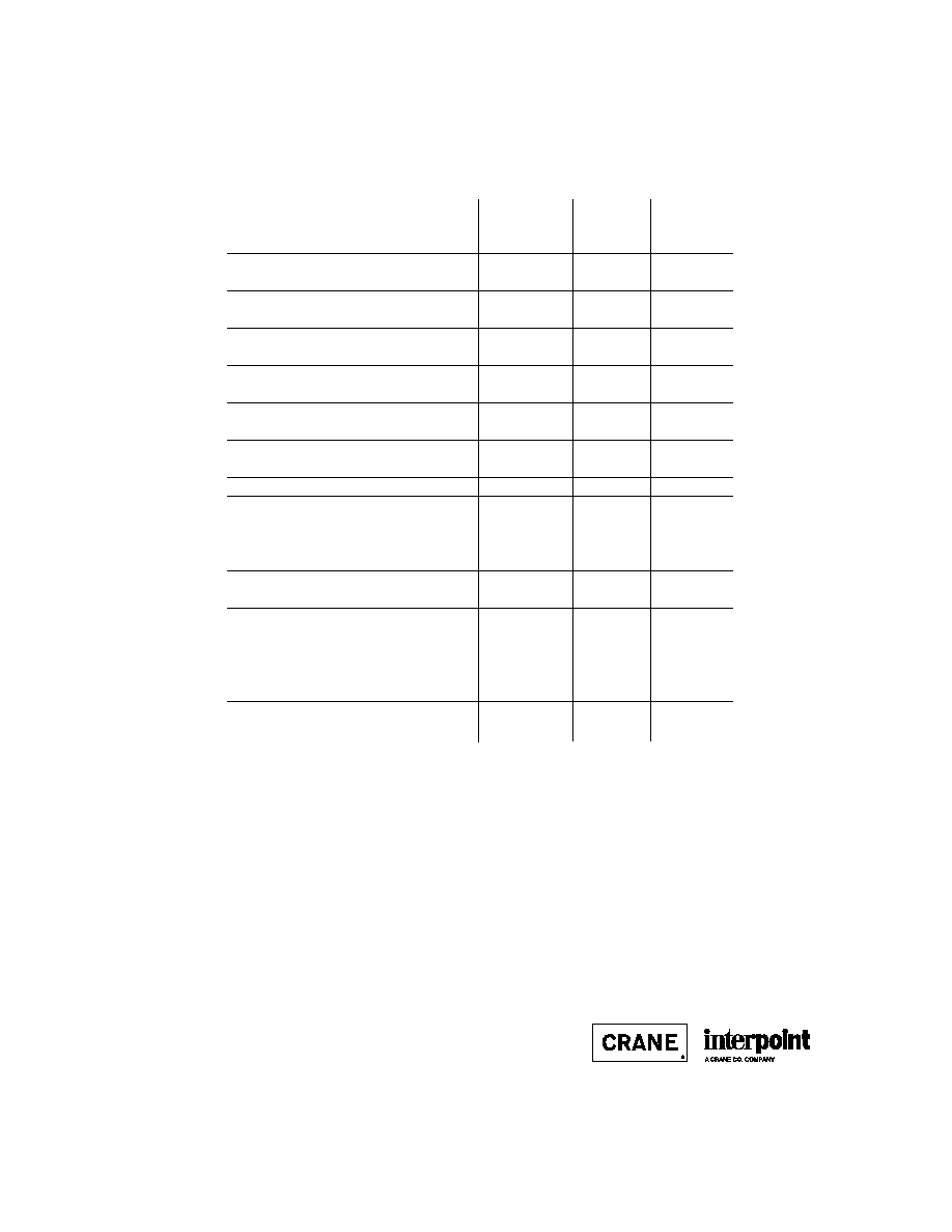
E
NVIRONMENTAL
S
CREENING
T
EST
P
ERFORMED
S
TANDARD
C
LASS
C
LASS
(
END ITEM LEVEL
)
(O)
H
K
Non-destruct bond pull*
Method 2023
no
no
yes
Pre-cap inspection
Method 2017, 2032
yes
yes
yes
Temperature cycle
Method 1010, Cond. C
yes
yes
yes
Constant acceleration
Method 2001, 3000 g
yes
yes
yes
PIND Test
Method 2020, Cond. B
no
no
yes
Radiography
Method 2012
no
no
yes
Pre burn-in test
yes
yes
yes
Burn-in, Method 1015, 125∞C
96 hours
yes
no
no
160 hours
no
yes
no
2 x 160 hour (includes mid BI test)
no
no
yes
Final electrical test
MIL-PRF-38534, Group A
yes
yes
yes
Hermeticity test
Fine Leak,
Method 1014, Cond. A
yes
yes
yes
Gross Leak,
Method 1014, Cond. C
yes
yes
yes
Final visual inspection
Method 2009
yes
yes
yes
Test methods are referenced to MIL-STD-883 as determined by MIL-PRF-38534.
Note
* Not applicable to EMI filters that have no wirebonds.
SMFLHP Series
SMFL Series
SMHP Series (O&H only)
SMTR Series
SSP Series
SMHF Series
SMSA Series
SLH Series
SLIM Module
SFME120 EMI Filter
SFME28 EMI Filter
SFCS EMI Filter
SFMC EMI Filter
STF EMI Filter
Applies to the following products: