 | –≠–ª–µ–∫—Ç—Ä–æ–Ω–Ω—ã–π –∫–æ–º–ø–æ–Ω–µ–Ω—Ç: CA3059 | –°–∫–∞—á–∞—Ç—å:  PDF PDF  ZIP ZIP |
3
Æ
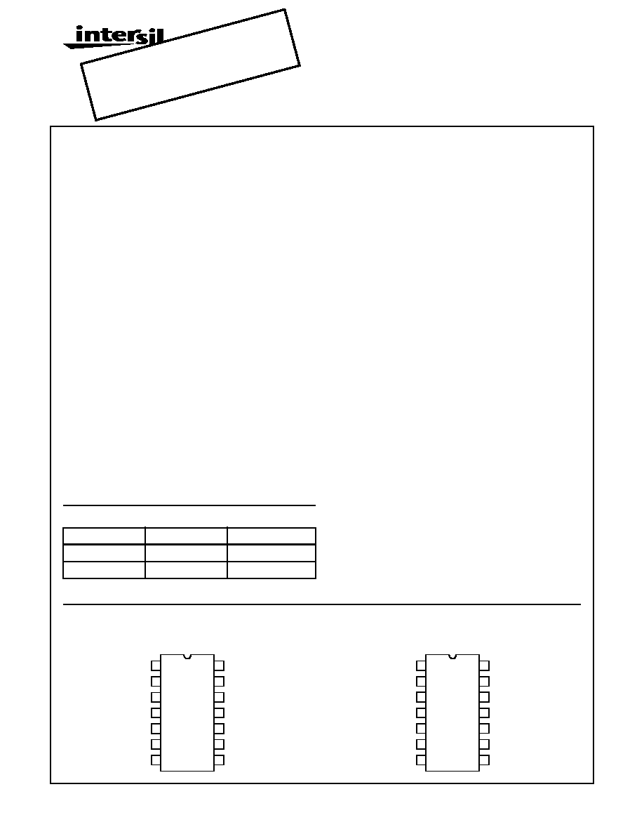
CA3059, CA3079
Zero-Voltage Switches for 50Hz-60Hz and
400Hz Thyristor Control Applications
Description
The CA3059 and CA3079 zero-voltage switches are mono-
lithic silicon integrated circuits designed to control a thyristor
in a variety of AC power switching applications for AC input
voltages of 24V, 120V, 208/230V, and 277V at 50Hz-60Hz
and 400Hz. Each of the zero-voltage switches incorporates
4 functional blocks (see the Functional Block Diagram) as
follows:
1. Limiter-Power Supply - Permits operation directly from an
AC line.
2. Differential On/Off Sensing Amplifier - Tests the condition
of external sensors or command signals. Hysteresis or
proportional-control capability may easily be implement-
ed in this section.
3. Zero-Crossing Detector - Synchronizes the output pulses
of the circuit at the time when the AC cycle is at zero volt-
age point; thereby eliminating radio-frequency interfer-
ence (RFI) when used with resistive loads.
4. Triac Gating Circuit - Provides high-current pulses to the
gate of the power controlling thyristor.
In addition, the CA3059 provides the following important
auxiliary functions (see the Functional Block Diagram).
1. A built-in protection circuit that may be actuated to remove
drive from the triac if the sensor opens or shorts.
2. Thyristor firing may be inhibited through the action of an
internal diode gate connected to Terminal 1.
3. High-power dc comparator operation is provided by over-
riding the action of the zero-crossing detector. This is ac-
complished by connecting Terminal 12 to Terminal 7.
Gate current to the thyristor is continuous when Terminal
13 is positive with respect to Terminal 9.
The CA3059 and CA3079 are supplied in 14 lead dual-in-
line plastic packages.
Features
∑ Relay Control
∑ Valve Control
∑ Synchronous Switching of Flashing Lights
∑ On-Off Motor Switching
∑ Differential Comparator with Self-Contained Power
Supply for Industrial Applications
∑ Photosensitive Control
∑ Power One-Shot Control
∑ Heater Control
∑ Lamp Control
Type Features
CA3059 CA3079
∑ 24V, 120V, 208/230V, 277V at 50/60 . . .
or 400Hz Operation
X
X
∑ Differential Input . . . . . . . . . . . . . . . . . .
X
X
∑ Low Balance Input Current (Max) -
µA. . .
1
2
∑ Built-In Protection Circuit for . . . . . . . .
Opened or Shorted Sensor (Term 14)
X
X
∑ Sensor Range (Rx) - k
. . . . . . . . . . . . . 2 - 100 2 - 50
∑ DC Mode (Term 12) . . . . . . . . . . . . . . . .
X
∑ External Trigger (Term 6) . . . . . . . . . . .
X
∑ External Inhibit (Term 1) . . . . . . . . . . . .
X
∑ DC Supply Volts (Max) . . . . . . . . . . . . .
14
10
∑ Operating Temperature Range (
o
C) . . .
-55 to +125
Ordering Information
PART NUMBER
TEMPERATURE
PACKAGE
CA3059
-55
o
C to +125
o
C
14 Lead Plastic DIP
CA3079
-55
o
C to +125
o
C
14 Lead Plastic DIP
FN490.5
Oct 1999
Pinouts
CA3059 (PDIP)
TOP VIEW
CA3079 (PDIP)
TOP VIEW
1
2
3
4
5
6
7
14
13
12
11
10
9
8
FAIL-SAFE
SENSE AMP IN
ZCD OVERRIDE
R DRIVER (COM)
SENSE AMP REF
COMMON
R DRIVER V
+
INHIBIT
DC SUPPLY
TRIGGER OUT
AC IN
TRIGGER IN
COMMON
HIGH CURRENT
NEG. TRIGGER
1
2
3
4
5
6
7
14
13
12
11
10
9
8
SENSE AMP IN
R DRIVER (COM)
SENSE AMP REF
COMMON
DO NOT USE
DO NOT USE
R DRIVER V
+
DC SUPPLY
TRIGGER OUT
AC IN
COMMON
HIGH CURRENT
NEG. TRIGGER
DO NOT USE
DO NOT USE
OBS
OLET
E PR
ODUC
T
NO R
ECOM
MEN
DED
REPL
ACEM
ENT
our T
echn
ical S
uppo
rt Ce
nter
at
1-888
-INTE
RSIL
or w
ww.in
tersil
.com
/tsc
CAUTION: These devices are sensitive to electrostatic discharge; follow proper IC Handling Procedures.
1-888-INTERSIL or 321-724-7143
|
Intersil (and design) is a trademark of Intersil Americas Inc.
Copyright © Intersil Americas Inc. 2002. All Rights Reserved

4
CA3059, CA3079
Functional Block Diagram
FIGURE 1. SCHEMATIC DIAGRAM OF CA3059 AND CA3079
AC INPUT VOLTAGE (50/60 OR 400Hz)
V AC
INPUT SERIES RESISTOR (R
S
)
k
DISSIPATION RATING FOR R
S
W
24
2
0.5
120
10
2
208/230
20
4
277
25
5
NOTE: Circuitry within shaded areas, not included in CA3079
See chart
IC = Internal connection - DO NOT USE (Terminal restriction applies only to CA3079)
EXTERNAL
INHIBIT
* NTC SENSOR
IC
R
P
R
X
R
S
100
µF
15V
+
-
9
10
11
6
R
L
CURRENT
BOOST
MT
2
MT
1
IC
IC
INHIBIT
G
* NEGATIVE TEMPERATURE COEFFICIENT
"0"
CROSSING
DET.
TRIAC
GATING
CIRCUIT
4
3
ON/OFF
SENSING
AMPL.
7
8
13
14
PROTECTION
CIRCUIT
1
2
12
LIMITER
5
AC INPUT
VOLTAGE
POWER
SUPPLY
All resistance values are in
NOTE: Circuitry within shaded areas
not included in CA3079
IC = Internal connection - DO NOT USE (Terminal restriction applies only to
FAIL-SAFE INPUT
TO
COMMON
INHIBIT
INPUT
FOR
EXTERNAL
TRIGGER
COMMON
R
SENSOR
R
P
R
4
10K
R
3
12K
R
7
10K
R
2
27K
13
C
F
100
µF
15V
COMMON
2
12
1
7
14
10
9
11
8
R
5
9.6K
Q
3
Q
2
Q
4
Q
5
TO
COMMON
R
6
15K
R
9
25
R
8
15
3
4
Q
8
Q
9
Q
7
Q
6
Q
10
D
9
D
8
D
12
D
15
D
10
D
11
R
10
40K
D
7
D
13
D
2
D
1
R
1
5K
5
R
S
AC
LINE
INPUT
6
TO
THYRISTOR
GATE
FOR
INCREASED
GATE DRIVE
IC
IC
IC
IC
Q
1
D
3
D
6
D
5
D
4
FOR DC MODE
OR 400Hz
OPERATION
5
Specifications CA3059, CA3079
Absolute Maximum Ratings
T
A
= +25
o
C
Thermal Information
DC Supply Voltage (Between Terminals 2 & 7)
CA3059. . . . . . . . . . . . . . . . . . . . . . . . . . . . . . . . . . . . . . . . . . 14V
CA3079. . . . . . . . . . . . . . . . . . . . . . . . . . . . . . . . . . . . . . . . . . 10V
DC Supply Voltage (Between Terminals 2 & 8)
CA3059. . . . . . . . . . . . . . . . . . . . . . . . . . . . . . . . . . . . . . . . . . 14V
CA3079. . . . . . . . . . . . . . . . . . . . . . . . . . . . . . . . . . . . . . . . . . 10V
Peak Supply Current (Terminals 5 & 7)
. . . . . . . . . . . . . . . . . . .±50mA
Output Pulse Current (Terminal 4) . . . . . . . . . . . . . . . . . . . . . 150mA
Thermal Resistance
JA
PDIP Package . . . . . . . . . . . . . . . . . . . . . . . . . . . . . . . . 100
o
C/W
Power Dissipation
Up to T
A
= +55
o
C CA3059, CA3079 . . . . . . . . . . . . . . . . . 950mW
Above T
A
= +55
o
C CA3059, CA3079 . . Derate Linearly 10mW/
o
C
Ambient Temperature
Operating. . . . . . . . . . . . . . . . . . . . . . . . . . . . . . . -55
o
C to +125
o
C
Storage . . . . . . . . . . . . . . . . . . . . . . . . . . . . . . . . -65
o
C to +150
o
C
Lead Temperature (During Soldering) . . . . . . . . . . . . . . . . . +265
o
C
At distance 1/16"
± 1/32" (1.59 ± 0.79) from case
for 10 seconds max
CAUTION: Stresses above those listed in "Absolute Maximum Ratings" may cause permanent damage to the device. This is a stress only rating and operation
of the device at these or any other conditions above those indicated in the operational sections of this specification is not implied.
Electrical Specifications
T
A
= +25
o
C, For all Types, Unless Otherwise Specified. All voltages are measured with respect to
Terminal 7. For Operating at 120V
RMS
, 50-60Hz (AC Line Voltage) (Note 1)
PARAMETERS
SYMBOL
TEST CONDITIONS
MIN
TYP
MAX
UNITS
DC SUPPLY VOLTAGE (Figure 2A, 2B, 2C)
Inhibit Mode
At 50/60Hz
V
S
R
S
= 8k
, I
L
= 0
6.1
6.5
7
V
At 400Hz
R
S
= 10k
, I
L
= 0
-
6.8
-
V
At 50/60Hz
R
S
= 5k
, I
L
= 0
-
6.4
-
V
Pulse Mode
At 50/60Hz
V
S
R
S
= 8k
, I
L
= 0
6
6.4
7
V
At 400Hz
R
S
= 10k
, I
L
= 0
-
6.7
-
V
At 50/60Hz
R
S
= 5k
, I
L
= 0
-
6.3
-
V
Gate Trigger Current (Figures 3, 4A)
I
GT
Terminal 4
Terminals 3 and 2 Connected,
V
GT
= 1V
-
105
-
mA
PEAK OUTPUT CURRENT (PULSED) (Figures 4, 5)
With Internal Power Supply
Figure 4a, 4b
I
OM
Terminal 4
Terminal 3 open, Gate Trigger
Voltage (V
GT
) = 0
50
84
-
mA
Terminals 3 and 2 Connected, Gate
Trigger Voltage (V
GT
) = 0
90
124
-
mA
With External Power Supply
Figure 5a, 5b, 5c
I
OM
Terminal 4
Terminal 3 open, V+ = 12V, V
GT
= 0
-
170
-
mA
Terminals 3 and 2 Connected,
V+ = 12V, V
GT
= 0
240
-
mA
Inhibit Input Ratio (Figure 6)
V
9
/V
2
Voltage Ratio of Terminals 9 to 2
0.465
0.485
0.520
-
TOTAL GATE PULSE DURATION (Note 2) (Figure 7A, 7B, 7C, 7D)
For Positive dv/dt
50-60Hz
t
P
C
EXT
= 0
70
100
140
µs
400Hz
C
EXT
= 0, R
EXT
=
-
12
-
µs
For Negative dv/dt
50-60Hz
t
N
C
EXT
= 0
70
100
140
µs
400Hz
C
EXT
= 0, R
EXT
=
-
10
-
µs
PULSE DURATION AFTER ZERO CROSSING (50-60Hz) (Figure 7A)
For Positive dv/dt
t
P1
C
EXT
= 0, R
EXT
=
-
50
-
µs
For Negative dv/dt
t
N1
-
60
-
µs
OUTPUT LEAKAGE CURRENT (Figure 8)
Inhibit Mode
I
4
-
0.001
10
µA
INPUT BIAS CURRENT (Figure 9)
CA3059
I
I
-
220
1000
nA
CA3079
-
220
2000
nA
Common-mode Input Voltage Range
V
CMR
Terminals 9 and 13 Connected
-
1.5 to
5
-
V
6
Specifications CA3059, CA3079
SENSITIVITY (Note 3) (Figures 4(a), 11)
Pulse Mode
V
13
Terminal 12 open
-
6
-
mV
NOTES:
1. The values given in the Electrical Characteristics Chart at 120V also apply for operation at input voltages of 208/230V, and 277V, except
for Pulse Duration. However, the series resistor (R
S
) must have the indicated value, shown in the chart in the Functional Block Diagram,
for the specified input voltage.
2. Pulse Duration in 50Hz applications is approximately 15% longer than shown in Figure 7(b).
3. Required voltage change at Terminal 13 to either turn OFF the triac when ON or turn ON the triac when OFF.
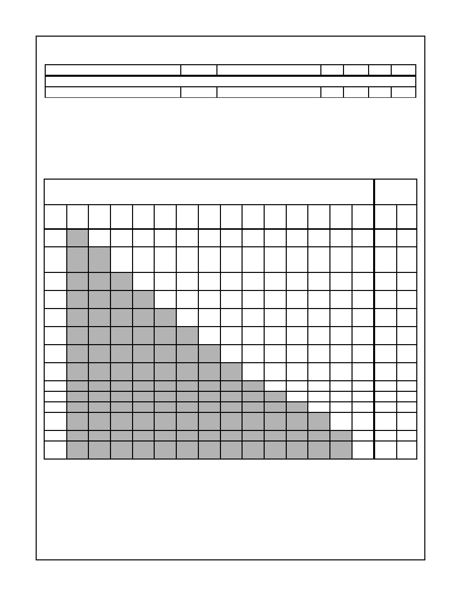
Maximum Voltage Ratings
T
A
= +25
o
C
MAXIMUM VOLTAGE RATINGS T
A
= +25
o
C
MAXIMUM
CURRENT
RATINGS
TERM.
NO.
NOTE 3
1
2
3
4
NOTE 1
5
NOTE 3
6
7
8
9
10
11
NOTE 3
12
13
NOTES
2, 3
14
I
IN
mA
I
OUT
mA
1
Note 3
Note 4 Note 4 Note 4 Note 4
15
0
10
-2
Note 4 Note 4 Note 4 Note 4 Note 4 Note 4 Note 4
10
0.1
2
0
-15
0
-15
2
-14
0
-14
0
Note 5
-14
0
Note 5
-14
0
-14
0
-14
0
-14
Note 4
0
-14
0
-14
150
10
3
0
-15
Note 4 Note 4 Note 4 Note 4 Note 4 Note 4 Note 4 Note 4 Note 4 Note 4 Note 4 Note 4
4
Note 4
2
-10
Note 4 Note 4 Note 4 Note 4 Note 4 Note 4 Note 4 Note 4
0.1
150
5
Note 1
Note 4
7
-7
Note 4 Note 4 Note 4 Note 4 Note 4 Note 4 Note 4
50
10
6
Note 3
14
0
Note 4 Note 4 Note 4 Note 4 Note 4 Note 4 Note 4 Note 4 Note 4
7
Note 4
14
0
Note 4
20
0
2.5
-2.5
14
0
6
-6
Note 4 Note 4
8
10
0
Note 4 Note 4 Note 4 Note 4 Note 4
0.1
2
9
Note 4 Note 4 Note 4 Note 4 Note 4 Note 4 Note 4
10
Note 4 Note 4 Note 4 Note 4 Note 4 Note4
11
Note 4 Note 4 Note 4 Note 4 Note4
12
Note 3
Note 4 Note 4
50
50
13
Note 4 Note 4 Note4
14
Note 3
2
2
This chart gives the range of voltages which can be applied to the terminals listed horizontally with respect to the terminals listed vertically.
For example, the voltage range of horizontal Terminal 6 to vertical Terminal 4 is 2V to -10V.
NOTES:
1. Resistance should be inserted between Terminal 5 and external supply or line voltage for limiting current into Terminal 5 to less than
50mA.
2. Resistance should be inserted between Terminal 14 and external supply for limiting current into Terminal 14 to less than 2mA.
3. For the CA3079 indicated terminal is internally connected and, therefore, should not be used.
4. Voltages are not normally applied between these terminals; however, voltages appearing between these terminals are safe, if the spec-
ified voltage limits between all other terminals are not exceeded.
5. For CA3079 (0V to -10V).
Electrical Specifications
T
A
= +25
o
C, For all Types, Unless Otherwise Specified. All voltages are measured with respect to
Terminal 7. For Operating at 120V
RMS
, 50-60Hz (AC Line Voltage) (Note 1)
(Continued)
PARAMETERS
SYMBOL
TEST CONDITIONS
MIN
TYP
MAX
UNITS

7
CA3059, CA3079
FIGURE 2A. DC SUPPLY VOLTAGE TEST CIRCUIT FOR CA3059
AND CA3079
FIGURE 2B. DC SUPPLY VOLTAGE vs AMBIENT TEMPERA-
TURE FOR CA3059 AND CA3079
FIGURE 2C. DC SUPPLY VOLTAGE vs EXTERNAL LOAD
CURRENT FOR CA3059 AND CA3079
FIGURE 3. GATE TRIGGER CURRENT vs GATE TRIGGER
VOLTAGE FOR CA3059 AND CA3079
FIGURE 4A. PEAK OUTPUT (PULSED) AND GATE TRIGGER
CURRENT WITH INTERNAL POWER SUPPLY
TEST CIRCUIT FOR CA3059 AND CA3079
FIGURE 4B. PEAK OUTPUT CURRENT (PULSED) vs AMBIENT
TEMPERATURE FOR CA3059 AND CA3079
2
13
5
7
PULSE
4.6K
CA3059
CA3079
AC LINE
R
S
8
4
9
10
11
INHIBIT
0.3K
4.6K
I
L
V
S
R
L
100
µF
EXTERNAL
LOAD
CURRENT
ALL RESISTANCE
VALUES ARE IN
7.00
6.75
6.50
6.25
6.00
5.75
INT
E
RNAL
DC S
U
P
P
L
Y
(
V
)
-75
-50
-25
0
25
50
75
100
125
AMBIENT TEMPERATURE (
o
C)
120VRMS, 50/60Hz OPERATION
INPUT RESISTANCE (R
S
) = 10k
NO EXTERNAL LOAD
INHIBIT MODE
PULSE MODE
INT
E
RNAL
DC S
U
P
P
L
Y
(
V
)
6.5
6.0
5.5
5.0
4.5
4.0
3.5
0
1
2
3
4
5
6
7
8
EXTERNAL LOAD CURRENT (mA)
120VRMS, 50/60Hz OPERATION
T
A
= +25
o
C
R
S
= 5k
(INHIBIT
MODE)
R
S
= 5k
(PULSE
MODE)
R
S
= 10k
(INHIBIT
MODE)
R
S
= 10k
(PULSE
MODE)
G
A
T
E
T
R
IG
G
E
R CUR
RE
NT
(
m
A)
0
1
2
3
130
120
110
100
90
80
70
60
50
40
GATE TRIGGER (V)
TERMINAL 3 OPEN
TERMINALS 2 AND 3
CONNECTED
120VRMS, 50/60Hz OPERATION
T
A
= +25
o
C
CA3059
CA3079
9
10
11
5
7
4
2
3
13
8
R
S
10K
AC LINE
OSCILLOSCOPE
WITH
HIGH GAIN
INPUT
V
GT
100
µF
6K
5K
1
±1%
I
OM
(4)
OR
I
GT
(4)
AMBIENT TEMPERATURE (
o
C)
-75
-50
-25
0
25
50
75
100 125
150
125
100
75
50
P
E
AK O
U
T
P
UT
CURRE
NT
, P
U
L
S
E
D
(
m
A)
120VRMS, 50/60Hz OPERATION
GATE TRIGGER, V
GT
= 0 (V)
TERMINALS 2 AND 3
CONNECTED
TERMINAL 3 OPEN
175