 | –≠–ª–µ–∫—Ç—Ä–æ–Ω–Ω—ã–π –∫–æ–º–ø–æ–Ω–µ–Ω—Ç: CA3189 | –°–∫–∞—á–∞—Ç—å:  PDF PDF  ZIP ZIP |

1
May 1999
CA3189
FM IF System
Features
∑ Includes IF Amplifier, Quadrature Detector, AF
Preamplifier, and Specific Circuits for AGC, AFC, Tun-
ing Meter, Deviation-Noise Muting, and ON Channel
Detector
∑ FM IF Amplifier Applications in High-Fidelity,
Automotive, and Communications Receivers
∑ Exceptional Limiting Sensitivity -12
µ
V (Typ) at -3dB
Point
∑ Low Distortion -0.1% (Typ) (with Double-Tuned Coil)
∑ Single-Coil Tuning Capability
∑ Improved S + N/N Ratio
∑ Externally Programmable Recovered Audio Level
∑ Provides Specific Signal for Control of Interchannel
Muting (Squelch)
∑ Provides Specific Signal for Direct Drive of a Tuning
Meter
∑ On Channel Step for Search Control
∑ Provides Programmable AGC Voltage for RF Amplifier
∑ Provides a Specific Circuit for Flexible Audio Output
∑ Internal Supply Voltage Regulators
∑ Externally Programmable "On" Channel Step Width,
and Deviation at Which Muting Occurs
Description
The Harris CA3189E is a monolithic integrated circuit that
provides all the functions of a comprehensive FM-lF system.
The block diagram of the CA3189E includes a three-stage
FM-lF amplifier/limiter configuration with level detectors for
each stage, a doubly-balanced quadrature FM detector and
an audio amplifier that features the optional use of a muting
(squelch) circuit.
The advanced circuit design of the IF system includes desir-
able deluxe features such as programmable delayed AGC
for the RF tuner, an AFC drive circuit, and an output signal to
drive a tuning meter and/or provide stereo switching logic. In
addition, internal power-supply regulators maintain a nearly
constant current drain over the voltage supply range of
+8.5V to +16V.
The CA3189E is ideal for high-fidelity operation. Distortion in
a CA3189E FM-lF System is primarily a function of the
phase linearity characteristic of the outboard detector coil.
The CA3189E has all the features of the CA3089E plus addi-
tions. See CA3189E features compared to the CA3089E in
Table 1.
Pinout
CA3189
(PDIP)
TOP VIEW
Part Number Information
PART NUMBER
TEMP.
RANGE (
o
C)
PACKAGE
PKG.
NO.
CA3189E
-40 to 85
16 Ld PDIP
E16.3
14
15
16
9
13
12
11
10
1
2
3
4
5
7
6
8
IF IN
INPUT
FRAME
MUTE CONTROL
AUDIO OUT
IF OUT
AFC OUT
DELAYED AGC
SUBSTRATE (GND)
TUNING
MUTE LOGIC
V+
REF BIAS
QUADRATURE
BYPASS
METER OUT
INPUT
CAUTION: These devices are sensitive to electrostatic discharge. Users should follow proper IC Handling Procedures.
1-800-4-HARRIS or 407-727-9207
|
Copyright
©
Harris Corporation 1999
File Number
1046.4
[ /Title
(CA31
89)
/Sub-
ject
(FM
IF Sys-
tem)
/Autho
r ()
/Key-
words
(Har-
ris
Semi-
con-
ductor,
FM IF
ampli-
fier,
quadrat
ure
detec-
tor,
tuning
meter
out-
put,
lim-
iter,
AFC
circuit,
AGC
cir-
cuit,
mut-
ing cir-
cuit,
indus-
trial
tem-
pera-
OBSOLETE PR
ODUCT
POSSIBLE SUBSTITUTE PR
ODUCT
CA3089E

2
Absolute Maximum Ratings
Thermal Information
DC Supply Voltage
(Between Terminals 11 and 4) . . . . . . . . . . . . . . . . . . . . . . . . 16V
(Between Terminals 11 and 14) . . . . . . . . . . . . . . . . . . . . . . . 16V
DC Current (Out of Terminal 15) . . . . . . . . . . . . . . . . . . . . . . . . 2mA
Operating Conditions
Temperature Range . . . . . . . . . . . . . . . . . . . . . . . . . -40
o
C to 85
o
C
Thermal Resistance (Typical, Note 1)
JA
(
o
C/W)
PDIP Package . . . . . . . . . . . . . . . . . . . . . . . . . . . . .
90
Maximum Junction Temperature (Plastic Package) . . . . . . . . 150
o
C
Maximum Storage Temperature Range . . . . . . . . . -65
o
C to 150
o
C
Maximum Lead Temperature (Soldering 10s) . . . . . . . . . . . . 300
o
C
CAUTION: Stresses above those listed in "Absolute Maximum Ratings" may cause permanent damage to the device. This is a stress only rating and operation
of the device at these or any other conditions above those indicated in the operational sections of this specification is not implied.
NOTE:
1.
JA
is measured with the component mounted on an evaluation PC board in free air.
Electrical Specifications
T
A
= 25
o
C, V+ = 12V
PARAMETER
SYMBOL
TEST CONDITIONS
CIRCUIT
OR FIG.
NO.
MIN
TYP
MAX
UNITS
DC SPECIFICATIONS
Quiescent Circuit Current
I
11
No Signal Input, Non Muted
1, 2
20
31
40
mA
DC Voltages
No Signal Input, Non Muted
Terminal 1 (IF Input)
V
1
1, 2
1.2
1.9
2.4
V
Terminal 2 (AC Return to Input)
V
2
1, 2
1.2
1.9
2.4
V
Terminal 3 (DC Bias to Input)
V
3
1, 2
1.2
1.9
2.4
V
Terminal 15 (RF AGC)
V
15
1, 2
7.5
9.5
11
V
Terminal 10 (DC Reference)
V
10
1, 2
5
5.6
6
V
DYNAMIC SPECIFICATIONS
Input Limiting Voltage (-3dB Point)
V
I
(lim)
f
O
= 10.7MHz,
f
MOD
. = 400Hz,
Deviation
±
75kHz
1, 2
-
12
25
µ
V
AM Rejection (Terminal 6)
AMR
V
IN
= 0.1V,
AM Mod. = 30%
1, 2
45
55
-
dB
Recovered AF Voltage (Terminal 6)
V
O
(AF)
1, 2
325
500
650
mV
Total Harmonic Distortion (Note 2)
Single Tuned (Terminal 6)
THD
V
IN
= 0.1V
1
-
0.5
1
%
Double Tuned (Terminal 6)
THD
2
-
0.1
-
%
Signal Plus Noise to Noise Ratio
(Terminal 6)
S + N/N
V
IN
= 0.1V
1, 2
65
72
-
dB
Deviation Mute Frequency
f
DEV
f
MOD
= 0
1, 5, 6
-
±
40
-
kHz
RF AGC Threshold
V
16
1, 2
-
1.25
-
V
On Channel Step
V
12
V
IN
= 0.1V
f
DEV
<
±
40kHz
1
-
0
-
V
f
DEV
>
±
40kHz
1
-
5.6
-
V
NOTE:
2. THD characteristics are essentially a function of the phase characteristics of the network connected between Terminals 8, 9, and 10.
CA3189

3
TABLE 1.
CA3189E FEATURES COMPARED TO CA3089E
FEATURES
CA3189E
CA3089E
Low Limiting Sensitivity (12
µ
V Typ)
Yes
Yes
Low Distortion
Yes
Yes
Single-Coil Tuning Capability
Yes
Yes
Programmable Audio Level
Yes
No
S/N Mute
Yes
Yes
Deviation Mute
Yes
No
Flexible AFC
Yes
Yes
Programmable AGC Threshold and Voltage
Yes
No
Typical S + N/N > 70 dB
Yes
No
Meter Drive Voltage Depressed at Very Low Signal Levels
Yes
No
On-Channel Step Control Voltage
Yes
No
Test Circuits
NOTES:
3. All resistance values are in ohms.
4. L tunes with 100pF (C) at 10.7MHz. Q
0
(unloaded)
75 (TOKO No.
KACS K586HM or equivalent).
5. C = 0.01
µ
F for 50
µ
s deemphasis (Europe).
C = 0.015
µ
F for 75
µ
s deemphasis (USA).
FIGURE 1. TEST CIRCUIT FOR CA3189E USING A SINGLE-
TUNED DETECTOR COIL
NOTES:
6. All resistance values are in ohms.
7. T: PRI. - Q
0
(unloaded)
75 (tunes with 100pF (C
1
) 20
of 34e on
7
/
32
" dia. form. SEC. - Q
0
(unloaded)
75 (tunes with 100pF (C
2
)
20
of 34e on
7
/
32
" dia. form. kQ (percent of critical coupling)
70% (Adjusted for coil voltage (V
C
) = 150mV).
8. Above values permit proper operation of mute (squelch) circuit
"E" type slugs, spacing 4mm.
9. C = 0.01
µ
F for 50
µ
s deemphasis (Europe) C = 0.015
µ
F for 75
µ
s
deemphasis (USA).
FIGURE 2. TEST CIRCUIT FOR CA3189E USING A DOUBLE-
TUNED DETECTOR COIL
AUDIO
OUT
SIGNAL
INPUT
VOLTAGE
14
4
15
13
5
12
0.01
µ
F
10
K
33K
0.01
µ
F
C
6
FULL
SCALE
150
µ
A
2
3
0.01
µ
F
0.33
µ
F
10K
470
TUNING METER
0.02
µ
F
51
1
0.01
µ
F
11
0.05
µ
F
8
7
9
3.9K
100
C
L
8.2K
22
µ
H
AFC
V+ = 12V
pF
CA3189E
16
OUT
10
5K
10
µ
F
10
µ
F
TO
PIN 13
47K
22K
1
µ
F
(NOTE
4)
(NOTE
5)
SIGNAL
INPUT
VOLTAGE
14
4
15
13
0.01
µ
F
10
K
33K
0.01
µ
F
FULL
SCALE
150
µ
A
2
3
0.01
µ
F
TUNING METER
0.02
µ
F
51
1
0.01
µ
F
11
0.05
µ
F
8
9
8.2K
100
C
2
T (NOTE 7)
22
µ
H
V+ = 12V
pF
C
1
100
pF
3K
AUDIO
OUT
5
12
C
6
0.33
µ
F
10K
470
7
8.2K
AFC
OUT
10
5K
10
µ
F
10
µ
F
22K
1
µ
F
16
TO
PIN 13
47K
CA3189E
(NOTE 9)
CA3189
4
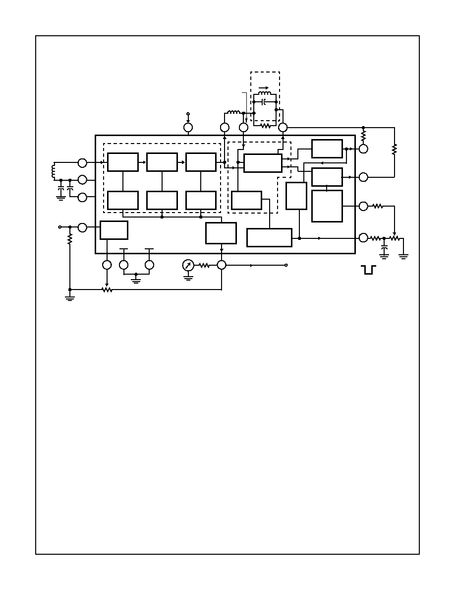
Block Diagram
NOTES:
10. All resistance values are in
.
11. L Tunes with 100pF (C) at 10.7MHz. Q
O
75 (TOKO No. KACS K586HM or equivalent).
14
13
15
2
3
1
8
9
5
6
7
4
LEVEL
DETECTOR
12
LEVEL
DETECTOR
LEVEL
DETECTOR
LEVEL
DETECTOR
1
ST
IF
AMPL.
2
ND
IF
AMPL.
3
RD
IF
AMPL.
MUTE (SQUELCH)
DRIVE CIRCUIT
QUADRATURE
DETECTOR
TUNING
METER
CIRCUIT
AFC
AMPL.
AUDIO
AMPL.
AUDIO
MUTE
(SQUELCH)
CONTROL
AMPL.
FRAME SUBSTRATE
150
µ
A
METER
33K
TUNING METER OUTPUT
TO STEREO
THRESHOLD
LOGIC CIRCUITS
10K
DELAYED
AGC FOR
RF AMPL
0.02
µ
F
0.02
µ
F
IF
INPUT
TO INTERNAL
REGULATORS
OUT
REFERENCE
BIAS
AFC
OUTPUT
AUDIO
OUTPUT
MUTING
SENSITIVITY
0.33
µ
F
10K
470
QUADRATURE
INPUT
22
µ
H
C =
100pF
L
IF AMPLIFIER
ON CHANNEL
INDICATOR
8.2K
5K
FM
DETECTOR
22K
DEVI-
ATION
MUTE
LOGIC
DELAYED
RF AGC
16
47K
CA3189E
11
V+
10
(NOTE 11)
CA3189

5
Schematic Diagrams
V+
V+
Q
14
Q
14A
Q
16
Q
17
Q
13A
R
16A
2.2K
R
15A
2.2K
R
15
2.8K
R
17
533
R
16
2.8K
Q
18
Q
13
C
11
1
C
12
1
C
13
1
C
14
1
R
6
2K
R
7
2K
R
11
2K
R
10
2K
A
B
Q
3
Q
4
Q
1
Q
2
Q
6
R
3
533
R
2
2.8K
INPUT
BYPASSING
1
2
3
IF
INPUT
IF AMPLIFIER
C
Q
9
Q
15
R
19
2K
R
18
2K
R
23
2K
R
24
500
R
25
1.52K
R
27
750
V+
Q
21
Q
22
C
B
A
R
20
2K
R
28
750
Q
20
R
21
500
R
22
1.52
K
D
E
V+
R
60
424
R
59
212
Q
74
Q
75
Q
77
Q
84
R
61A
1.1K
D
1
TUNING
METER
13
Q
68
Q
69
R
62
5K
R
61
4K
Q
76
C
8
3
R
56
600
Q
64
Q
63
C
7
3
R
53
600
Q
70
Q
62
Q
61
C
6
3
Q
60
R
52
400
Q
59
C
5
2
R
51
5K
V+
R
82
15.6K
Q
108
Q
105
Q
106
D
8
R
81
1.28K
R
83
500
R
84
1K
880
Q
107
16
15
AGC FOR
RF AMPL.
R
1
2.8K
Q
8
Q
8A
Q
10
Q
11
Q
7A
R
13A
2.1K
R
12A
2.1K
R
12
2.1K
R
14
533
R
13
2.1K
Q
12
Q
7
LEVEL DETECTOR AND METER CIRCUIT
F
Q
19
R
80
4.12K
CA3189