1
Æ
FN7174.2
EL4584
Horizontal Genlock, 4F
SC
The EL4584 is a PLL (Phase Lock Loop) sub system,
designed for video applications but also suitable for general
purpose use up to 36MHz. In video applications, this device
generates a TTL/CMOS compatible Pixel Clock (CLK OUT)
which is a multiple of the TV horizontal scan rate and phase
locked to it.
The reference signal is a horizontal sync signal, TTL/CMOS
format, which can be easily derived from an analog
composite video signal with the EL4583 Sync Separator. An
input signal to "coast" is provided for applications were
periodic disturbances are present in the reference video
timing such as VTR head switching. The Lock detector
output indicates correct lock.
The divider ratio is four ratios for NTSC and four similar
ratios for the PAL video timing standards, by external
selection of three control pins. These four ratios have been
selected for common video applications including 4F
SC
,
3F
SC
, 13.5MHz (CCIR 601 format) and square picture
elements used in some workstation graphics. To generate
8F
SC
, 6F
SC
, 27MHz (CCIR 601 format) etc. use the
EL4585, which includes an additional divide-by-two stage.
For applications where these frequencies are inappropriate
or for general purpose PLL applications the internal divider
can be bypassed and an external divider chain used.
Features
∑ 36MHz, general purpose PLL
∑ 4F
SC
based timing (use the EL4585 for 8F
SC
)
∑ Compatible with EL4583 sync separator
∑ VCXO, Xtal, or LC tank oscillator
∑ < 2ns jitter (VCXO)
∑ User controlled PLL capture and lock
∑ Compatible with NTSC and PAL TV formats
∑ 8 pre-programmed TV scan rate clock divisors
∑ Selectable external divide for custom ratios
∑ Single 5V, low current operation
∑ Pb-Free plus anneal available (RoHS compliant)
Applications
∑ Pixel clock regeneration
∑ Video compression engine (MPEG) clock generator
∑ Video capture or digitization
∑ PIP (Picture in Picture) timing generator
∑ Text or graphics overlay timing
Demo Board
A demo PCB is available for this product.
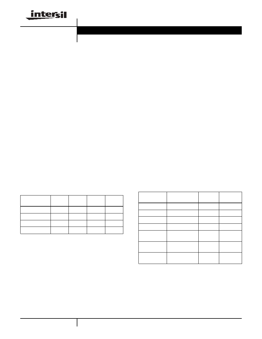
FREQUENCIES AND DIVISORS
FUNCTION
3F
SC
(NOTE 1)
CCIR 601
(NOTE 2)
SQUARE
(NOTE 3)
4F
SC
Divisor
851
864
944
1135
PAL F
OSC
(MHz)
13.301
13.5
14.75
17.734
Divisor
682
858
780
910
NTSC F
OSC
MHz)
10.738
13.5
12.273
14.318
NOTES:
1. 3F
SC
numbers do not yield integer divisors.
2. CCIR 601 Divisors yield 720 pixels in the portion of each line for
NTSC and PAL.
3. Square pixels format gives 640 pixels for NTSC and 768 pixels
for PAL in the active portion.
Ordering Information
PART NUMBER
PACKAGE
TAPE &
REEL
PKG. DWG.
#
EL4584CN
16-Pin PDIP
-
MDP0031
EL4584CS
16-Pin SO (0.150")
-
MDP0027
EL4584CS-T7
16-Pin SO (0.150")
7"
MDP0027
EL4584CS-T13
16-Pin SO (0.150")
13"
MDP0027
EL4584CSZ
(See Note)
16-Pin SO (0.150")
(Pb-free)
-
MDP0027
EL4584CSZ-T7
(See Note)
16-Pin SO (0.150")
(Pb-free)
7"
MDP0027
EL4584CSZ-T13
(See Note)
16-Pin SO (0.150")
(Pb-free)
13"
MDP0027
*For 6F
SC
and 8F
SC
clock frequencies, see EL4585 datasheet.
NOTE: Intersil Pb-free plus anneal products employ special Pb-free material
sets; molding compounds/die attach materials and 100% matte tin plate
termination finish, which are RoHS compliant and compatible with both SnPb
and Pb-free soldering operations. Intersil Pb-free products are MSL classified
at Pb-free peak reflow temperatures that meet or exceed the Pb-free
requirements of IPC/JEDEC J STD-020.
Data Sheet
July 25, 2005
CAUTION: These devices are sensitive to electrostatic discharge; follow proper IC Handling Procedures.
1-888-INTERSIL or 1-888-468-3774
|
Intersil (and design) is a registered trademark of Intersil Americas Inc.
Copyright Intersil Americas Inc.2003-2005. All Rights Reserved
All other trademarks mentioned are the property of their respective owners.

3
FN7174.2
July 25, 2005
Absolute Maximum Ratings
(T
A
= 25
∞
C)
V
CC
Supply . . . . . . . . . . . . . . . . . . . . . . . . . . . . . . . . . . . . . . . . . .7V
Operating Junction Temperature . . . . . . . . . . . . . . . . . . . . . . . 125∞C
Storage Temperature . . . . . . . . . . . . . . . . . . . . . . . .-65∞C to +150∞C
Power Dissipation . . . . . . . . . . . . . . . . . . . . . . . . . . . . . . . . .400mW
Oscillator Frequency . . . . . . . . . . . . . . . . . . . . . . . . . . . . . . . 36MHz
Pin Voltages. . . . . . . . . . . . . . . . . . . . . . . . . . . . -0.5V to V
CC
+0.5V
Operating Ambient Temperature Range . . . . . . . . . .-40∞C to +85∞C
CAUTION: Stresses above those listed in "Absolute Maximum Ratings" may cause permanent damage to the device. This is a stress only rating and operation of the
device at these or any other conditions above those indicated in the operational sections of this specification is not implied.
IMPORTANT NOTE: All parameters having Min/Max specifications are guaranteed. Typical values are for information purposes only. Unless otherwise noted, all tests
are at the specified temperature and are pulsed tests, therefore: T
J
= T
C
= T
A
DC Electrical Specifications
V
DD
= 5V, T
A
= 25∞C unless otherwise noted
PARAMETER
CONDITIONS
MIN
TYP
MAX
UNIT
I
DD
V
DD
= 5V (Note 1)
2
4
mA
V
IL
Input Low Voltage
1.5
V
V
IH
Input High Voltage
3.5
V
I
IL
Input Low Current
All inputs except COAST, V
IN
= 1.5V
-100
nA
I
IH
Input High Current
All inputs except COAST, V
IN
= 3.5V
100
nA
I
IL
Input Low Current
COAST pin, V
IN
= 1.5V
-100
-60
µA
I
IH
Input High Current
COAST pin, V
IN
= 3.5V
60
100
µA
V
OL
Output Low Voltage
Lock Det, I
OL
= 1.6mA
0.4
V
V
OH
Output High Voltage
Lock Det, I
OH
= -1.6mA
2.4
V
V
OL
Output Low Voltage
CLK, I
OL
= 3.2mA
0.4
V
V
OH
Output High Voltage
CLK, I
OH
= -3.2mA
2.4
V
V
OL
Output Low Voltage
OSC Out, I
OL
= 200µA
0.4
V
V
OH
Output High Voltage
OSC Out, I
OH
= -200µA
2.4
V
I
OL
Output Low Current
Filter Out, V
OUT
= 2.5V
200
300
µA
I
OH
Output High Current
Filter Out, V
OUT
= 2.5V
-300
-200
µA
I
OL
/I
OH
Current Ratio
Filter Out, V
OUT
= 2.5V
1.05
1.0
0.95
I
LEAK
Filter Out
Coast Mode, V
DD
> V
OUT
> 0V
-100
±1
100
nA
NOTE:
1. All inputs to 0V, COAST floating.
AC Electrical Specifications
V
DD
= 5V, T
A
= 25∞C unless otherwise noted
PARAMETER
CONDITIONS
MIN
TYP
MAX
UNIT
VCO Gain @ 20MHz
Test circuit 1
15.5
dB
H
SYNC
S/N Ratio
V
DD
= 5V (Note 1)
35
dB
Jitter
VCXO oscillator
1
ns
Jitter
LC oscillator (Typ)
10
ns
NOTE:
1. Noisy video signal input to EL4583, H
SYNC
input to EL4584. Test for positive signal lock.
EL4584
4
FN7174.2
July 25, 2005
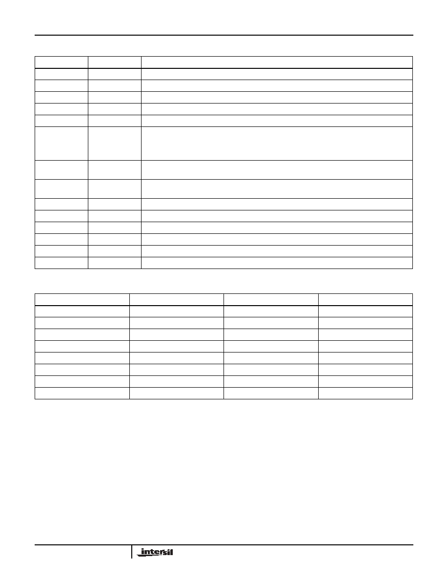
Pin Descriptions
PIN NUMBER
PIN NAME
FUNCTION
1, 2, 16
PROG A,B,C
Digital inputs to select ˜ N value for internal counter. See table below for values.
3
OSC/VCO OUT
Output of internal inverter/oscillator. Connect to external crystal or LC tank VCO circuit.
4
VDD (A)
Analog positive supply for oscillator, PLL circuits.
5
OSC/VCO IN
Input from external VCO.
6
VSS (A)
Analog ground for oscillator, PLL circuits.
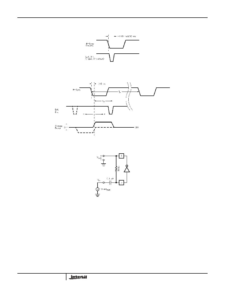
7
CHARGE PUMP
OUT
Connect to loop filter. If the H
SYNC
phase is leading or H
SYNC
frequency > CLK ˜ N, current is pumped
into the filter capacitor to increase VCO frequency. If H
SYNC
phase is lagging or frequency < CLK ˜ N,
current is pumped out of the filter capacitor to decrease VCO frequency. During coast mode or when
locked, charge pump goes to a high impedance state.
8
DIV SELECT
Divide select input. When high, the internal divider is enabled and EXT DIV becomes a test pin, outputting
CLK ˜ N. When low, the internal divider is disabled and EXT DIV is an input from an external ˜ N.
9
COAST
Tri-state logic input. Low (<1/3*V
CC
) = normal mode, Hi Z (or 1/3 to 2/3*V
CC
) = fast lock mode,
High (>2/3*V
CC
) = coast mode.
10
HSYNC IN
Horizontal sync pulse (CMOS level) input.
11
VDD (D)
Positive supply for digital, I/O circuits.
12
LOCK DET
Lock Detect output. Low level when PLL is locked. Pulses high when out of lock.
13
EXT DIV
External Divide input when DIV SEL is low, internal ˜N output when DIV SEL is high.
14
VSS (D)
Ground for digital, I/O circuits.
15
CLK OUT
Buffered output of the VCO.
TABLE 1. VCO DIVISORS
PROG A (PIN 16)
PROG B (PIN 1)
PROG C (PIN 2)
DIV VALUE (N)
0
0
0
851
0
0
1
864
0
1
0
944
0
1
1
1135
1
0
0
682
1
0
1
858
1
1
0
780
1
1
1
910
EL4584