1
Æ
FN7285.1
EL7242, EL7252
Dual Input, High Speed, Dual Channel
Power MOSFET Driver
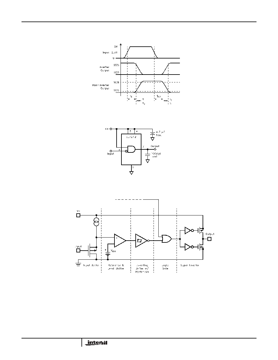
The EL7242/EL7252 dual input, 2-channel drivers achieve
the same excellent switching performance of the EL7212
family while providing added flexibility. The 2-input logic and
configuration is applicable to numerous power MOSFET
drive circuits. As with other Elantec drivers, the
EL7242/EL7252 are excellent for driving large capacitive
loads with minimal delay and switching times. "Shoot-thru"
protection and latching circuits can be implemented by
simply "cross-coupling" the 2-channels.
Features
∑ Logic AND/NAND input
∑ 3V and 5V Input compatible
∑ Clocking speeds up to 10MHz
∑ 20ns Switching/delay time
∑ 2A Peak drive
∑ Isolated drains
∑ Low output impedance
∑ Low quiescent current
∑ Wide operating voltage -- 4.5V16V
∑
Pb-Free available (RoHS compliant)
Applications
∑ Short circuit protected switching
∑ Under-voltage shut-down circuits
∑ Switch-mode power supplies
∑ Motor controls
∑ Power MOSFET switching
∑ Switching capacitive loads
∑ Shoot-thru protection
∑ Latching drivers
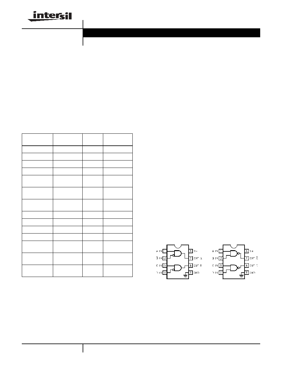
Pinouts
Ordering Information
PART NUMBER
PACKAGE
TAPE &
REEL
PKG. DWG. #
EL7242CN
8-Pin PDIP
-
MDP0031
EL7242CS
8-Pin SOIC
-
MDP0027
EL7242CS-T7
8-Pin SOIC
7"
MDP0027
EL7242CS-T13
8-Pin SOIC
13"
MDP0027
EL7242CSZ
(See Note)
8-Pin SOIC
(Pb-free)
-
MDP0027
EL7242CSZ-T7
(See Note)
8-Pin SOIC
(Pb-free)
7"
MDP0027
EL7242CSZ-T13
(See Note)
8-Pin SOIC
(Pb-free)
13"
MDP0027
EL7252CN
8-Pin PDIP
-
MDP0031
EL7252CS
8-Pin SOIC
-
MDP0027
EL7252CS-T7
8-Pin SOIC
7"
MDP0027
EL7252CS-T13
8-Pin SOIC
13"
MDP0027
EL7252CSZ
(See Note)
8-Pin SOIC
(Pb-free)
-
MDP0027
EL7252CSZ-T7
(See Note)
8-Pin SOIC
(Pb-free)
7"
MDP0027
EL7252CSZ-T13
(See Note)
8-Pin SOIC
(Pb-free)
13"
MDP0027
NOTE: Intersil Pb-free products employ special Pb-free material
sets; molding compounds/die attach materials and 100% matte tin
plate termination finish, which are RoHS compliant and compatible
with both SnPb and Pb-free soldering operations. Intersil Pb-free
products are MSL classified at Pb-free peak reflow temperatures that
meet or exceed the Pb-free requirements of IPC/JEDEC J STD-020.
EL7242
(8-PIN PDIP, SOIC)
TOP VIEW
EL7252
(8-PIN PDIP, SOIC)
TOP VIEW
Manufactured under U.S. Patent Nos. 5,334,883, #5,341,047
Data Sheet
April 6, 2005
CAUTION: These devices are sensitive to electrostatic discharge; follow proper IC Handling Procedures.
1-888-INTERSIL or 1-888-352-6832
|
Intersil (and design) is a registered trademark of Intersil Americas Inc.
Copyright Intersil Americas Inc. 2003, 2005. All Rights Reserved
All other trademarks mentioned are the property of their respective owners.
2
Absolute Maximum Ratings
(T
A
= 25∞C)
Supply (V+ to Gnd) . . . . . . . . . . . . . . . . . . . . . . . . . . . . . . . . . 16.5V
Input Pins . . . . . . . . . . . . . . . . . . . . . . . . . . -0.3V to +0.3V above V+
Combined Peak Output Current. . . . . . . . . . . . . . . . . . . . . . . . . . .4A
Storage Temperature Range . . . . . . . . . . . . . . . . . .-65∞C to +150∞C
Ambient Operating Temperature . . . . . . . . . . . . . . . . -40∞C to +85∞C
Operating Junction Temperature . . . . . . . . . . . . . . . . . . . . . . . 125∞C
Power Dissipation
SOIC . . . . . . . . . . . . . . . . . . . . . . . . . . . . . . . . . . . . . . 570mW
PDIP . . . . . . . . . . . . . . . . . . . . . . . . . . . . . . . . . . . . . 1050mW
CAUTION: Stresses above those listed in "Absolute Maximum Ratings" may cause permanent damage to the device. This is a stress only rating and operation of the
device at these or any other conditions above those indicated in the operational sections of this specification is not implied.
IMPORTANT NOTE: All parameters having Min/Max specifications are guaranteed. Typical values are for information purposes only. Unless otherwise noted, all tests
are at the specified temperature and are pulsed tests, therefore: T
J
= T
C
= T
A
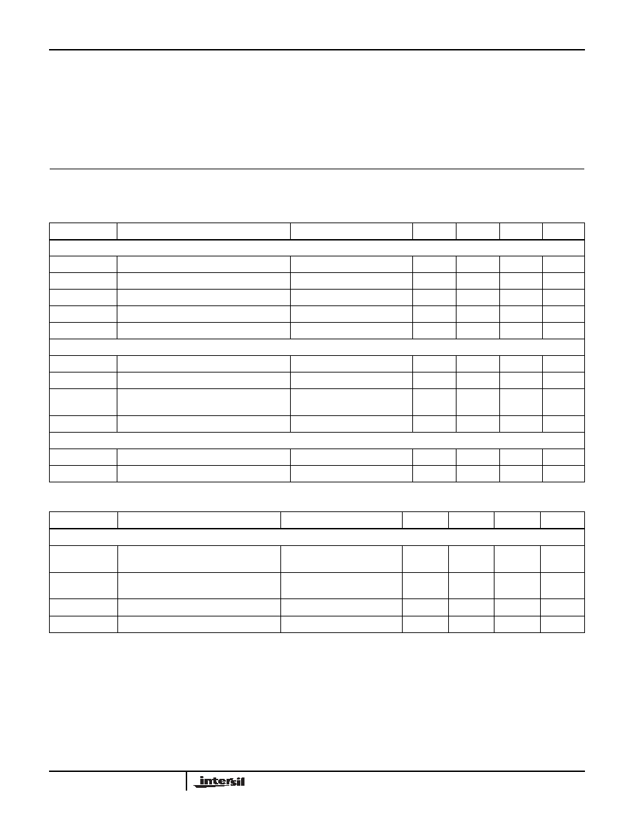
DC Electrical Specifications
T
A
= 25∞C, V = 15V unless otherwise specified
PARAMETER
DESCRIPTION
TEST CONDITIONS
MIN
TYP
MAX
UNITS
INPUT
V
IH
Logic "1' Input Voltage
2.4
V
I
IH
Logic "1' Input Current
@V+
0.1
10
µA
V
IL
Logic "0' Input Voltage
0.8
V
I
IL
Logic "0' Input Current
@0V
0.1
10
µA
V
HVS
Input Hysteresis
0.3
V
OUTPUT
R
OH
Pull-Up Resistance
I
OUT
= -100mA
3
6
R
OL
Pull-Down Resistance
I
OUT
= +100mA
4
6
I
PK
Peak Output Current
Source
Sink
2
2
A
I
DC
Continuous Output Current
Source/Sink
100
mA
POWER SUPPLY
I
S
Power Supply Current
Inputs High
1
2.5
mA
V
S
Operating Voltage
4.5
16
V
AC Electrical Specifications
T
A
= 25∞C, V = 15V unless otherwise specified
PARAMETER
DESCRIPTION
TEST CONDITIONS
MIN
TYP
MAX
UNITS
SWITCHING CHARACTERISTICS
t
R
Rise Time
C
L
= 500pF
C
L
= 1000pF
10
20
ns
t
F
Fall Time
C
L
= 500pF
C
L
= 1000pF
10
20
ns
t
D-ON
Turn-On Delay Time
20
25
ns
t
D-OFF
Turn-Off Delay Time
20
25
ns
EL7242, EL7252
4
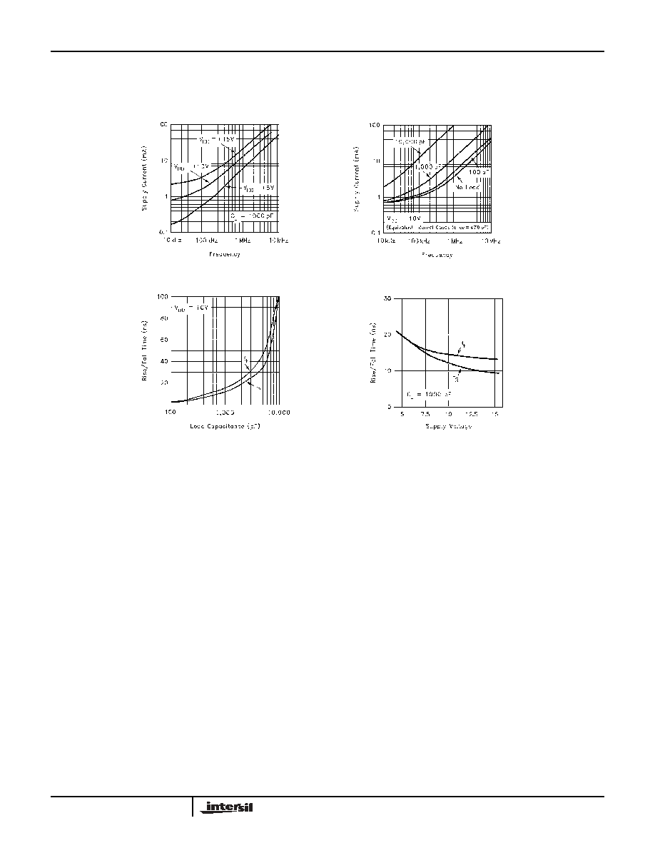
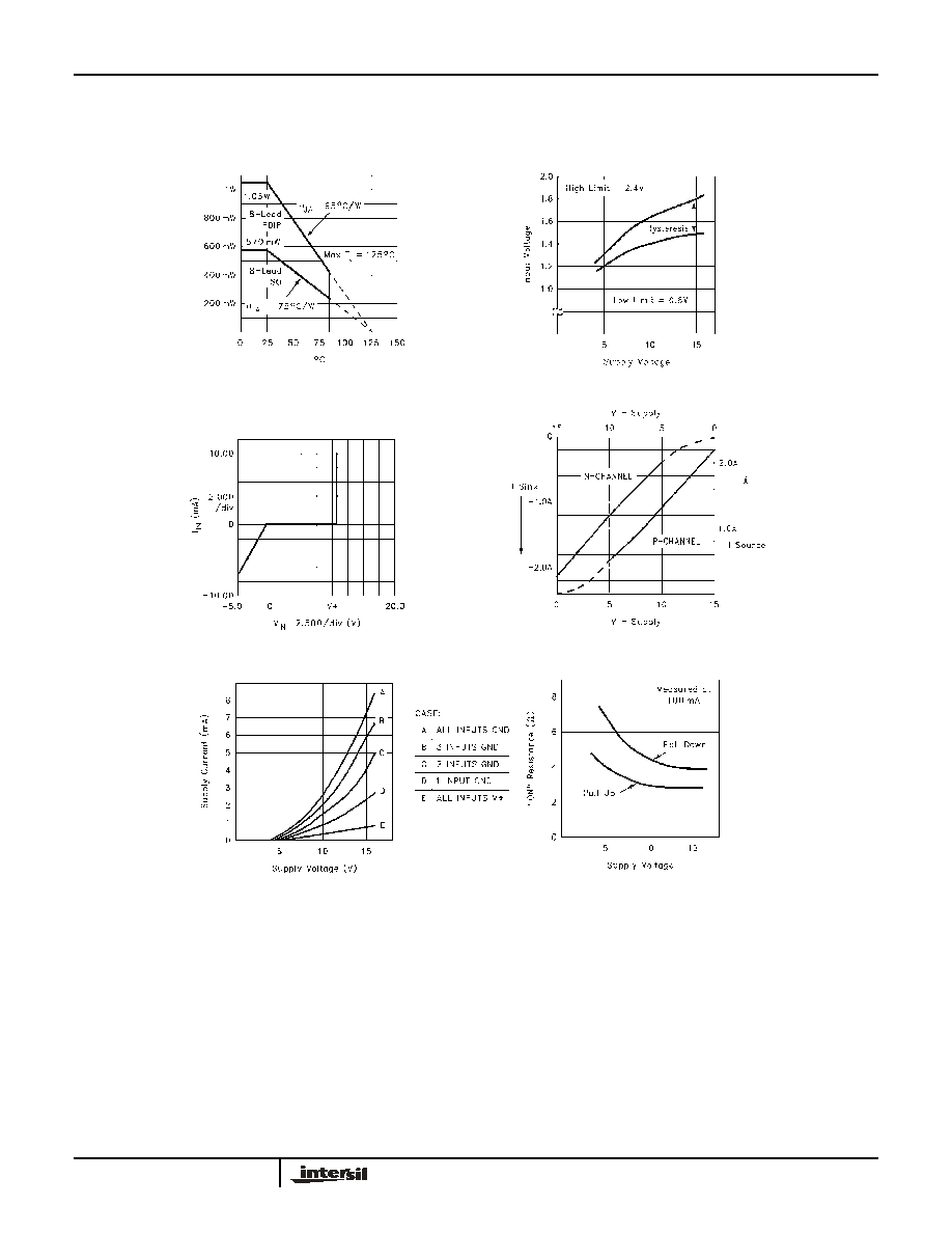
Typical Performance Curves
Max Power/Derating Curves
Switch Threshold vs Supply Voltage
Input Current vs Voltage
Quiescent Supply Current
"ON' Resistance vs Supply Voltage
Peak Drive vs Supply Voltage
EL7242, EL7252