
1
File Number
2899.3
CAUTION: These devices are sensitive to electrostatic discharge; follow proper IC Handling Procedures.
1-888-INTERSIL or 321-724-7143
|
Copyright
©
Intersil Corporation 1999
HA-2542
70MHz, High Slew Rate, High Output
Current Operational Amplifier
The HA-2542 is a wideband, high slew rate, monolithic
operational amplifier featuring an outstanding combination of
speed, bandwidth, and output drive capability.
Utilizing the advantages of the Intersil D.I. technology this
amplifier offers 350V/
µ
s slew rate, 70MHz gain bandwidth,
and
±
100mA output current. Application of this device is
further enhanced through stable operation down to closed
loop gains of 2.
For additional flexibility, offset null and frequency
compensation controls are included in the HA-2542 pinout.
The capabilities of the HA-2542 are ideally suited for high
speed coaxial cable driver circuits where low gain and high
output drive requirements are necessary. With 5.5MHz full
power bandwidth, this amplifier is most suitable for high
frequency signal conditioning circuits and pulse video
amplifiers. Other applications utilizing the HA-2542
advantages include wideband amplifiers and fast sample-
hold circuits.
For more information on the HA-2542, please refer to
Application Note AN552 (Using the HA-2542), or Application
Note AN556 (Thermal Safe-Operating-Areas for High
Current Op Amps).
Features
∑ Stable at Gains of 2 or Greater
∑ Gain Bandwidth . . . . . . . . . . . . . . . . . . . . . . . . . . . 70MHz
∑ High Slew Rate. . . . . . . . . . . . . . . . . . . . . . 300V/
µ
s (Min)
∑ High Output Current . . . . . . . . . . . . . . . . . . . 100mA (Min)
∑ Power Bandwidth . . . . . . . . . . . . . . . . . . . . . 5.5MHz (Typ)
∑ Output Voltage Swing . . . . . . . . . . . . . . . . . . .
±
10V (Min)
∑ Monolithic Bipolar Dielectric Isolation Construction
Applications
∑ Pulse and Video Amplifiers
∑ Wideband Amplifiers
∑ Coaxial Cable Drivers
∑ Fast Sample-Hold Circuits
∑ High Frequency Signal Conditioning Circuits
Pinout
HA-2542
(PDIP, CERDIP)
TOP VIEW
For a lower power version of this product, please see
the HA-2842 data sheet.
Ordering Information
PART NUMBER
TEMP.
RANGE (
o
C)
PACKAGE
PKG.
NO.
HA1-2542-5
0 to 75
14 Ld CERDIP
F14.3
HA3-2542-5
0 to 75
14 Ld PDIP
E14.3
NC
NC
BAL
-IN
+IN
V-
NC
NC
BAL
COMP
V+
OUT
NC
NC
1
2
3
4
5
6
7
14
13
12
11
10
9
8
+
-
Data Sheet
October 1999
2
Absolute Maximum Ratings
Thermal Information
Supply Voltage (Between V+ and V- Terminals) . . . . . . . . . . . . .35V
Differential Input Voltage . . . . . . . . . . . . . . . . . . . . . . . . . . . . . . . .6V
Output Current . . . . . . . . . . . . . . . . 50mA Continuous, 125mA
PEAK
Operating Conditions
Temperature Range
HA-2542-5 . . . . . . . . . . . . . . . . . . . . . . . . . . . . . . . . 0
o
C to 75
o
C
Thermal Resistance (Typical, Note 2)
JA
(
o
C/W)
JC
(
o
C/W)
CERDIP Package . . . . . . . . . . . . . . . . .
75
20
PDIP Package . . . . . . . . . . . . . . . . . . .
95
N/A
Maximum Junction Temperature (Note 1, Hermetic Packages) . 175
o
C
Maximum Junction Temperature (Plastic Package) . . . . . . . .150
o
C
Maximum Storage Temperature Range . . . . . . . . . . -65
o
C to 150
o
C
Maximum Lead Temperature (Soldering 10s) . . . . . . . . . . . . .300
o
C
CAUTION: Stresses above those listed in "Absolute Maximum Ratings" may cause permanent damage to the device. This is a stress only rating and operation of the
device at these or any other conditions above those indicated in the operational sections of this specification is not implied.
NOTES:
1. Maximum power dissipation with load conditions must be designed to maintain the maximum junction temperature below 175
o
C for ceramic
packages, and below 150
o
C for plastic packages. By using Application Note AN556 on Safe Operating Area equations, along with the thermal
resistances, proper load conditions can be determined. Heatsinking will be required in many applications. See the "Application Information"
section to determine if heat sinking is required for your application.
2.
JA
is measured with the component mounted on an evaluation PC board in free air.
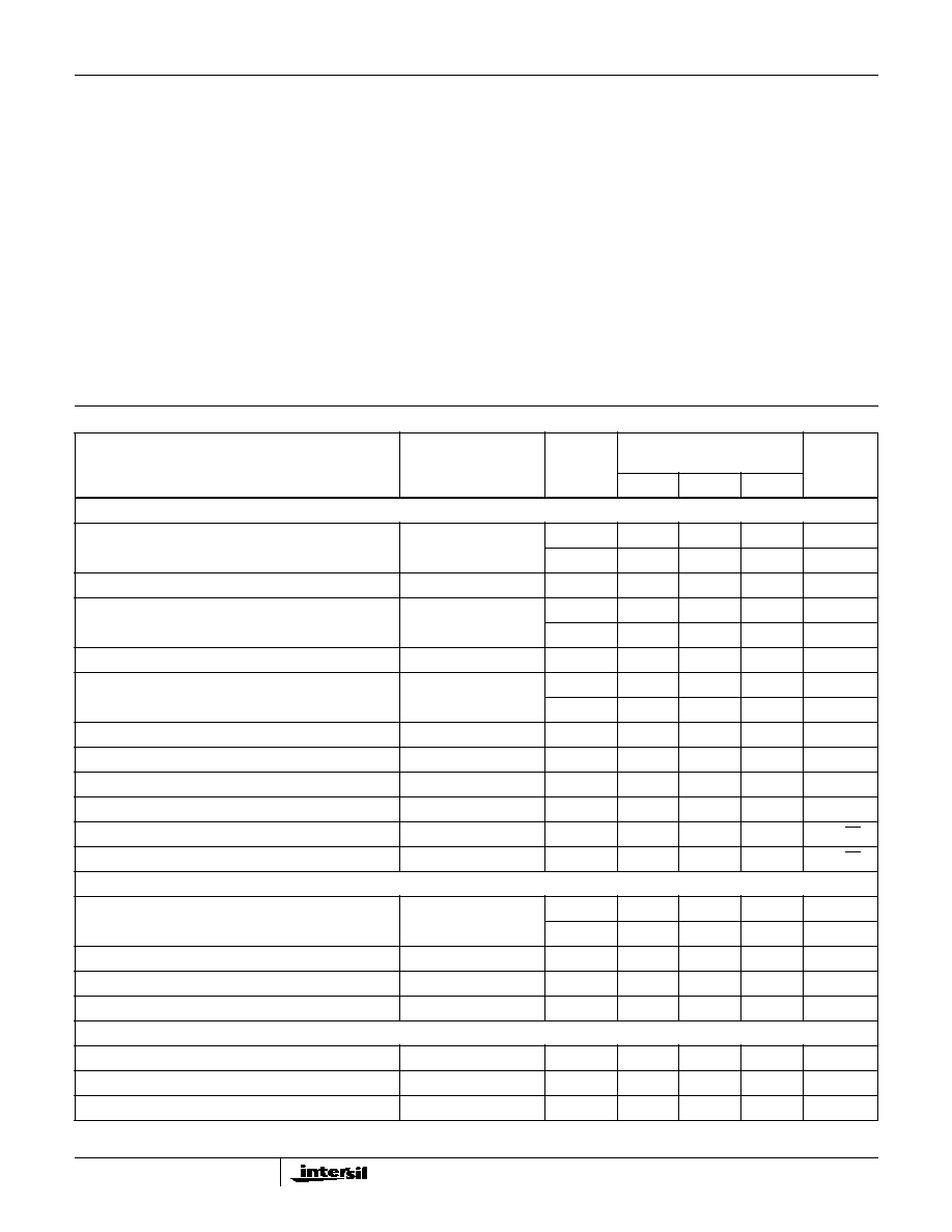
Electrical Specifications
V
SUPPLY
=
±
15V, R
L
= 1k
,
C
L
10pF, Unless Otherwise Specified
PARAMETER
TEST
CONDITIONS
TEMP.
(
o
C)
HA-2542-5
0
o
C TO 75
o
C
UNITS
MIN
TYP
MAX
INPUT CHARACTERISTICS
Offset Voltage
25
-
5
10
mV
Full
-
8
20
mV
Average Offset Voltage Drift
Full
-
14
-
µ
V/
o
C
Bias Current
25
-
15
35
µ
A
Full
-
26
50
µ
A
Average Bias Current Drift
Full
-
45
-
nA/
o
C
Offset Current
25
-
1
7
µ
A
Full
-
-
9
µ
A
Input Resistance
25
-
100
-
k
Input Capacitance
25
-
1
-
pF
Common Mode Range
Full
±
10
-
-
V
Input Noise Voltage
0.1Hz to 100Hz
25
-
2.2
-
µ
V
P-P
Input Noise Density
f = 1kHz, R
G
= 0
25
-
10
-
nV/
Hz
Input Noise Current Density
f = 1kHz, R
G
= 0
25
-
3
-
pA/
Hz
TRANSFER CHARACTERISTICS
Large Signal Voltage Gain
V
O
=
±
10V
25
10
30
-
kV/V
Full
5
20
-
kV/V
Common Mode Rejection Ratio
V
CM
=
±
10V
Full
70
100
-
dB
Minimum Stable Gain
25
2
-
-
V/V
Gain Bandwidth Product
A
V
= 100
25
-
70
-
MHz
OUTPUT CHARACTERISTICS
Output Voltage Swing
Full
±
10
±
11
-
V
Output Current (Note 3)
25
100
-
-
mA
Output Resistance
25
-
5
-
HA-2542
3
Full Power Bandwidth (Note 4)
V
PEAK
= 10V
25
4.7
5.5
-
MHz
Differential Gain (Note 5)
25
-
0.1
-
%
Differential Phase (Note 5)
25
-
0.2
-
Degree
Harmonic Distortion (Note 7)
25
-
<0.04
-
%
TRANSIENT RESPONSE (Note 6)
Rise Time
25
-
4
-
ns
Overshoot
25
-
25
-
%
Slew Rate
25
300
350
-
V/
µ
s
Settling Time
10V Step to 0.1%
25
-
100
-
ns
10V Step to 0.01%
25
-
200
-
ns
POWER SUPPLY CHARACTERISTICS
Supply Current
25
-
30
-
mA
Full
-
31
40
mA
Power Supply Rejection Ratio
V
S
=
±
5V to
±
15V
Full
70
79
-
dB
NOTES:
3. R
L
= 50
, V
O
=
±
5V, Output duty cycle must be reduced for I
OUT
> 50mA (e.g.
50% duty cycle for 100mA).
4. Full Power Bandwidth guaranteed based on slew rate measurement using:
.
5. Differential gain and phase are measured at 5MHz with a 1V differential input voltage.
6. Refer to Test Circuits section of this data sheet.
7. V
IN
= 1V
RMS
; f = 10kHz; A
V
= 10.
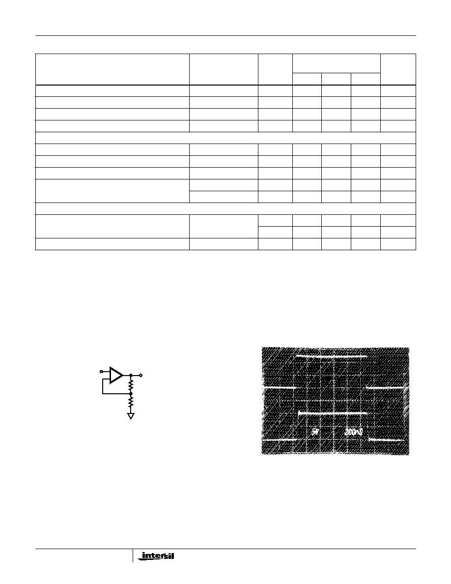
Test Circuits and Waveforms
TEST CIRCUIT
LARGE SIGNAL RESPONSE
Electrical Specifications
V
SUPPLY
=
±
15V, R
L
= 1k
,
C
L
10pF, Unless Otherwise Specified (Continued)
PARAMETER
TEST
CONDITIONS
TEMP.
(
o
C)
HA-2542-5
0
o
C TO 75
o
C
UNITS
MIN
TYP
MAX
FPBW
Slew Rate
2
V
PEAK
-----------------------------
=
IN
OUT
+
-
500
500
NOTES:
8. V
S
=
±
15V.
9. A
V
= +2.
10. C
L
10pF.
V
IN
V
OUT
Vertical Scale: V
IN
= 2.0V/Div., V
OUT
= 5.0V/Div.
Horizontal Scale: 200ns/Div.
HA-2542

4
Schematic Diagram
SMALL SIGNAL RESPONSE
PROPAGATION DELAY
SETTLING TIME TEST CIRCUIT (SEE NOTES 11 - 15.)
NOTES:
11. A
V
= -2.
12. Feedback and summing resistors must be matched (0.1%).
13. HP5082-2810 clipping diodes recommended.
14. Tektronix P6201 FET probe used at settling point.
15. For 0.01% settling time, heat sinking is suggested to reduce
thermal effects and an analog ground plane with supply
decoupling is suggested to minimize ground loop errors.
Test Circuits and Waveforms
(Continued)
V
IN
V
OUT
Vertical Scale: 100mV/Div.
Horizontal Scale: 50ns/Div.
Vertical Scale: 100mV/Div.
Horizontal Scale: 10ns/Div.
V
S
=
±
15V, R
L
= 1k
. Propagation delay variance
is negligible over full temperature range.
SETTLING
POINT
V
OUT
5k
V+
500
V-
+
-
1k
V
IN
2.5k
R
11
R
7
R
8
R
9
R
10
75
R
25
5k
R
12
75
R
15
Q
P15
Q
P13
Q
P14
Q
P34
Q
P16
Q
P35
Q
P33
Q
P32
Q
N
Q
P36
Q
N23
Q
P7
Q
P5
C
1
COMP
Q
N2
-IN
Q
N1
+IN
R
6
Q
N18
R
14
Q
N12
Q
P11
Q
P31
Q
N42
R
18
Q
N44
D
Z45
BAL
BAL
R
26
5k
HA-2542

5
Application Information
(Refer to Application Note AN552 for Further Information)
The Intersil HA-2542 is a state of the art monolithic device
which also approaches the "ALL-IN-ONE" amplifier concept.
This device features an outstanding set of AC parameters
augmented by excellent output drive capability providing for
suitable application in both high speed and high output drive
circuits.
Primarily intended to be used in balanced 50
and 75
coaxial cable systems as a driver, the HA-2542 could also be
used as a power booster in audio systems as well as a
power amp in power supply circuits. This device would also
be suitable as a small DC motor driver.
The applications shown in Figures 2 through Figure 4
demonstrate the HA-2542 at gains of +100 and +2 and as a
video cable driver for small signals.
Power Dissipation Considerations
At high output currents, especially with the PDIP package,
care must be taken to ensure that the Maximum Junction
Temperature (T
J
, see "Absolute Maximum Ratings" table) is
not exceeded. As an example consider the HA-2542 in the
PDIP package, with a required output current of 20mA at
V
OUT
= 5V. The power dissipation is the quiescent power
(1.2W = 30V x 40mA) plus the power dissipated in the
output stage (P
OUT
= 200mW = 20mA x (15V - 5V)), or a
total of 1.4W. The thermal resistance (
JA
) of the PDIP
package is 100
o
C/W, which increases the junction
temperature by 140
o
C over the ambient temperature (T
A
).
Remaining below T
JMAX
requires that T
A
be restricted to
10
o
C (150
o
C - 140
o
C). Heatsinking would be required for
operation at ambient temperatures greater than 10
o
C.
Note that the problem isn't as severe with the CERDIP
package due to it's lower thermal resistance, and higher
T
JMAX
. Nevertheless, it is recommended that Figure 1 be
used to ensure that heat sinking is not required.
Allowable output power can be increased by decreasing the
quiescent dissipation via lower supply voltages.
For more information please refer to Application Note
AN556, "Thermal Safe Operating Areas for High Current Op
Amps".
Prototyping Guidelines
For best overall performance in any application, it is
recommended that high frequency layout techniques be
used. This should include: 1) mounting the device through a
ground plane: 2) connecting unused pins (NC) to the ground:
3) mounting feedback components on Teflon standoffs and
or locating these components as close to the device as
possible: 4) placing power supply decoupling capacitors
from device supply pins to ground.
OUTPUT CURRENT (100% DUTY CYCLE, mA)
MAXIMUM T
A
WITHOUT HEA
TSINK (
o
C)
0
5
10
15
20
25
30
35
40
45
50
0
20
40
60
80
100
120
CERDIP
PDIP
V
OUT
=
±
5V
V
S
=
±
15V
FIGURE 1. MAXIMUM OPERATING TEMPERATURE vs
OUTPUT CURRENT
HA-2542
6
Frequency Compensation
The HA-2542 may be externally compensated with a single
capacitor to ground. This provides the user the additional
flexibility in tailoring the frequency response of the amplifier.
A guideline to the response is demonstrated on the typical
performance curve showing the normalized AC parameters
versus compensation capacitance. It is suggested that the
user check and tailor the accurate compensation value for
each application. As shown additional phase margin is
achieved at the loss of slew rate and bandwidth.
For example, for a voltage gain of +2 (or -1) and a load of
500pF/2k
, 20pF is needed for compensation to give a small
signal bandwidth of 30MHz with 40
o
of phase margin. If a full
power output voltage of
±
10V is needed, this same
configuration will provide a bandwidth of 5MHz and a slew
rate of 200V/
µ
s.
If maximum bandwidth is desired and no compensation is
needed, care must be given to minimize parasitic
capacitance at the compensation pin. In some cases where
minimum gain applications are desired, bending up or totally
removing this pin may be the solution. In this case, care
must also be given to minimize load capacitance.
For wideband positive unity gain applications, the HA-2542
can also be over-compensated with capacitance greater
than 30pF to achieve bandwidths of around 25MHz. This
over-compensation will also improve capacitive load
handling or lower the noise bandwidth. This versatility along
with the
±
100mA output current makes the HA-2542 an
excellent high speed driver for many power applications.
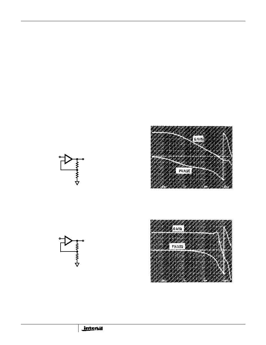
Typical Applications
FIGURE 2. NONINVERTING CIRCUIT (A
VCL
= 100)
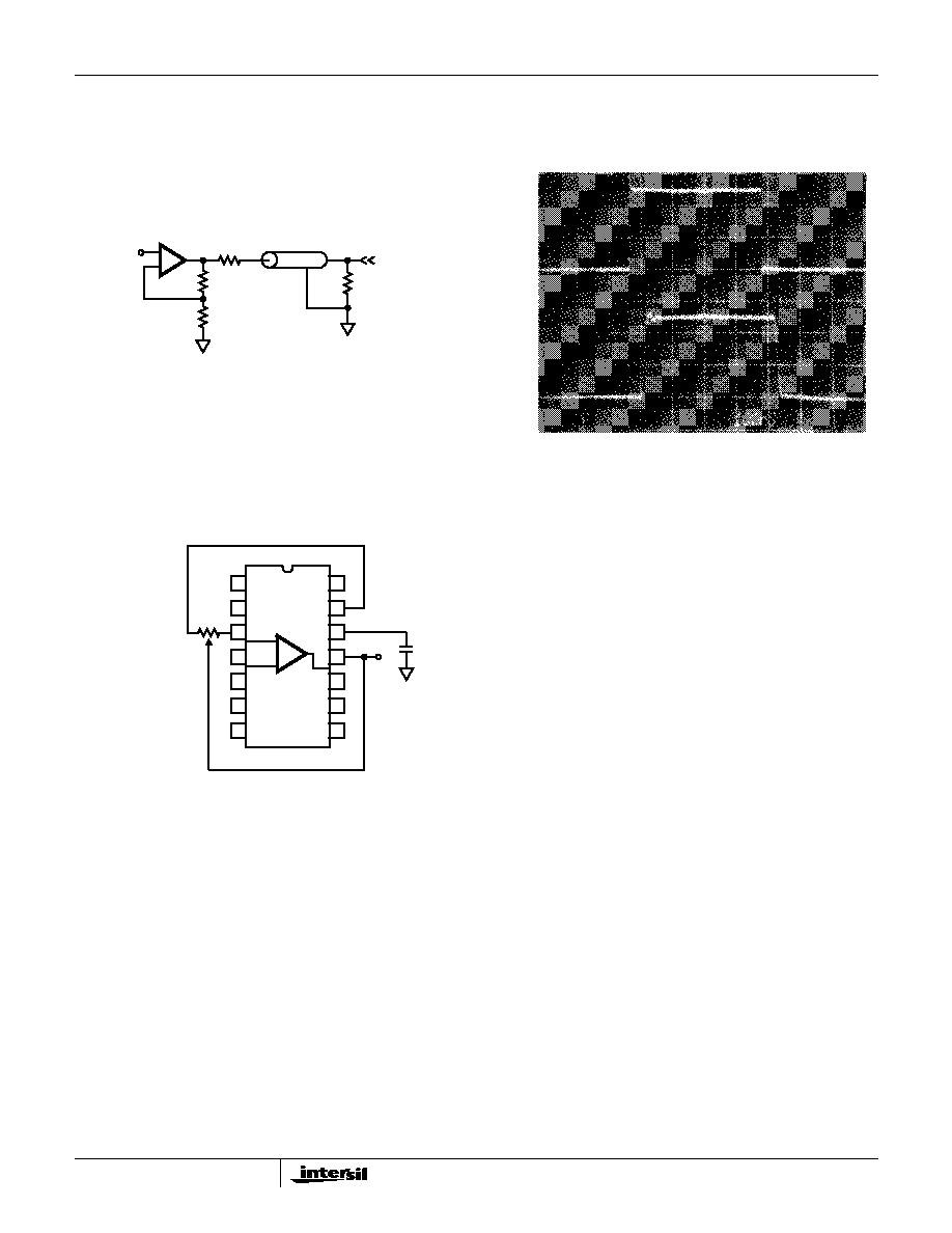
FIGURE 3. NONINVERTING CIRCUIT (A
VCL
= 2)
IN
OUT
+
-
990
10
GAIN (dB)
40
30
20
10
0
0
-45
-90
-135
-180
PHASE (DEGREES)
Frequency (0dB) = 44.9MHz,
Phase Margin (0dB) = 40
o
FREQUENCY RESPONSE
IN
OUT
+
-
50
50
GAIN (dB)
8
6
4
2
0
0
-45
-90
-135
-180
PHASE (DEGREES)
Frequency (dB) = 56MHz, Phase Margin (3dB) = 40
o
FREQUENCY RESPONSE
HA-2542
7
PULSE RESPONSE
FIGURE 4. VIDEO CABLE DRIVER (A
VCL
= 2)
FIGURE 5. SUGGESTED OFFSET VOLTAGE ADJUSTMENT AND FREQUENCY COMPENSATION
Typical Applications
(Continued)
IN
OUT
+
-
1k
75
1k
75
IN
OUT
1V/Div.; 100ns/Div.
NOTES:
16. Suggested compensation scheme 5pF - 20pF.
17. Tested Offset Adjustment Range is |V
OS
+1mV|
minimum referred to output.
18. Typical range is
±
20mV with R
T
= 5k
.
1
2
3
4
5
6
7
14
13
12
11
10
9
8
+
-
R
T
C
COMP
V+
HA-2542

8
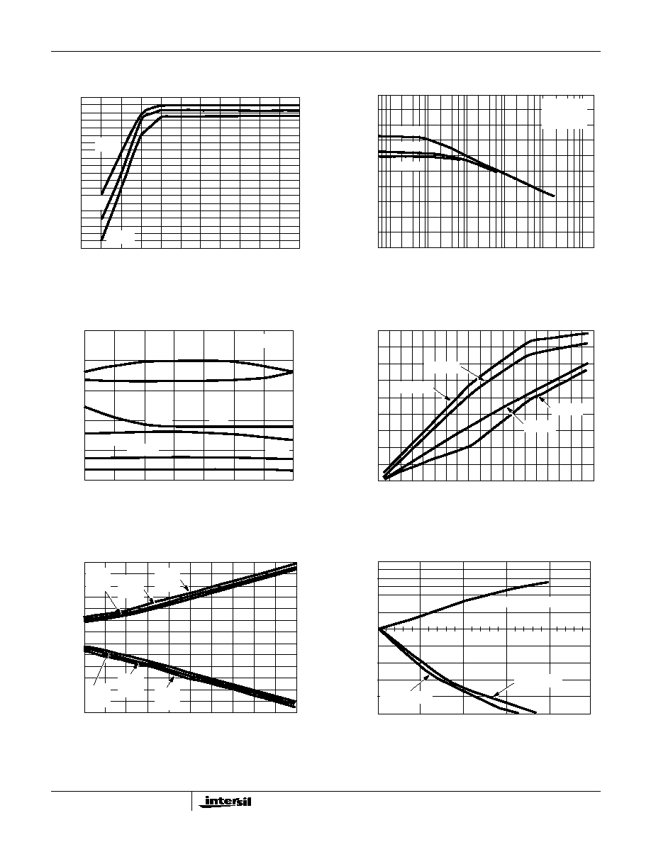
Typical Performance Curves
FIGURE 6. INPUT NOISE VOLTAGE AND INPUT NOISE
CURRENT vs FREQUENCY
FIGURE 7. OFFSET VOLTAGE vs TEMPERATURE
FIGURE 8. INPUT RESISTANCE vs FREQUENCY
FIGURE 9. BIAS CURRENT vs TEMPERATURE
FIGURE 10. BIAS CURRENT vs SUPPLY VOLTAGE
FIGURE 11. PSRR AND CMRR vs TEMPERATURE
INPUT NOISE V
O
L
T
A
GE (nV/
Hz)
FREQUENCY (Hz)
INPUT NOISE VOLTAGE
INPUT NOISE CURRENT
1000
100
10
1
10
100
1K
10K
100K
1000
100
10
INPUT NOISE CURRENT (pA/
Hz)
1
1
OFFSET V
O
L
T
A
GE (mV)
TEMPERATURE (
o
C)
10
8
6
4
2
0
-2
-4
-6
-8
-10
-60
-40
-20
0
20
40
60
80
100
120
V
S
=
±
12V
SIX REPRESENTATIVE UNITS
INPUT RESIST
ANCE (
)
FREQUENCY (Hz)
100K
10K
1000
100
10
100K
1M
10M
100M
T
A
= 25
o
C
V
S
=
±
15V
+
-
V-
900
100
V+
BIAS CURRENT (
µ
A)
TEMPERATURE (
o
C)
-60
-40
-20
0
20
40
60
80
100
120
29
27
25
23
21
19
17
15
13
11
9
7
V
S
=
±
12V
SIX REPRESENTATIVE UNITS
BIAS CURRENT (
µ
A)
SUPPLY VOLTAGE (
±
V)
18
17
16
15
14
13
12
11
10
9
8
7
5
7
9
11
13
15
T
A
= 25
o
C
SIX REPRESENTATIVE UNITS
TEMPERATURE (
o
C)
(dB)
CMRR
PSRR
120
110
100
90
80
70
-60
-40
-20
0
20
40
60
80
100
120
V
S
=
±
15V
HA-2542
9
FIGURE 12. SUPPLY CURRENT vs SUPPLY VOLTAGE, AT
VARIOUS TEMPERATURES
FIGURE 13. PSRR AND CMRR vs FREQUENCY
FIGURE 14. SLEW RATE vs TEMPERATURE AT VARIOUS
SUPPLY VOLTAGES
FIGURE 15. OPEN LOOP GAIN vs TEMPERATURE, AT
VARIOUS SUPPLY VOLTAGES
FIGURE 16. OUTPUT VOLTAGE SWING vs SUPPLY VOLTAGE,
AT VARIOUS TEMPERATURES
FIGURE 17. NORMALIZED AC PARAMETERS vs
COMPENSATION CAPACITANCE
Typical Performance Curves
(Continued)
25
o
C
125
o
C
-55
o
C
SUPPL
Y CURRENT (mA)
SUPPLY VOLTAGE (
±
V)
32
30
28
26
24
22
20
18
16
14
12
4
6
8
10
12
14
(dB)
FREQUENCY (Hz)
120
100
80
60
40
20
0
100
1K
10K
100K
1M
10M
-PSRR
+PSRR
CMRR
V
S
=
±
15V
T
A
= 25
o
C
R
L
= 2k
TEMPERATURE (
o
C)
SLEW RA
TE (V/
µ
s)
500
400
300
200
100
0
-50
-25
0
25
50
75
100
125
R
L
= 100
±
15V
±
5V
±
10V
A
V
= 10
A
V
= 2
A
V
= 2
A
V
= 2
A
V
= 10
A
V
= 10
±
5V
±
10V
±
15V
A
VO
L
(kV/V)
TEMPERATURE (
o
C)
55
50
45
40
35
30
25
20
15
10
-60
-40
-20
0
20
40
60
80
100
120
V
S
=
±
12
V
S
=
±
7
V
S
=
±
8
V
S
=
±
15
OUTPUT V
O
L
T
A
GE SWING (V)
SUPPLY VOLTAGE (
±
V)
12.0
10.0
8.0
6.0
4.0
2.0
0.0
-2.0
-4.0
-6.0
-8.0
-10.0
-12.0
-14.0
5
7
9
11
13
15
-55
o
C
+V
OUT
25
o
C
+V
OUT
125
o
C
+V
OUT
-55
o
C
-V
OUT
25
o
C
-V
OUT
125
o
C
-V
OUT
NORMALIZED T
O
V
ALUE A
T
0pF
COMPENSATION CAPACITANCE (pF)
1.4
1.3
1.2
1.1
1.0
0.9
0.8
0.7
0.6
0.5
5
10
15
20
25
SLEW RATE
PHASE MARGIN
BANDWIDTH
0
HA-2542

10
FIGURE 18. OUTPUT VOLTAGE SWING vs FREQUENCY
FIGURE 19. OUTPUT VOLTAGE SWING vs FREQUENCY
FIGURE 20. FREQUENCY RESPONSE CURVES
FIGURE 21. HA-2542 CLOSED LOOP GAIN vs TEMPERATURE
Typical Performance Curves
(Continued)
FREQUENCY (Hz)
12
10
8
6
4
2
0
0.1
1
10
100
UNDISTORTED
A
V
= 10
V
S
=
±
15V
T
A
= 25
o
C
HA-2542
SWING
R
L
= 1k
MAXIMUM SWING
OUTPUT V
O
L
T
A
GE (V)
R
L
= 100
MAXIMUM SWING
UNDISTORTED SWING
FREQUENCY (Hz)
OUTPUT V
O
L
T
A
GE (V)
12
10
8
6
4
2
0
0.1
1
10
100
R
L
= 100
MAXIMUM SWING
UNDISTORTED SWING
R
L
= 1k
MAXIMUM SWING
UNDISTORTED SWING
A
V
= 10
V
S
=
±
10V
T
A
= 25
o
C
HA-2542
A
V
= 1000
FREQUENCY (MHz)
GAIN (dB)
70
60
50
40
30
20
10
0
0.1
1
10
100
A
V
= 100
A
V
= 10
A
V
= 2
T
A
= 25
o
C
R
L
= 1k
V
S
=
±
15V
HA-2542
GAIN (dB)
12
9
6
3
100K
1M
10M
100M
+
-
V-
500
500
V+
0
V
IN
-180
-135
-90
-45
0
PHASE (DEGREES)
GAIN = +2
V
S
=
±
8V
R
L
= 1k
C
L
10pF
V
IN
90mV
GAIN
PHASE
25
o
C
125
o
C
-55
o
C
FREQUENCY (Hz)
25
o
C
125
o
C
-55
o
C
HA-2542
11
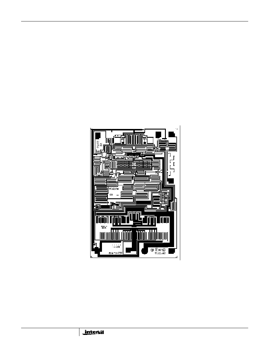
Die Characteristics
DIE DIMENSIONS:
106 mils x 73 mils x 19 mils
2700
µ
m x 1850
µ
m x 483
µ
m
METALLIZATION:
Type: Al, 1% Cu
Thickness: 16k
≈
±
2k
≈
PASSIVATION
Type: Nitride (Si
3
N
4)
over Silox (SiO
2
, 5% Phos.)
Silox Thickness: 12k
≈
±
2k
≈
Nitride Thickness: 3.5k
≈
±
1.5k
≈
SUBSTRATE POTENTIAL (POWERED UP):
V-
TRANSISTOR COUNT:
43
PROCESS:
Bipolar Dielectric Isolation
Metallization Mask Layout
HA-2542
COMP
V+
OUTPUT
V-
+IN
-IN
BAL
BAL
HA-2542
12
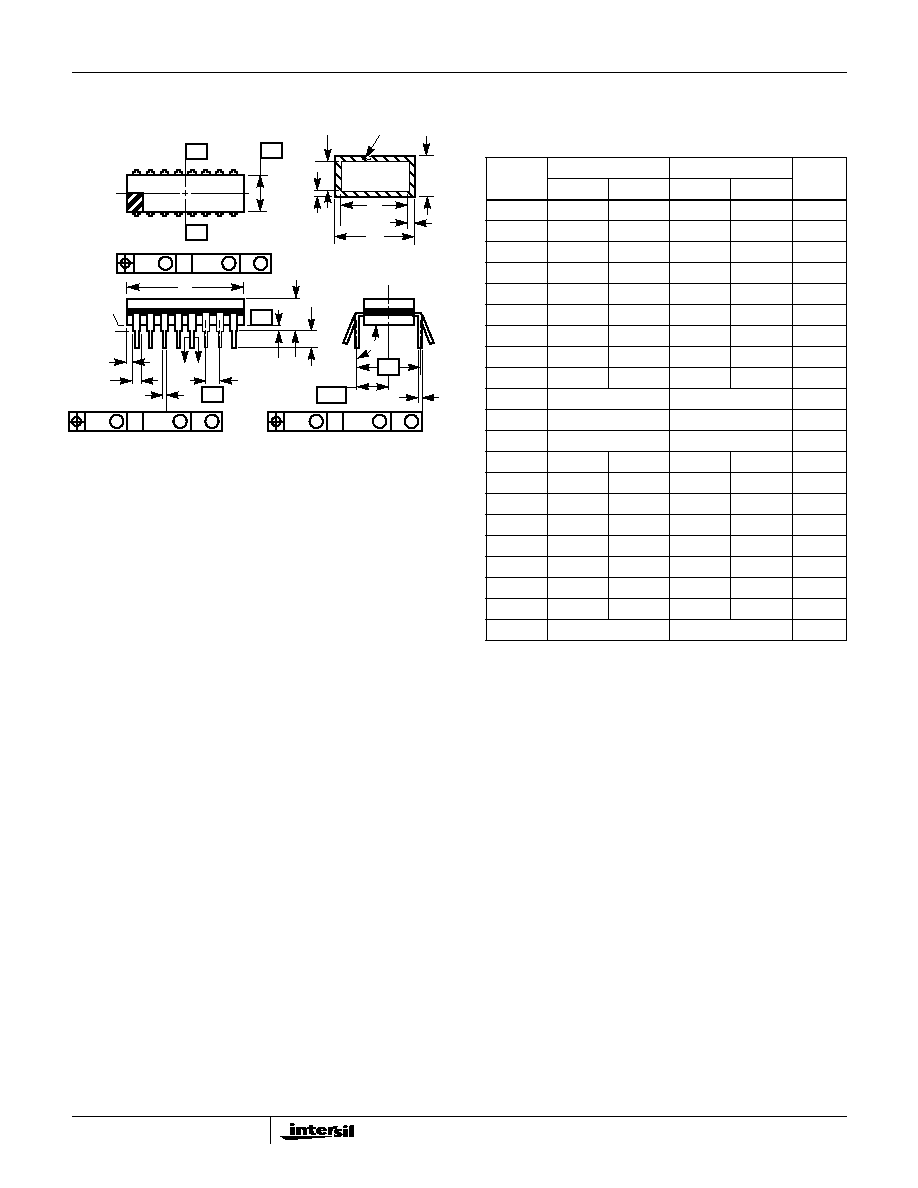
HA-2542
Ceramic Dual-In-Line Frit Seal Packages (CERDIP)
NOTES:
1. Index area: A notch or a pin one identification mark shall be locat-
ed adjacent to pin one and shall be located within the shaded
area shown. The manufacturer's identification shall not be used
as a pin one identification mark.
2. The maximum limits of lead dimensions b and c or M shall be
measured at the centroid of the finished lead surfaces, when
solder dip or tin plate lead finish is applied.
3. Dimensions b1 and c1 apply to lead base metal only. Dimension
M applies to lead plating and finish thickness.
4. Corner leads (1, N, N/2, and N/2+1) may be configured with a
partial lead paddle. For this configuration dimension b3 replaces
dimension b2.
5. This dimension allows for off-center lid, meniscus, and glass
overrun.
6. Dimension Q shall be measured from the seating plane to the
base plane.
7. Measure dimension S1 at all four corners.
8. N is the maximum number of terminal positions.
9. Dimensioning and tolerancing per ANSI Y14.5M - 1982.
10. Controlling dimension: INCH.
bbb
C A - B
S
c
Q
L
A
SEATING
BASE
D
PLANE
PLANE
-D-
-A-
-C-
-B-
D
E
S1
b2
b
A
e
M
c1
b1
(c)
(b)
SECTION A-A
BASE
LEAD FINISH
METAL
e
A/2
A
M
S
S
ccc
C A - B
M
D
S
S
aaa
C A - B
M
D
S
S
e
A
F14.3
MIL-STD-1835 GDIP1-T14 (D-1, CONFIGURATION A)
14 LEAD CERAMIC DUAL-IN-LINE FRIT SEAL PACKAGE
SYMBOL
INCHES
MILLIMETERS
NOTES
MIN
MAX
MIN
MAX
A
-
0.200
-
5.08
-
b
0.014
0.026
0.36
0.66
2
b1
0.014
0.023
0.36
0.58
3
b2
0.045
0.065
1.14
1.65
-
b3
0.023
0.045
0.58
1.14
4
c
0.008
0.018
0.20
0.46
2
c1
0.008
0.015
0.20
0.38
3
D
-
0.785
-
19.94
5
E
0.220
0.310
5.59
7.87
5
e
0.100 BSC
2.54 BSC
-
eA
0.300 BSC
7.62 BSC
-
eA/2
0.150 BSC
3.81 BSC
-
L
0.125
0.200
3.18
5.08
-
Q
0.015
0.060
0.38
1.52
6
S1
0.005
-
0.13
-
7
90
o
105
o
90
o
105
o
-
aaa
-
0.015
-
0.38
-
bbb
-
0.030
-
0.76
-
ccc
-
0.010
-
0.25
-
M
-
0.0015
-
0.038
2, 3
N
14
14
8
Rev. 0 4/94
13
All Intersil semiconductor products are manufactured, assembled and tested under ISO9000 quality systems certification.
Intersil semiconductor products are sold by description only. Intersil Corporation reserves the right to make changes in circuit design and/or specifications at any time with-
out notice. Accordingly, the reader is cautioned to verify that data sheets are current before placing orders. Information furnished by Intersil is believed to be accurate and
reliable. However, no responsibility is assumed by Intersil or its subsidiaries for its use; nor for any infringements of patents or other rights of third parties which may result
from its use. No license is granted by implication or otherwise under any patent or patent rights of Intersil or its subsidiaries.
For information regarding Intersil Corporation and its products, see web site www.intersil.com
Sales Office Headquarters
NORTH AMERICA
Intersil Corporation
P. O. Box 883, Mail Stop 53-204
Melbourne, FL 32902
TEL: (321) 724-7000
FAX: (321) 724-7240
EUROPE
Intersil SA
Mercure Center
100, Rue de la Fusee
1130 Brussels, Belgium
TEL: (32) 2.724.2111
FAX: (32) 2.724.22.05
ASIA
Intersil (Taiwan) Ltd.
7F-6, No. 101 Fu Hsing North Road
Taipei, Taiwan
Republic of China
TEL: (886) 2 2716 9310
FAX: (886) 2 2715 3029
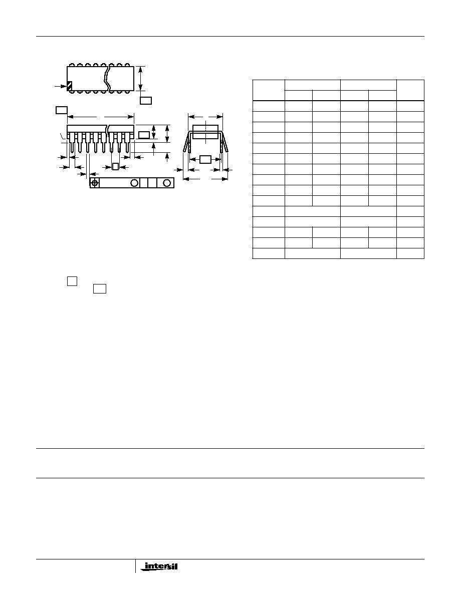
HA-2542
Dual-In-Line Plastic Packages (PDIP)
NOTES:
1. Controlling Dimensions: INCH. In case of conflict between English
and Metric dimensions, the inch dimensions control.
2. Dimensioning and tolerancing per ANSI Y14.5M-1982.
3. Symbols are defined in the "MO Series Symbol List" in Section 2.2 of
Publication No. 95.
4. Dimensions A, A1 and L are measured with the package seated in
JEDEC seating plane gauge GS-3.
5. D, D1, and E1 dimensions do not include mold flash or protrusions.
Mold flash or protrusions shall not exceed 0.010 inch (0.25mm).
6. E and
are measured with the leads constrained to be perpen-
dicular to datum
.
7. e
B
and e
C
are measured at the lead tips with the leads uncon-
strained. e
C
must be zero or greater.
8. B1 maximum dimensions do not include dambar protrusions. Dambar
protrusions shall not exceed 0.010 inch (0.25mm).
9. N is the maximum number of terminal positions.
10. Corner leads (1, N, N/2 and N/2 + 1) for E8.3, E16.3, E18.3, E28.3,
E42.6 will have a B1 dimension of 0.030 - 0.045 inch (0.76 -
1.14mm).
e
A
-C-
C
L
E
e
A
C
e
B
e
C
-B-
E1
INDEX
1 2 3
N/2
N
AREA
SEATING
BASE
PLANE
PLANE
-C-
D1
B1
B
e
D
D1
A
A2
L
A1
-A-
0.010 (0.25)
C
A
M
B S
E14.3
(JEDEC MS-001-AA ISSUE D)
14 LEAD DUAL-IN-LINE PLASTIC PACKAGE
SYMBOL
INCHES
MILLIMETERS
NOTES
MIN
MAX
MIN
MAX
A
-
0.210
-
5.33
4
A1
0.015
-
0.39
-
4
A2
0.115
0.195
2.93
4.95
-
B
0.014
0.022
0.356
0.558
-
B1
0.045
0.070
1.15
1.77
8
C
0.008
0.014
0.204
0.355
-
D
0.735
0.775
18.66
19.68
5
D1
0.005
-
0.13
-
5
E
0.300
0.325
7.62
8.25
6
E1
0.240
0.280
6.10
7.11
5
e
0.100 BSC
2.54 BSC
-
e
A
0.300 BSC
7.62 BSC
6
e
B
-
0.430
-
10.92
7
L
0.115
0.150
2.93
3.81
4
N
14
14
9
Rev. 0 12/93