1
File Number
4777
CAUTION: These devices are sensitive to electrostatic discharge; follow proper IC Handling Procedures.
1-888-INTERSIL or 407-727-9207
|
Copyright
©
Intersil Corporation 1999
CoolaudioTM is a trademark of Intersil Corporation.
P R E L I M I N A R Y
HCA600ACREF
600W/1000W Full Bandwidth Class D
Amplifier
The HCA600ACREF reference
design delivers 600W RMS
power into a 8
load and
1000W into a 4
load.
The design is part of the Intersil's CoolaudioTM program that
supports customers to achieve a minimum time-to-market for
audio end products. As part of this program, this design is
offered after execution of a licensing agreement. At that time,
Intersil provides to the licensee a documentation package
containing: 1) a circuit description, 2) schematics, 3) test
and manufacturing information, 4) A bill of materials with all
vendors and vendor part numbers, 5) Intersil's engineering
support contacts, 6) one evaluation unit.
For more information, visit our web page at
http://www.intersil.com. For technical assistance, call Central
Applications at 1-800-442-7747, or email us at
centapp@intersil.com.
Licensing Information
Contacts for licensing details, reference design evaluation,
and general questions are as follows:
Continental Far East, Email cfelic@ca.mbn.or.jp
Intersil Cool Audio, Email coolaud@intersil.com
Features
∑ 600W RMS Power into 8
∑ 1000W RMS Power into 4
∑ THD <0.02% at 1kHz and 450W into 8
∑ SNR >110dB Relative to Full Power
∑ Output Noise . . . . . . . . . . . . . . . . . . . . . . . . . . . . <200
µ
V
∑ Constant Group Delay
∑ DC to 80kHz Small Signal Bandwidth
∑ Power Bandwidth . . . . . . . . . . . . . . . . . . . . . . . . . . .28kHz
∑ Slew Rate . . . . . . . . . . . . . . . . . . . . . . . . . . . . . . . . 18V/
µ
s
∑ Efficiency >90% at 500W into 8
∑ Meets FCC and EN55013 Requirements for EMC
∑ Based On the Intersil HCA8001, Audio Specific IC
∑ Differential or Single Ended Input
∑ Over-Current, Over-Voltage and Thermal Protection
∑ Soft Clipping
∑ Bridgeable up to 4000W
Applications
∑ Sound Reinforcement
∑ Professional and Commercial Sound Systems
∑ Powered Speakers
∑ Hi-Fi Stereo
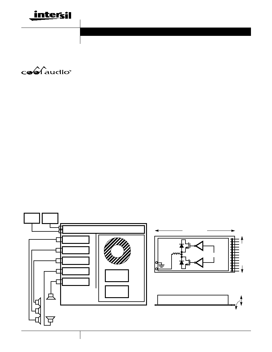
Reference Design Block Diagram
SOURCE
HCA600ACREF
HCA600ACREF
PRE-AMPLIFIER
HCA600ACREF
HCA600ACREF
PO
WER DISTRIB
UTION
SOURCE
HEATSINK / EMI SHIELD
HCA600ACREF
HCA8001
HCA600ACREF
HCA8001
27.9MM (1.1")
220MM (8.7")
78 MM (3.08")
FETS AND DIODES
POWER
SUPPLY
NOTE: The HCA600ACREF can be used in many different commercial and professional applications
including movie theater surround sound systems as depicted in this reference design block diagram.
1
2
Data Sheet
October 1999
2
Absolute Maximum Ratings
Operating Conditions
Bus Voltage, V
BUS
. . . . . . . . . . . . . . . . . . . . . . . . . . . . . ±
130V (Note 1)
+/-12V . . . . . . . . . . . . . . . . . . . . . . . . . . . . . . . . . . . . . . . . . . +/-15V
12VFLT. . . . . . . . . . . . . . . . . . . . . . . . . . . . . . . . . . . . . . . -Bus +15V
Audio Inputs . . . . . . . . . . . . . . 12V Differential Peak to Peak Voltage
NOTE:
1. WARNING: The voltages inside the shield, at the
edge connector, and on the speaker cables are
potentially deadly. Extreme caution is required.
Bus Voltage, V
BUS
. . . . . . . . . . . . . . . . . . . . . . . . . . . . . . . . . . . . . ±
110V
+/-12V . . . . . . . . . . . . . . . . . . . . . . . . . . . . . . . . . . . . . . . . . . +/-12V
12VFLT . . . . . . . . . . . . . . . . . . . . . . . . . . . . . . . . . . . . . . -Bus +12V
Ambient Temperature Range . . . . . . . . . . . . . . . . . . . . . 0
o
C to 50
o
C
CAUTION: Stresses above those listed in "Absolute Maximum Ratings" may cause permanent damage to the device. This is a stress only rating and operation of the
device at these or any other conditions above those indicated in the operational sections of this specification is not implied.
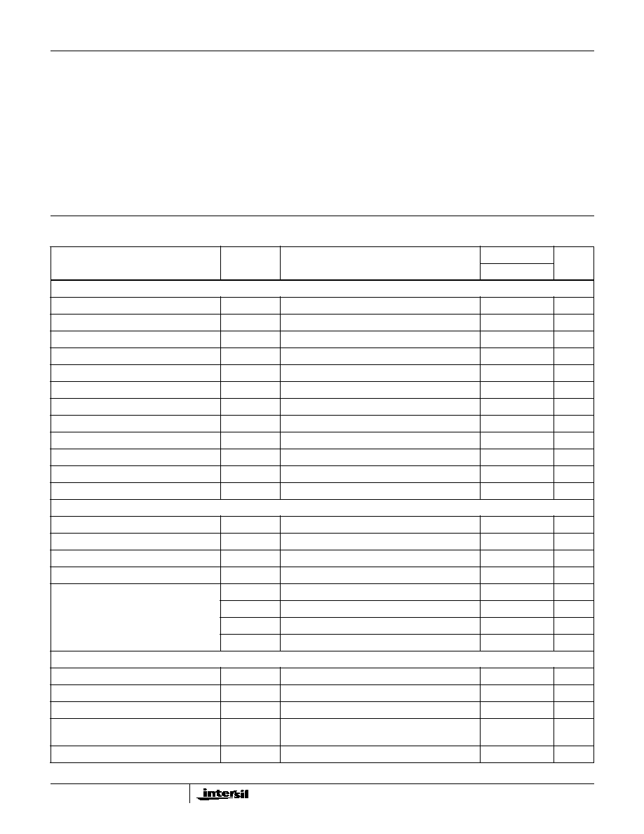
Electrical Specifications
R
LOAD
= 8
, V
BUS
=
±
110V, Supply Source Resistance < 2.5
, Storage Capacitor > 12,000
µ
F, 12VFLT = 12V,
+/-12V = +/-12V
PARAMETER
SYMBOL
TEST CONDITIONS
T
A
= 25
o
C
UNITS
TYP
SUPPLY SPECIFICATION
Minimum Bus Voltage
V
BUS MIN
600W into 8
±
110
V
±
V
BUS
RMS Current
I
V BUS
1kHz Sine Wave, Full Output Power (8
load)
3
A
±
V
BUS
RMS Current
I
V BUS
1kHz Sine Wave, Full Output Power (4
load)
6
A
±
V
BUS,Q
Average Current
I
VBUSQ
Quiescent Current, No Signal
60
mA
12V Float Current
I
12VFLTBIAS
Current supplied to power output gate driver circuitry
400
mA
Minimum +/-12V
V
BIASmin
1kHz Sine Wave, Full Output Power (8
load)
11.5
V
±
12V Max RMS Current
I+/-
15V
No input signal
40
mA
Rising Under Voltage Lock Out Voltage
V
UV Rising
Bus voltage that activates the amplifier
±
75
V
Falling Under Voltage Lock Out Voltage
V
UV Falling
Bus voltage that shuts down the amplifier
±
50
V
ENABLE Threshold Voltage
V
ENABLE1
Amplifier starts at this voltage, input amplifier muted
1
V
ENABLE Threshold Voltage
V
ENABLE2
Input amplifiers active and entire amplifier active
2
V
ENABLE Internal Source Current
I
ENABLE
Internal "Pull Up" Current
25
µ
A
OUTPUT POWER AND EFFICIENCY
Maximum Output Power (Note 2)
P
MAX8
THD = 1%, 1kHz, R
LOAD
= 8
600
W
Maximum Output Power (Note 2)
10% THD
8
THD = 10%, 1kHz, R
LOAD
= 8
800
W
Maximum Output Power (Note 2)
P
MAX4
THD = 1%, 1kHz, R
LOAD
= 4
1000
W
Maximum Output Power (Note 2)
10% THD
4
THD = 10%, 1kHz, R
LOAD
= 4
1200
W
Efficiency
PMAX
EFF
P
OUT
= 200W, 8
88
%
PMAX
EFF
P
OUT
= 500W, 8
95
%
PMAX
EFF
P
OUT
= 400W, 4
88
%
PMAX
EFF
P
OUT
= 1000W, 4
90
%
AMPLIFIER PERFORMANCE
Total Harmonic Distortion + Noise
THD+N
P
OUT
= 400W, R
LOAD
= 8
, 1kHz
0.015
%
Signal to Noise Ratio
V
SNR
Relative to full scale output, 600W into 8
110
dB
Output Noise
V
N
200
µ
V
Intermodulation Distortion
IMD
SMPTE, 60Hz and 7kHz, 4:1,
R
LOAD
= 8
at 25W Output
0.02
%
PSRR (
V
OUT
/
V
BUS
)
PSRR
DC
300
µ
V/V
HCA600ACREF
3
PSRR (
V
OUT
/
V
BUS
)
PSRRac
120Hz
-65
dB
Amplifier Output Offset Voltage
|V
OS
|
DC voltage across the speaker, load = 8
2
mV
Amplifier Output Impedance
Z
OUT
Measured at 1kHz and 10W Output
16
m
Damping Factor
DF
Measured at 1kHz and 10W Output
500
ADDITIONAL CHARACTERISTICS
Cutoff Frequency, Referenced to 1kHz
F
UPPER8
-3dB, R
LOAD
= 8
at 10W Output
80
kHz
Cutoff Frequency, Referenced to 1kHz
F
UPPER4
-3dB, R
LOAD
= 4
at 10W Output
70
kHz
20kHz Response, Referenced to 1kHz
F
R
at 20kHz
Output at 20kHz and 10W, R
LOAD
= 8
-0.5
dB
Power Bandwidth
P
BW
Maximum Frequency for Full Power R
LOAD
= 8
28
kHz
Slew Rate
SR
Maximum rate of change of the output voltage
18
V/
µ
s
Maximum Switching Ripple on Output
F
PWM
Full Output Power, R
LOAD
= 8
12.0
V
Input Gain
A
V
Either Inverting or non inverting input. Unused
input returned to analog ground
26
dB
Input Impedance, Inverting Input
R
-INPUT
Differential amplifier input, other input grounded
10
k
Input Impedance, Non Inverting Input
R
+INPUT
Differential amplifier input, other input grounded
5
k
Output Signal Phasing
Phasing
Positive going signal on non Inverting input
results in negative going amplifier output
180
Degrees
Over Temperature Shut Down
OT
SD
Rising temperature to shutdown amplifier.
Set by an external thermistor
110
o
C
Over Temperature Hysteresis
OT
H
Difference between rising and falling temperature
shut down and start up points
10
o
C
Amplifier Output Current Limit
I
L
Absolute Value
25
A
Amplifier Output Current Limit Time
(Note 3)
T
IL
Time the amplifier must be in current limiting before
shutdown
50
ms
NOTES:
2. At this power level, the soft clipping circuitry is beginning to activate. It functions to "round off" peaks rather than hard limit as in most linear
amplifiers. This helps to give this amplifier a pleasing sound during limiting. Moreover, this feature also makes the amplifier "sound louder".
3. This time allows the amplifier to reproduce large, sustained peaks without shutting down, yet is adequate to protect the amplifier output from
shorted speaker lines.
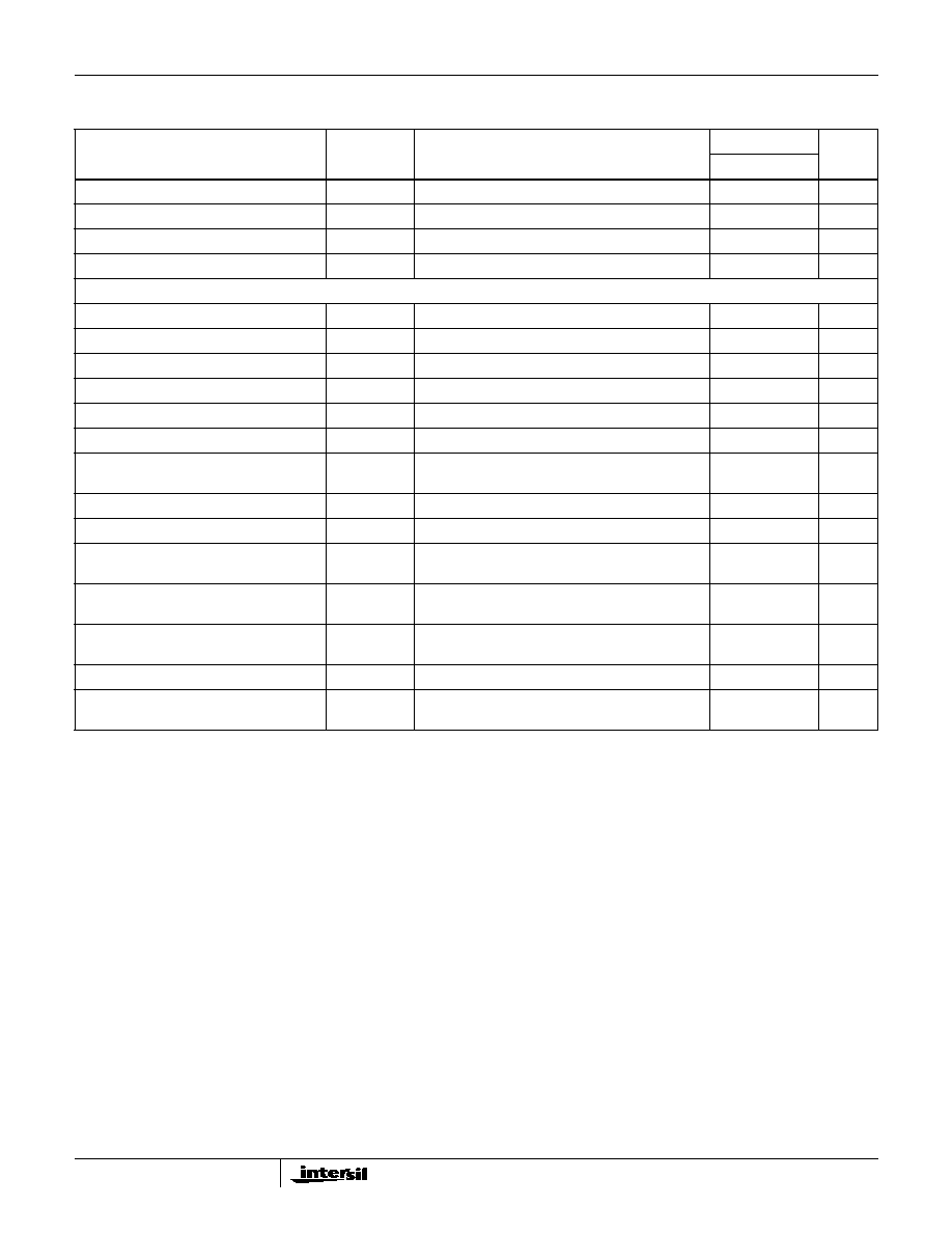
Electrical Specifications
R
LOAD
= 8
, V
BUS
=
±
110V, Supply Source Resistance < 2.5
, Storage Capacitor > 12,000
µ
F, 12VFLT = 12V,
+/-12V = +/-12V (Continued)
PARAMETER
SYMBOL
TEST CONDITIONS
T
A
= 25
o
C
UNITS
TYP
HCA600ACREF
4
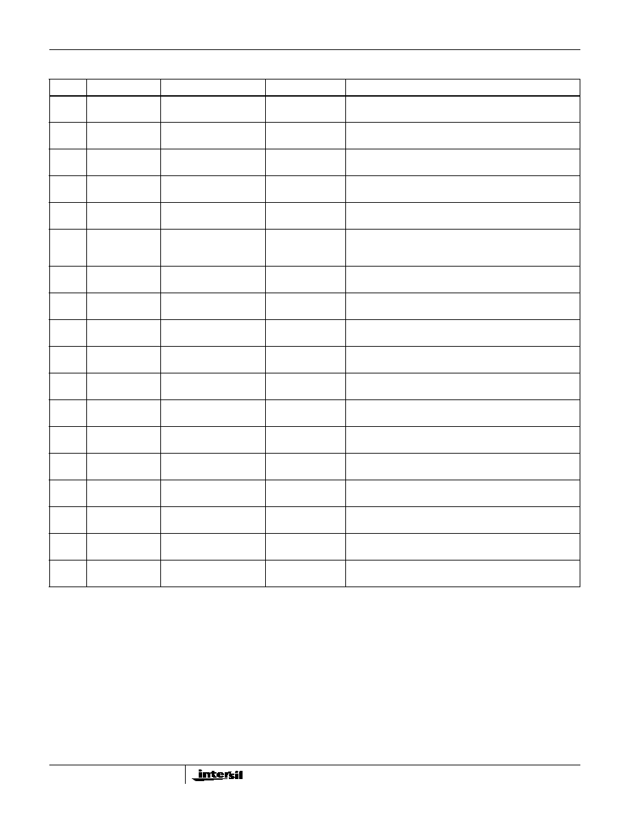
HCA600ACREF Connector Pin Designations
PIN
DESIGNATION
FUNCTION
WIRE COLOR
SPECIFICATIONS AND COMMENTS
1
Analog Ground
Input Ground
Black
(22 Gauge)
Connect to ground of pre-amp or connect to pin 18.
2
Non-Inv Input
Audio Input
Phono
Audio applied to pin 2 does not invert the phase of the signal.
Input impedance is 5k
.
3
Inv Input
Audio Input
Phono
Pin 3 and 4 are differential inputs. Audio applied to pin 3 inverts
the phase of the signal. Input impedance is 10k
.
4
Analog Ground
Input Ground
Black
(22 Gauge)
5
Enable
Enable
Green
(22 Gauge)
Add capacitance to delay startup or pull low to disable amp.
6
Fan
Controls fan or drives LED
indicating over temperature
shutdown
Brown
(22 Gauge)
Optional
7
CL_OUT
Drives LED to indicate
onset of current limit
Grey
(22 Gauge)
Optional
8
SFCL_OUT
Drives LED to indicate soft
clipping is activated
Blue
(22 Gauge)
Optional
9
-12V
- Bias Supply
Purple
(22 Gauge)
50mA, -12V
±
10%
10
+12V
+ Bias Supply
Orange
(22 Gauge)
50mA, +12V
±
10%
11
PGND
Power Ground
Black
(16 Gauge)
Connect to Star Ground
12
+BUS
Positive Supply
Red
(16 Gauge)
For best results use at least 12,000
µ
F, 160V electrolytic
capacitor. Limit Bus under no load conditions to 130V.
13
+BUS
Positive Supply
Red
(16 Gauge)
14
PGND
Power Ground
Black
(16 Gauge)
15
-BUS
Negative Supply
White
(16 Gauge)
For best results use at least 12,000
µ
F, 160V electrolytic
capacitor. Limit Bus under no load conditions to 130V.
16
-BUS
Negative Supply
White
(16 Gauge)
17
+12VFLT
Floating 12V supply
(referenced to -Bus)
Yellow
(20 Gauge)
500mA, +12V
±
10%
This signal is referenced to the negative rail (-Bus).
18
PGND
Power Ground
Black
(16 Gauge)
Molex Part Numbers: Header - 26-60-5180, Connector - 09-50-8183, Pins - 08-52-0113
WARNING: Insulate wires. Accidental shorts between +/- Bus and bias supplies will damage the amplifier.
HCA600ACREF
5
Typical Performance Curves
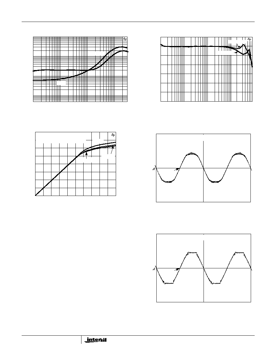
FIGURE 1. THD +N (%) vs FREQUENCY LOAD = 8
FIGURE 2. AMPLIFIER FREQUENCY RESPONSE
10W - LOAD = 8
FIGURE 3. AMPLIFIER TRANSFER CHARACTERISTIC WITH
VARIOUS SETTINGS OF SOFT CLIPPING
RESISTOR
FIGURE 4. OSCILLOSCOPE DISPLAY OF AMPLIFIER
OUTPUT WITH SOFT CLIPPING CIRCUIT
ENABLED
Soft Clipping
Figures 3, 4 and 5 show the effects of the soft clipping
circuitry within the amplifier. Figure 3 shows the transfer
characteristic of the amplifier for various values of the soft
clipping programming resistor. An important aspect of soft
clipping is the apparent increase in sound level. As soft
clipping is reached, the upper and lower envelop of the
sinewave is gradually reduced. This "soft" rounding reduces
the higher harmonics that would result if hard clipping as
shown in Figure 5 was enabled. Soft clipping also results in
an amplifier with a more pleasing sound. Figure 4 shows the
rounding of the output with soft clipping, while Figure 5
shows the ampler output without soft clipping.
FIGURE 5. OSCILLOSCOPE DISPLAY OF AMPLIFIER
OUTPUT WITH SOFT CLIPPING CIRCUIT
DISABLED
1
0.1
0.01
0.001
0.0005
10
100
1k
10k
30k
THD + N (%)
FREQUENCY (Hz)
400W
20W
10
100
1k
10k
80k
FREQUENCY (Hz)
1.000
0.0
-1.000
-2.000
-3.000
-4.000
-5.000
-6.000
AMPLIFIER OUTPUT (dBr)
LOAD = 4
LOAD = 8
0.0
13.0
26.0
39
52
65
78
90
0.0
0.6 0.12 0.18 2.4
3.0
3.6
4.2
4.8
5.2
6.0
1012
760
528
338
190
84
21
0.0
INPUT VOLTAGE (V
RMS
)
OUTPUT V
O
L
T
A
GE (V
RMS
)
OUTPUT PO
WER (W
RMS
)
LOAD = 8
AMPLIFIER OUTPUT vs INPUT
R = 20K
R = 10K
R =
100V/DIV
1ms/DIV
DSA 602A DIGITIZING SIGNAL ANALYZER
100V/DIV
1ms/DIV
DSA 602A DIGITIZING SIGNAL ANALYZER
HCA600ACREF