1
CAUTION: These devices are sensitive to electrostatic discharge; follow proper IC Handling Procedures.
VideolyzerTM is a trademark of Intersil Corporation. MacrovisionTM is a trademark of Macrovision Corporation.
http://www.intersil.com or 407-727-9207 | Copyright © Intersil Corporation 1999
HMP8117
NTSC/PAL Video Decoder
The HMP8117 is a high quality NTSC and PAL video
decoder with internal A/D converters. It is compatible with
NTSC M, PAL B, D, G, H, I, M, N, and combination N (N
C
)
video standards.
Both composite and S-video (Y/C) input formats are
supported. A 2-line comb filter plus a user-selectable
chrominance trap filter provide high quality Y/C separation.
User adjustments include brightness, contrast, saturation,
hue, and sharpness.
Vertical blanking interval (VBI) data, such as Closed
Captioning, Wide Screen Signalling and Teletext, may be
captured and output as BT.656 ancillary data. Closed
Captioning and Wide Screen Signalling information may also
be read out via the I
2
C interface.
The Videolyzer
TM
feature provides approved Macrovision
TM
copy-protection bypass and detection.
Features
∑ (M) NTSC and (B, D, G, H, I, M, N, N
C
) PAL Operation
- Optional Auto Detect of Video Standard
- ITU-R BT.601 (CCIR601) and Square Pixel Operation
∑ Videolyzer Feature
- MacrovisionTM Bypass and Detection
∑ Digital Anti-Alias Filter
∑ Power Down Mode
∑ Digital Output Formats
- VMI Compatible
- 8-bit, 16-bit 4:2:2 YCbCr
- 15-bit (5,5,5), 16-bit (5,6,5) RGB
- Linear or Gamma-Corrected
- 8-bit BT.656
∑ Analog Input Formats
- Three Analog Composite Inputs
- Analog Y/C (S-video) Input
∑ "Raw" (Oversampled) VBI Data Capture
∑ "Sliced" VBI Data Capture Capabilities
- Closed Captioning
- Widescreen Signalling (WSS)
- BT.653 System B, C and D Teletext
- North American Broadcast Teletext (NABTS)
- World System Teletext (WST)
∑ 2-Line (1H) Comb Filter Y/C Separator
∑ Fast I
2
C Interface
Applications
∑ Multimedia PCs
∑ Video Conferencing
∑ Video Compression Systems
∑ Video Security Systems
∑ LCD Projectors and Overhead Panels
∑ Related Products
- NTSC/PAL Encoders: HMP815x, HMP817x, HMP819x
- NTSC/PAL Decoders: HMP8112A, HMP8115
Ordering Information
PART NUMBER
TEMP RANGE
(
o
C)
PACKAGE
PACKAGE
NO.
HMP8117CN
0 to 70
80 Ld PQFP
Q80.14x20
HMPVIDEVAL/ISA
Evaluation Board: ISA Frame Grabber
NOTES:
1. PQFP is also known as QFP and MQFP.
2. Evaluation Board descriptions are in the Applications section.
Data Sheet
January 1999
File Number
4643

3
HMP8117
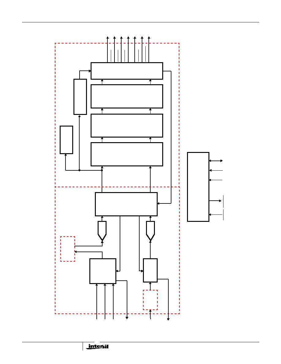
Analog Front End Block Diagram
LCAP
M
U
X
1.0
µ
F
VID1
VID2
Y_IN
1.0
µ
F
1.0
µ
F
CLAMP
CLAMP
75
7
6
5
CVBS2
CVBS1
CVBS3(Y)
1.75V
2X
76
0.1
µ
F
100
µ
A
100
µ
A
CHARGE PUMP
9
EXTERNAL
ANTI-ALIAS
FILTER
8
10-BIT
ADC
10
SYNC-TIP ENABLE
DIGITAL
ANTI-
ALIAS
13-STEP
VARIABLE
ATTENUATOR
FILTER
8-BIT
Y
OUT
Y[7:0]
Y
IN
LOW-PASS
FILTER
(REMOVE Fsc)
GAIN
CORRECTION
LOGIC
BACKPORCH
ENABLE
GAIN CONTROL
SET POINT
FINE ADJUST MULT. FACTOR
CORRECTION
MUL
TIPLIER
DISABLE
11
4
STORAGE
CAP
BUF
CHROMA
ATTEN
CHROMA
ATTEN
(BELOW)
CCAP
2X
29
C_IN
1.0
µ
F
C
19
75
EXTERNAL
ANTI-ALIAS
FILTER
17
10
A/D_TEST
BUF
DISCHARGE
CHARGE
100
µ
A
100
µ
A
CHARGE PUMP
DISCHARGE
CHARGE
BIAS/
INTERNAL
REFERENCE
0.1
µ
F
STORAGE
CAP
1.0
µ
F
78
28
RSET
REF_CAP
12.1K
C[7:0]
#
DECODER PIN #
MUX
SELECT
DIGITAL
ANTI-
ALIAS
FILTER
DISABLE
LUMA
DC-RESTORE
LOGIC
CHROMA
DC-RESTORE
LOGIC
CHROMA MULT.
(BELOW)
CHROMA
MULT.
(OFFSET LUMA SIGNAL TO LOWER ADC REF ~= 1.5V)
(OFFSET CHROMA SIGNAL TO ADC MID-SCALE ~= 2.0V)
CORRECTION
MUL
TIPLIER
7
NOMINAL (NTSC) OPERATING CONDITION
6
5
CVBSX. SIZE = INPUT. SYNC TIP CLAMPED AT ~= 1.75 VDC.
8
Y
OUT
/Y
IN
. SIZE = ~1.0 V
P-P
, SYNC TIP OFFSET ~= 1.5 VDC.
PIN #
19
C. SIZE = INPUT SIZE. PORCH OFFSET ~= 2.0 VDC.
17
A/D_TEST. SIZE ~= F(LUMA AGC), PORCH OFFSET ~= 2.0VDC.
9
CHROMA INPUT
76
NOMINAL (NTSC) OPERATING CONDITION
LCAP. DC-SIGNAL OFFSET ~= 2.4 VDC.
29
CCAP. DC-SIGNAL OFFSET ~= 2.4 VDC.
PIN #
28
RSET. DC-SIGNAL OFFSET ~= 1.2 VDC.
78
REF_CAP. DC-SIGNAL OFFSET ~= 2.5 VDC.
2.5V
1.5V
10-BIT
ADC
2.5V
1.5V
SYNC-TIP ENABLE
TR
UNCA
TE
8-BIT
TR
UNCA
TE
1.75V
(SIGNAL BIAS ~ 2.0V)
4 TO 13
DECODER
13
POWERDOWN
75
75
13-STEP
VARIABLE
ATTENUATOR
1.75V
TO
MUX
50
µ
A
REF
CLAMP
2.0V
1.0
µ
F
75
#
PIN
VAA
INPUT
VIDEO
nmos
(INTERNAL CLAMP)
(EXTERNAL)
+
-

5
Introduction
The HMP8117 is designed to decode baseband composite
or S-video NTSC and PAL signals, and convert them to
either digital YCbCr or RGB data. In addition to performing
the basic decoding operations, these devices include
hardware to decode different types of VBI data and to
generate full-screen blue, black and color bar patterns.
Digital PLLs are used to synchronize to all NTSC and PAL
standards. A chroma PLL is used to maintain color lock for
chroma demodulation while a line-locked PLL is used to
maintain vertical spatial alignment. The PLLs are designed
to maintain lock in the presence of VCR head switches, VCR
trick-mode and multi-path noise.
The HMP8117 provides the Videolyzer feature for
Macrovision (MV) copy-protection bypass and detection.
External Video Processing
Before a video signal can be digitized the decoder has some
external processing considerations that need to be
addressed. This section discusses those external aspects of
the HMP8117.
Analog Video Inputs
The HMP8117 supports either three composite or two
composite and one S-video input.
Three analog video inputs (CVBS 1-3) are used to select
which one of three composite video sources are to be
decoded. To support S-video applications, the Y channel
drives the CVBS3(Y) analog input, and the C channel drives
the C analog input.
The analog inputs must be AC-coupled to the video signals,
as shown in the Applications section.
Anti-alias Filters
Although a 23 tap digital halfband anti-alias filter is provided
for each A/D channel, an external passive filter is
recommended for optimum performance. The digital filter
has a flat response out to 5.4MHz with an approximate -3dB
bandwidth of 6.3MHz using a 27MHz input CLK2 sample
rate. For the CVBSx inputs, the filter is connected between
the YOUT and YIN pins. For the C (chroma) input, the anti-
alias filter should be connected before the C input.
Recommended filter configurations are shown on the
reference schematic in Figure 20. These filters have flat
response out to 4.2MHz with an approximate -3dB
bandwidth of 8MHz. If upgrading from the HMP8115 or
HMP8112A, the previous filter configurations may be used
but with slightly degraded bandwidth. Alternative higher or
lower performance filters configurations may substituted.
Digitization of Video
Prior to A/D conversion, the input signal is offset and scaled to
known video levels. After digitization, sample rate converters
and a comb filter are used to perform color separation and
demodulation.
A/D Conversion
Each CVBSX video input channel has a video clamp circuit
that is independent of PLL timing. The input clamp provides
a coarse signal offset to position the sync tip within the A/D
converter sampling range so that the AGC and DC-
RESTORE logic can operate.
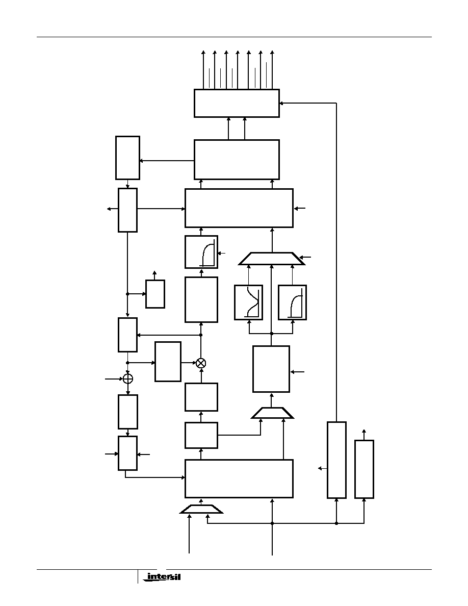
A/D Conversion
Video data is sampled at the CLK2 frequency then processed
by the input sample rate converter. The output levels of the
ADC after AGC and DC restoration processing are:
AGC and DC Restoration
The AGC amplifier attenuates or amplifies the analog video
signal to ensure that the blank level generates code 56 or 59
depending on the video standard. The difference from the
ideal blank level of 56 or 59 is used to control the amount of
attenuation or gain of the analog video signal. To obtain a
stable DC reference for the AGC, a digital low-pass filter
removes the chroma burst from the input signal's backporch.
DC restoration positions the video signal so that the sync tip
generates a code 0. The internal timing windows for AGC
and DC restoration are show in Figure 3. The appropriate
windows are automatically determined by the decoder when
the input signal is auto-detected or manually selected.
(M) NTSC
(M, N) PAL
(B, D, G, H, I, N
C
)
PAL
white
196
196
black
66
59
blank
56
59
sync
0
0
FIGURE 1. AGC AND DC RESTORE INTERNAL TIMING
VIDEO INPUT
DC RESTORE
AGC
HMP8117