9-6
August 1997
ICM7211, ICM7212
4-Digit, ICM7211 (LCD) and
ICM7212 (LED) Display Drivers
Features ICM7211 (LCD)
∑ Four Digit Non-Multiplexed 7 Segment LCD Display
Outputs with Backplane Driver
∑ Complete Onboard RC Oscillator to Generate Backplane
Frequency
∑ Backplane Input/Output Allows Simple Synchronization
of Slave-Devices to a Master
∑ ICM7211 Devices Provide Separate Digit Select Inputs to
Accept Multiplexed BCD Input (Pinout and Functionally
Compatible with Siliconix DF411)
∑ ICM7211M Devices Provide Data and Digit Address
Latches Controlled by Chip Select Inputs to Provide a
Direct High Speed Processor Interface
∑ ICM7211 Decodes Binary to Hexadecimal; ICM7211A
Decodes Binary to Code B (0-9, Dash, E, H, L, P, Blank)
∑ ICM7211A Available in Surface Mount Package
Features ICM7212AM (LED)
∑ 28 Current-Limited Segment Outputs Provide 4-Digit
Non-Multiplexed Direct LED Drive at >5mA Per Segment
∑ Brightness Input Allows Direct Control of LED
Segment Current with a Single Potentiometer or
Digitally as a Display Enable
∑ ICM7212AM Device Provides Same Input Configuration
and Output Decoding Options as the ICM7211AM
Description
The ICM7211 (LCD) and ICM7212 (LED) devices constitute
a family of non-multiplexed four-digit seven-segment CMOS
display decoder-drivers.
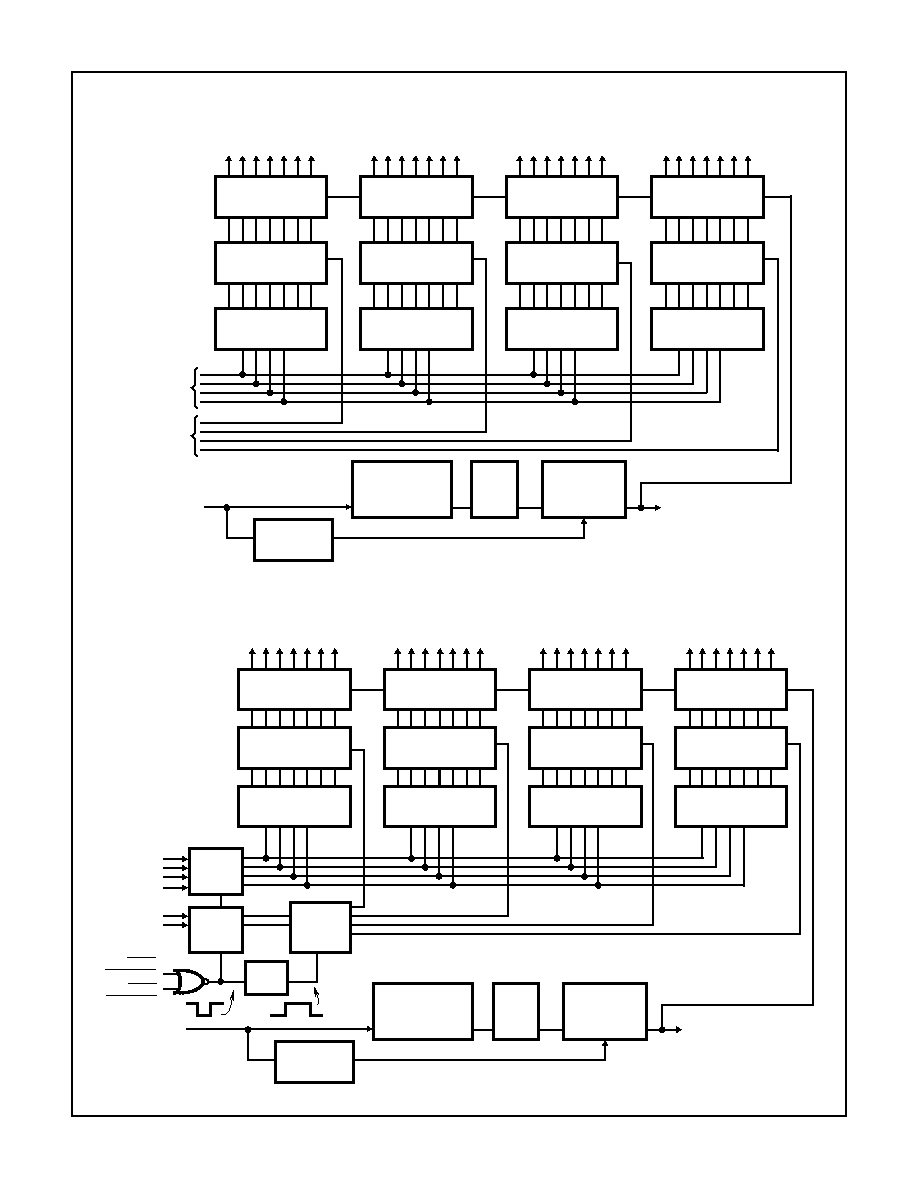
The ICM7211 devices are configured to drive conventional
LCD displays by providing a complete RC oscillator, divider
chain, backplane driver, and 28 segment outputs.
The ICM7212 devices are configured to drive common-
anode LED displays, providing 28 current-controlled, low
leakage, open-drain N-Channel outputs. These devices
provide a brightness input, which may be used at normal
logic levels as a display enable, or with a potentiometer as a
continuous display brightness control.
These devices are available with multiplexed or microproces-
sor input configurations. The multiplexed versions provide four
data inputs and four Digit Select inputs. This configuration is
suitable for interfacing with multiplexed BCD or binary output
devices, such as the ICM7217, ICM7226, and ICL7135. The
microprocessor versions provide data input latches and Digit
Address latches under control of high-speed Chip Select
inputs. These devices simplify the task of implementing a
cost-effective alphanumeric seven-segment display for micro-
processor systems, without requiring extensive ROM or CPU
time for decoding and display updating.
The standard devices will provide two different decoder
configurations. The basic device will decode the four bit
binary inputs into a seven-segment alphanumeric hexadeci-
mal output. The "A" versions will provide the "Code B" output
code, i.e., 0-9, dash, E, H, L, P, blank. Either device will cor-
rectly decode true BCD to seven-segment decimal outputs.
Ordering Information
PART NUMBER
DISPLAY
TYPE
DISPLAY
DECODING
INPUT
INTERFACING
DISPLAY DRIVE
TYPE
TEMP.
RANGE (
o
C)
PACKAGE
PKG. NO.
ICM7211lPL
LCD
Hexadecimal
Multiplexed
Direct Drive
-40 to 85
40 Ld PDIP
E40.6
ICM7211MlPL
LCD
Hexadecimal
Microprocessor
Direct Drive
-40 to 85
40 Ld PDIP
E40.6
ICM7211AlPL
LCD
Code B
Multiplexed
Direct Drive
-40 to 85
40 Ld PDIP
E40.6
ICM7211AMlPL
LCD
Code B
Microprocessor
Direct Drive
-40 to 85
40 Ld PDIP
E40.6
ICM7211AlM44
LCD
Code B
Multiplexed
Direct Drive
-40 to 85
44 Ld MQFP
Q44.10x10
ICM7211AMlM44
LCD
Code B
Microprocessor
Direct Drive
-40 to 85
44 Ld MQFP
Q44.10x10
ICM7212AMlPL
LED
Code B
Microprocessor
Common Anode
-40 to 85
40 Ld PDIP
E40.6
File Number
3158.1
CAUTION: These devices are sensitive to electrostatic discharge; follow proper IC Handling Procedures.
http://www.intersil.com or 407-727-9207
|
Copyright
©
Intersil Corporation 1999