
Preliminary
1
64Mb SDRAM
Ascend Semiconductor Corporation
ASCEND
Semiconductor
64M SDRAM
Data sheet
ASCEND
Semiconductor
64M SDRAM
Data sheet
Tel: (03)5635888 / Fax: (03)5635188/ http://www.ascendsemi.com.tw

Preliminary
2
64Mb SDRAM
Ascend Semiconductor Corporation
Ordering Information
AD 48 4M 16 4 4 V T A ≠ 7 L I
Ascend
Semiconductor
EDO
: 40
FPM
: 41
DDRSDRAM
: 42
DDRSGRAM
: 43
SGRAM
: 46
SDRAM
: 48
Power
Non : Standard
L : Low power
Density
16M : 16 Mega Bits
8M : 8 Mega Bits
4M : 4 Mega Bits
2M : 2 Mega Bits
1M : 1 Mega Bit
Refresh
1 : 1K, 8 : 8K
2 : 2K, 6 :16K
4 : 4K
Bank
2 : 2Bank 6 : 16Bank
4 : 4Bank 3 : 32Bank
8 : 8Bank
Revision
A : 1st B : 2nd
C : 3rd D :4th
Interface
V: 3.3V
R: 2.5V
Package
Min Cycle Time ( Max Freq.)
-55 : 5.5ns ( 183MHz )
-6 : 6ns ( 167MHz )
-7 : 7ns ( 143MHz )
-8 : 8ns ( 125MHz )
-10 : 10ns ( 100MHz )
-15 : 15ns (66MHz,CL1 applicable)
C: CSP B: uBGA
T: TSOP Q: TQFP
P: PQFP ( QFP )
Organization
8 : x8
9 : x9
16 : x16
18 : x18
32 : x32
Operating Range
I : Industrial
-40
~ 85
Non : Commercial
0
~ 70
S : Special
0
~ 85

Preliminary
3
64Mb SDRAM
Ascend Semiconductor Corporation
Features
∑
Fully synchronous to positive clock edge
∑ Single 3.3V +/- 0.3V power supply
∑ LVTTL compatible with multiplexed address
∑ Industrial temperature available
∑ Programmable Burst Length ( BL ) - 1,2,4,8 or full page
∑ Programmable CAS Latency ( CL ) -1, 2 or 3
∑ Data Mask ( DQM ) for Read/Write masking
∑ Programmable wrap sequential - Sequential ( BL = 1/2/4/8/full page )
- Interleave ( BL = 1/2/4/8 )
∑ Burst read with single-bit write operation
∑ All inputs are sampled at the positive rising edge of the system clock.
∑ Auto refresh and self refresh
∑ 4,096 refresh cycles / 64ms
Ordering Information
Description
The AD484M1644VTA is Synchronous Dynamic Random Access Memory ( SDRAM )
organized as 1,048,756 words x 4 banks x 16 bits. All inputs and outputs are synchronized
with the positive edge of the clock . The 64Mb SDRAM uses synchronized pipelined
architecture to achieve high speed data transfer rates and is designed to operate in 3.3V
low power memory system. It also provides auto refresh with power saving / down mode.
All inputs and outputs voltage levels are compatible with LVTTL .
64Mb( 4Banks ) Synchronous DRAM
AD484M1644VTA ( 4Mx16 )
* Ascend Semiconductor reserves the right to change products or specification without notice.
CL1
Note
Low power
Low power
Low power
Standard
Standard
Standard
Standard
Power
Commercial Range : 0
~ 70
Commercial Range : 0
~ 70
Commercial Range : 0
~ 70
Commercial Range : 0
~ 70
Commercial Range : 0
~ 70
Commercial Range : 0
~ 70
Commercial Range : 0
~ 70
Operation Range
54pins,
TSOPII
54pins,
TSOPII
54pins,
TSOPII
54pins,
TSOPII
54pins,
TSOPII
54pins,
TSOPII
54pins,
TSOPII
Package
100MHz
125MHz
143MHz
66MHz
143MHz
167MHz
183MHz
Max
Freg.
AD484M1644VTA-10L
AD484M1644VTA-8L
AD484M1644VTA-7L
AD484M1644VTA-15
AD484M1644VTA-7
AD484M1644VTA-6
AD484M1644VTA-55
Part number
Preliminary
4
64Mb SDRAM
Ascend Semiconductor Corporation
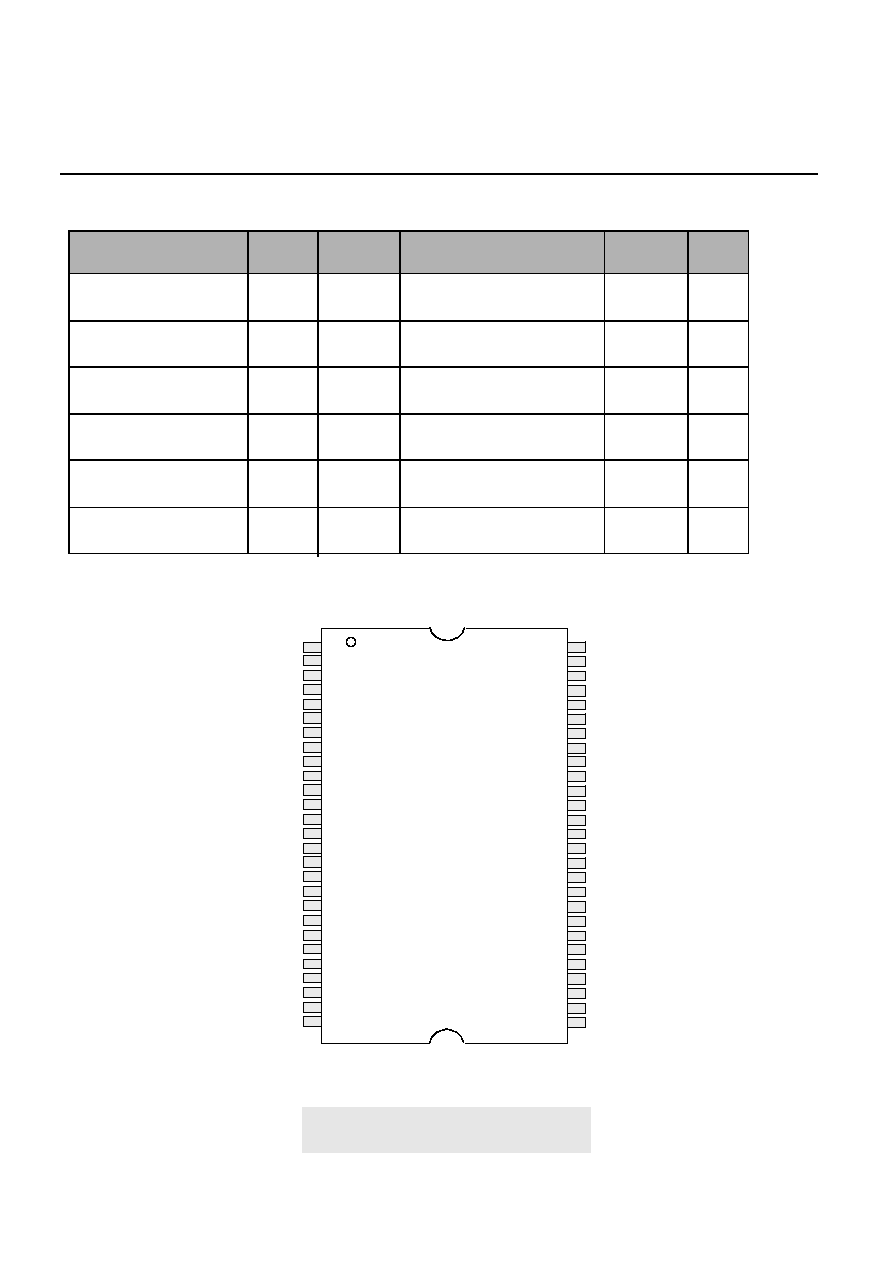
54pin TSOP-II
(400milx875mil)
(0.8mm Pin pitch)
Pin Assignment ( Top View )
1
2
3
4
5
6
7
8
9
10
11
12
13
14
15
16
17
18
19
20
21
22
23
24
25
26
27
V
DD
DQ0
V
DDQ
DQ1
DQ2
V
SSQ
DQ3
DQ4
V
DDQ
DQ5
DQ6
V
SSQ
DQ7
V
DD
LDQM
/WE
/CAS
/RAS
/CS
BA0
BA1
A10/AP
A0
A1
A2
A3
V
DD
V
SS
DQ15
V
SSQ
DQ14
DQ13
V
DDQ
DQ12
DQ11
V
SSQ
DQ10
DQ9
V
DDQ
DQ8
V
SS
NC
UDQM
CLK
CKE
NC
A11
A9
A8
A7
A6
A5
A4
V
SS
54
53
52
51
50
49
48
47
46
45
44
43
42
41
40
39
38
37
36
35
34
33
32
31
30
29
28
1
2
3
4
5
6
7
8
9
10
11
12
13
14
15
16
17
18
19
20
21
22
23
24
25
26
27
Ordering Information
* Ascend Semiconductor reserves the right to change products or specification without notice.
Note
Low power
Low power
Low power
Standard
Standard
Standard
Power
Industrial Range : -40
~ 85
Industrial Range : -40
~ 85
Industrial Range : -40
~ 85
Industrial Range : -40
~ 85
Industrial Range : -40
~ 85
Industrial Range : -40
~ 85
Operation Range
54pins,
TSOPII
54pins,
TSOPII
54pins,
TSOPII
54pins,
TSOPII
54pins,
TSOPII
54pins,
TSOPII
Package
100MHz
125MHz
143MHz
100MHz
125MHz
143MHz
Max
Freg.
AD484M1644VTA-10LI
AD484M1644VTA-8LI
AD484M1644VTA-7LI
AD484M1644VTA-10I
AD484M1644VTA-8I
AD484M1644VTA-7I
Part number

Preliminary
5
64Mb SDRAM
Ascend Semiconductor Corporation
Pin
Name
Pin Function
CLK
System Clock
Master Clock Input(Active on the Positive rising edge)
/CS
Chip select
Selects chip when active
CKE
Clock Enable
Activates the CLK when "H" and deactivates when "L".
CKE should be enabled at least one cycle prior to new
command. Disable input buffers for power down in standby.
A0 ~ A11
Address
Row address (A0 to A11) is determined by A0 to A11 level
at the bank active command cycle CLK rising edge.
CA(CA0 to CA7) is determined by A0 to A7 level at the
read or write command cycle CLK rising edge.
And this column address becomes burst access start
address. A10 defines the pre-charge mode. When A10 = High
at the pre-charge command cycle, all banks are pre-charged.
But when A10 = Low at the pre-charge command cycle,
only the bank that is selected by BA0/BA1 is pre-charged.
/RAS
Row address strobe
Latches Row Addresses on the positive rising edge of the
CLK with /RAS "L". Enables row access & pre-charge.
/CAS
Column address strobe
Latches Column Addresses on the positive rising edge of the
CLK with /CAS low. Enables column access.
/WE
Write Enable
Latches Column Addresses on the positive rising edge of the
CLK with /CAS low. Enables column access.
LDQM/ UDQM
Data input/output Mask
DQM controls I/O buffers.
DQ0 ~ 15
Data input/output
DQ pins have the same function as I/O pins on a conventional
DRAM.
V
DD
/V
SS
Power supply/Ground
V
DD
and V
SS
are power supply pins for internal circuits.
Pin Descriptions ( Simplified )
BA0, BA1
Bank Address
Selects which bank is to be active.
NC
No connection
This pin is recommended to be left No Connection on the
device.
V
DDQ
/V
SSQ
Power supply/Ground
V
DDQ
and V
SSQ
are power supply pins for the output buffers.
Preliminary
6
64Mb SDRAM
Ascend Semiconductor Corporation
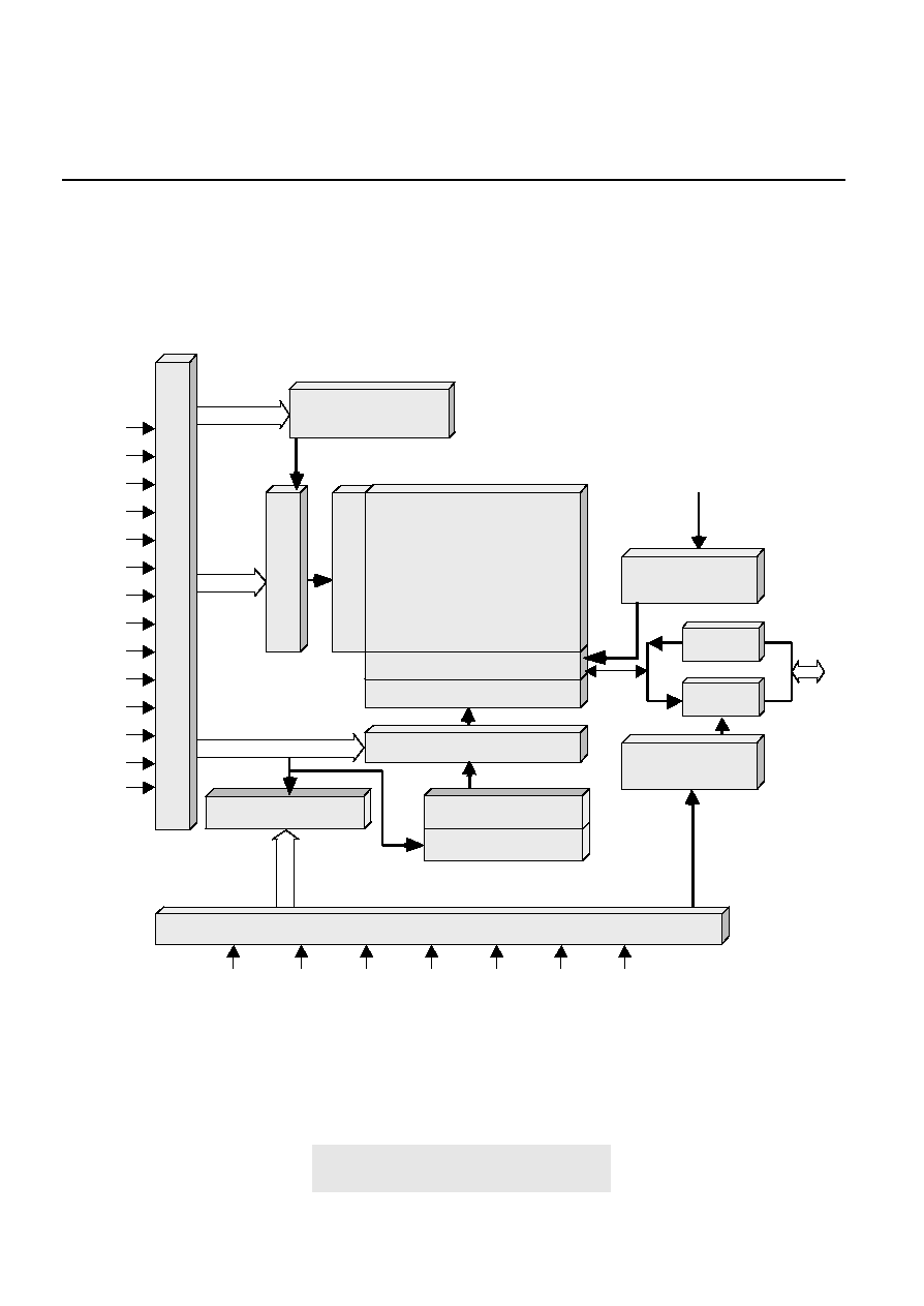
Burst Counter
Row Add. Buffer
Col. Add. Buffer
Col. Decoder
S/A & I/O gating
Block Diagram
A0
A1
A2
A3
A4
A5
A6
A7
A8
A9
A10
A11
BA0
BA1
Timing Register
CKE /CS /RAS /CAS /WE DQM
Row Decoder
Memory
Array
Address Register
Mode Register Set
Auto/Self
Refresh Counter
Col. Add. Counter
Write DQM
Control
Data In
Data Out
Read DQM
Control
DQi
DQM
DQM
CLK
/CLK

Preliminary
7
64Mb SDRAM
Ascend Semiconductor Corporation
IDLE
Row
Active
Active
Power
Down
Power
Down
CBR
Refresh
Self
Refresh
Mode
Register
Set
WRITE
WRITEA
READ
READA
READ
Suspend
READA
Suspend
WRITE
Suspend
WRITEA
Suspend
Precharge
POWER
ON
Simplified State Diagram
SELF
SELF Exit
REF
MRS
CKE
CKE
ACT
CKE
CKE
BST
Read
Read
CKE
CKE
CKE
CKE
Write
Read
Write with
Read with
CKE
CKE
CKE
CKE
Precharge
PRE
PRE
Write
Manual Input
Automatic Sequence

Preliminary
8
64Mb SDRAM
Ascend Semiconductor Corporation
BA1 BA0
A10 A9
A8
A7
A6
A5
A4
A3
A2
A1
A0
Operation Mode
CAS Latency
BT
Burst Length
A2
A1
A0
Sequential
Burst Length
Interleave
0
0
0
1
1
0
0
1
2
2
0
1
0
4
4
0
1
1
8
8
1
0
0
Reserved Reserved
1
0
1
Reserved Reserved
1
1
0
Reserved Reserved
1
1
1
Full Page
Reserved
A3
0
Burst Type
Sequential
1
Interleave
A6
A5
A4
CAS Latency
0
0
0
Reserved
0
0
1
1
0
1
0
2
0
1
1
3
1
0
0
Reserved
1
0
1
Reserved
1
1
0
Reserved
1
1
1
Reserved
BA1
BA0
A10
A9
A8
A7
0
0
0
0
0
0
0
0
0
1
0
0
Operation Mode
Normal
Burst read with Single-bit Write
Address Input for Mode Register Set
A11
A11
0
0

Preliminary
9
64Mb SDRAM
Ascend Semiconductor Corporation
A2 A1 A0
Interleave Addressing
Burst Length
X X 0
0 1
2
X X 1
1 0
X 0 0
0 1 2 3
4
X 0 1
1 0 3 2
X 1 0
2 3 0 1
X 1 1
3 2 1 0
0 0 0
0 1 2 3 4 5 6 7
8
0 0 1
1 0 3 2 5 4 7 6
Burst Type ( A3 )
Sequential Addressing
0 1
1 0
0 1 2 3
1 2 3 0
2 3 0 1
3 0 1 2
0 1 2 3 4 5 6 7
1 2 3 4 5 6 7 0
0 1 0
2 3 0 1 6 7 4 5
0 1 1
3 2 1 0 7 6 5 4
1 0 0
4 5 6 7 0 1 2 3
1 0 1
5 4 7 6 1 0 3 2
1 1 0
6 7 4 5 2 3 0 1
1 1 1
7 6 5 4 3 2 1 0
n n n
-
2 3 4 5 6 7 0 1
3 4 5 6 7 0 1 2
4 5 6 7 0 1 2 3
5 6 7 0 1 2 3 4
6 7 0 1 2 3 4 5
7 0 1 2 3 4 5 6
Cn Cn+
1
Cn+
2
... ...
Full Page *
* Page length is a function of I/O organization and column addressing
x32 (CA0 ~ CA7) : Full page = 256 bits

Preliminary
10
64Mb SDRAM
Ascend Semiconductor Corporation
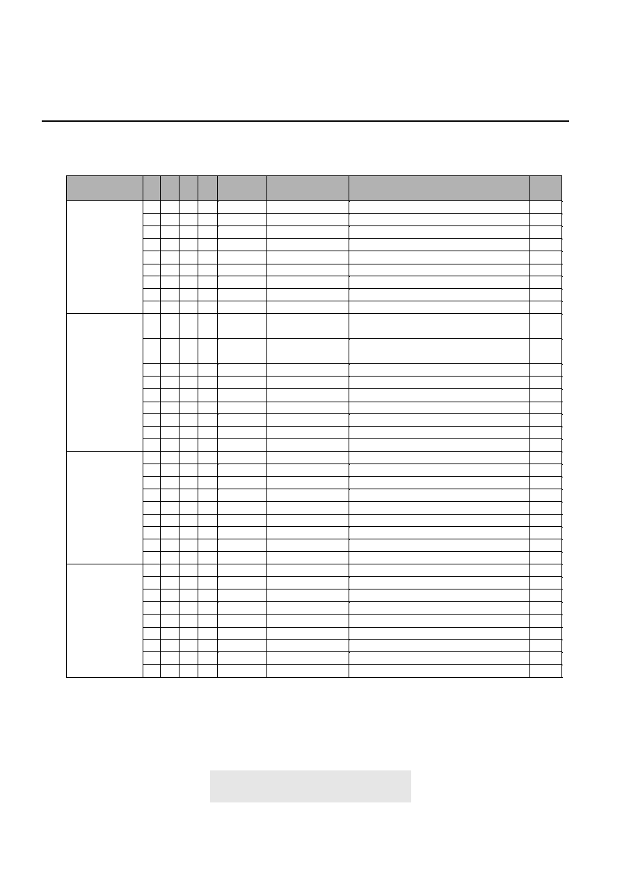
Command
Symbol
CKE
Ignore Command
DESL
No operation
NOP
Truth Table
1. Command Truth Table ( AD484M1644VTA )
H
H
X
n-1
n
/CS
H
L
X
/RAS
X
H
/CAS
X
H
/WE
X
H
BA0,
BA1
X
X
A10
X
X
A11,
A9~A0
X
X
Burst stop
BSTH
Read
READ
H
H
X
L
L
X
H
H
H
L
L
H
X
V
X
L
X
V
Read with auto pre-charge
READA
Write
WRIT
H
H
X
L
L
X
H
H
L
L
H
L
V
V
H
L
V
V
Write with auto pre-charge
WRITA
Bank activate
ACT
H
H
X
L
L
X
L
L
H
H
H
H
V
V
H
V
V
V
Pre-charge select bank
PRE
H
L
X
L
H
L
V
L
X
Pre-charge all banks
PALL
Mode register set
MRS
H
H
X
L
L
X
L
L
H
L
L
L
X
L
H
L
X
V
Note : H = High level, L = Low level, X = High or Low level (Don't care), V = Valid data input
Command
Symbol
CKE
Data write / output enable
ENB
Data mask / output disable
MASK
2. DQM Truth Table
H
H
X
n-1
n
/CS
H
L
X
Upper byte write enable / output enable
BSTH
Read
READ
H
H
X
L
L
X
Read with auto pre-charge
READA
Write
WRIT
H
H
X
L
L
X
Write with auto pre-charge
WRITA
Bank activate
ACT
H
H
X
L
L
X
Pre-charge select bank
PRE
H
L
X
Pre-charge all banks
PALL
Mode register set
MRS
H
H
X
L
L
X
Note : H = High level, L = Low level, X = High or Low level (Don't care), V = Valid data input
Command
Symbol
CKE
Activating
Any
3. CKE Truth Table
H
L
L
n-1
n
/CS
X
X
L
/RAS
X
X
/CAS
X
X
/WE
X
X
Addr.
X
X
Clock suspend
Idle
REF
L
H
H
X
L
H
X
L
X
L
X
H
X
X
Idle
SELF
Self refresh
H
L
L
L
L
H
L
H
L
H
H
H
X
X
Idle
Power down
H
L
L
X
X
H
X
X
X
X
X
X
X
X
Remark H = High level, L = Low level, X = High or Low level (Don't care)
Command
Clock suspend mode entry
Clock suspend mode
Clock suspend mode exit
CBR refresh command
Self refresh entry
Self refresh exit
Power down entry
Power down exit
L
H
H
X
X
X
X

Preliminary
11
64Mb SDRAM
Ascend Semiconductor Corporation
Current
state
Addr.
Idle
X
X
4. Operative Command Table
Action
Nop or power down
Nop or power down
Notes
2
2
BA/CA/A10
BA/CA/A10
ILLEGAL
ILLEGAL
3
3
BA/RA
Row activating
BA, A10
X
Nop
Refresh or self refresh
4
Remark H = High level, L = Low level, X = High or Low level (Don't care)
/CS
H
L
/R
X
H
/C
X
H
/W
X
X
L
L
H
H
L
L
H
L
L
L
H
H
L
L
L
L
H
L
L
H
Command
DESL
NOP or BST
READ/READA
WRIT/WRITA
ACT
PRE/PALL
REF/SELF
Op-Code
Mode register accessing
L
L
L
L
MRS
Row active
X
X
Nop
Nop
BA/CA/A10
BA/CA/A10
Begin read : Determine AP
Begin write : Determine AP
5
5
BA/RA
ILLEGAL
3
BA, A10
X
Precharge
ILLEGAL
6
4
H
L
X
H
X
H
X
X
L
L
H
H
L
L
H
L
L
L
H
H
L
L
L
L
H
L
L
H
DESL
NOP or BST
READ/READA
WRIT/WRITA
ACT
PRE/PALL
REF/SELF
Op-Code
ILLEGAL
L
L
L
L
MRS
Read
X
X
Continue burst to end
Row active
Continue burst to end
Row active
X
BA/CA/A10
Burst stop
Row active
Terminate burst, new read : Determine AP
7
BA/CA/A10
Terminate burst, start write : Determine AP
7, 8
BA/RA
BA/A10
ILLEGAL
Terminate burst, pre-charging
3
4
H
L
X
H
X
H
X
H
L
L
H
H
H
L
L
H
L
L
L
L
L
L
L
L
H
H
H
L
DESL
NOP
BST
READ/READA
WRIT/WRITA
ACT
PRE/PALL
X
ILLEGAL
L
L
L
H
REF/SELF
Write
X
X
Continue burst to end
Write recovering
Continue burst to end
Write recovering
X
BA/CA/A10
Burst stop
Row active
Terminate burst, start read : Determine AP 7, 8
7,8
BA/CA/A10
Terminate burst, new write : Determine AP 7
7
BA/RA
BA/A10
ILLEGAL
Terminate burst, pre-charging
3
9
H
L
X
H
X
H
X
H
L
L
H
H
H
L
L
H
L
L
L
L
L
L
L
L
H
H
H
L
DESL
NOP
BST
READ/READA
WRIT/WRITA
ACT
PRE/PALL
X
ILLEGAL
L
L
L
H
REF/SELF
Op-Code
ILLEGAL
L
L
L
L
MRS
Op-Code
ILLEGAL
L
L
L
L
MRS
Preliminary
12
64Mb SDRAM
Ascend Semiconductor Corporation
Current
state
Addr.
Read with AP
X
X
Action
Continue burst to end
Precharging
Continue burst to end
Precharging
Notes
X
BA/CA/A10
ILLEGAL
ILLEGAL
3
BA/RA
ILLEGAL
3
BA, A10
X
ILLEGAL
ILLEGAL
3
Remark H = High level, L = Low level, X = High or Low level (Don't care), AP = Auto Precharge
/CS
H
L
/R
X
H
/C
X
H
/W
X
H
L
L
H
H
H
L
L
H
L
L
H
H
L
L
L
L
H
L
L
H
Command
DESL
NOP
BST
READ/READA
ACT
PRE/PALL
REF/SELF
Op-Code
ILLEGAL
L
L
L
L
MRS
BA/CA/A10
ILLEGAL
3
L
H
L
L
WRIT/WRITA
Write with AP
X
X
burst to end
Write
recovering with auto precharge
Continue burst to end
Write
recovering with auto precharge
X
BA/CA/A10
ILLEGAL
ILLEGAL
3
BA/RA
ILLEGAL
3
BA, A10
X
ILLEGAL
ILLEGAL
3
H
L
X
H
X
H
X
H
L
L
H
H
H
L
L
H
L
L
H
H
L
L
L
L
H
L
L
H
DESL
NOP
BST
READ/READA
ACT
PRE/PALL
REF/SELF
Op-Code
ILLEGAL
L
L
L
L
MRS
BA/CA/A10
ILLEGAL
3
L
H
L
L
WRIT/WRITA
Precharging
X
X
Nop
Enter idle after t
RP
Nop
Enter idle after t
RP
X
BA/CA/A10
ILLEGAL
ILLEGAL
3
BA/RA
ILLEGAL
3
BA, A10
X
Nop
Enter idle after t
RP
ILLEGAL
H
L
X
H
X
H
X
H
L
L
H
H
H
L
L
H
L
L
H
H
L
L
L
L
H
L
L
H
DESL
NOP
BST
READ/READA
ACT
PRE/PALL
REF/SELF
Op-Code
ILLEGAL
L
L
L
L
MRS
BA/CA/A10
ILLEGAL
3
L
H
L
L
WRIT/WRITA
Row activating
X
X
Nop
Enter idle after t
RCD
Nop
Enter idle after t
RCD
X
BA/CA/A10
ILLEGAL
ILLEGAL
3
BA/RA
ILLEGAL
3,10
BA, A10
X
ILLEGAL
ILLEGAL
3
H
L
X
H
X
H
X
H
L
L
H
H
H
L
L
H
L
L
H
H
L
L
L
L
H
L
L
H
DESL
NOP
BST
READ/READA
ACT
PRE/PALL
REF/SELF
Op-Code
ILLEGAL
L
L
L
L
MRS
BA/CA/A10
ILLEGAL
3
L
H
L
L
WRIT/WRITA

Preliminary
13
64Mb SDRAM
Ascend Semiconductor Corporation
Current
state
Addr.
Write recovering
X
X
Action
Nop
Enter row active after t
DPL
Nop
Enter row active after t
DPL
Notes
X
BA/CA/A10
Nop
Enter row active after t
DPL
Start read, Determine AP
BA/RA
ILLEGAL
3
BA, A10
X
ILLEGAL
ILLEGAL
3
Remark H = High level, L = Low level, X = High or Low level (Don't care), AP = Auto Precharge
/CS
H
L
/R
X
H
/C
X
H
/W
X
H
L
L
H
H
H
L
L
H
L
L
H
H
L
L
L
L
H
L
L
H
Command
DESL
NOP
BST
READ/READA
ACT
PRE/PALL
REF/SELF
Op-Code
ILLEGAL
L
L
L
L
MRS
BA/CA/A10
New write, Determine AP
8
L
H
L
L
WRIT/WRITA
Write recovering
with AP
X
X
Nop
Enter precharge after t
DPL
Nop
Enter precharge after t
DPL
X
BA/CA/A10
Nop
Enter precharge after t
DPL
ILLEGAL
3,8
BA/RA
ILLEGAL
3
BA, A10
X
ILLEGAL
ILLEGAL
H
L
X
H
X
H
X
H
L
L
H
H
H
L
L
H
L
L
H
H
L
L
L
L
H
L
L
H
DESL
NOP
BST
READ/READA
ACT
PRE/PALL
REF/SELF
Op-Code
ILLEGAL
L
L
L
L
MRS
BA/CA/A10
ILLEGAL
3
L
H
L
L
WRIT/WRITA
Refreshing
X
X
Nop
Enter idle after t
RC
Nop
Enter idle after t
RC
X
X
ILLEGAL
ILLEGAL
H
L
X
H
X
H
X
X
L
L
H
L
L
H
X
X
DESL
NOP/ BST
READ/WRIT
ACT/PRE/PALL
X
ILLEGAL
L
L
L
X
REF/SELF/MRS
Mode Register
Accessing
X
X
Nop
Nop
X
X
ILLEGAL
ILLEGAL
H
L
X
H
X
H
X
H
L
L
H
H
H
L
L
X
DESL
NOP
BST
READ/WRIT
X
ILLEGAL
L
L
X
X
ACT/PRE/PALL/
REF/SELF/MRS
Notes 1. All entries assume that CKE was active (High level) during the preceding clock cycle.
2. If all banks are idle, and CKE is inactive (Low level), SDRAM will enter Power down mode.
All input buffers except CKE will be disabled.
3. Illegal to bank in specified states;
Function may be legal in the bank indicated by Bank Address (BA), depending on the state of that bank.
4. If all banks are idle, and CKE is inactive (Low level), SDRAM will enter Self refresh mode.
All input buffers except CKE will be disabled.
5. Illegal if t
RCD
is not satisfied.
6. Illegal if t
RAS
is not satisfied.
7. Must satisfy burst interrupt condition.
8. Must satisfy bus contention, bus turn around, and/or write recov ery requirements.
9. Must mask preceding data which don't satisfy t
DPL
.
10. Illegal if t
RRD
is not satisfied.

Preliminary
14
64Mb SDRAM
Ascend Semiconductor Corporation
Current
state
Addr.
Self refresh
X
X
5. Command Truth Table for CKE
Action
INVALID, CLK (n ≠ 1) would exit self refresh
Self refresh recovery
Notes
X
X
Self refresh recovery
ILLEGAL
X
ILLEGAL
X
Maintain self refresh
Remark : H = High level, L = Low level, X = High or Low level (Don't care)
/CS
X
H
/R
X
X
/C
X
X
/W
X
X
L
L
H
H
H
L
X
X
L
L
X
X
X
X
X
X
Self refresh
recovery
X
X
Idle after t
RC
Idle after t
RC
X
X
ILLEGAL
ILLEGAL
X
ILLEGAL
X
X
ILLEGAL
ILLEGAL
H
L
X
H
X
H
X
X
L
L
H
L
L
X
X
X
H
X
X
X
L
L
H
H
H
L
X
X
X
ILLEGAL
L
L
X
X
Both banks
idle
Refer to operations in Operative Command Table
Refer to operations in Operative Command Table
Refer to operations in Operative Command Table
X
Refresh
Op-Code
Refer to operations in Operative Command Table
Refer to operations in Operative Command Table
H
L
X
H
X
X
X
X
L
L
H
X
L
L
L
H
L
H
L
X
L
X
L
X
Refer to operations in Operative Command Table
L
H
X
X
Refer to operations in Operative Command Table
L
L
H
X
n-1
H
L
L
L
L
L
H
H
H
H
H
H
H
H
H
H
H
H
H
H
H
H
n
X
H
H
H
H
L
H
H
H
H
L
L
L
L
H
H
H
H
H
L
L
L
CKE
Power down
X
X
INVALID, CLK(n-1) would exit power down
Exit power down
Idle
X
Maintain power down mode
X
X
X
X
X
X
X
X
X
X
X
X
H
L
L
X
H
L
X
Self refresh
1
L
L
L
H
Op-Code
Refer t o operations in Operative Command Table
L
L
L
L
X
Power down
1
X
X
X
X
H
H
L
L
L
X
Row active
X
Refer to operations in Operative Command Table
X
X
X
X
H
X
X
Power down
1
X
X
X
X
L
X
Any state
other than
listed above
X
Refer to operations in Operative Command Table
Begin clock suspend next cycle
2
X
Exit clock suspend next cycle
X
Maintain clock suspend
X
X
X
X
X
X
X
X
X
X
X
X
X
X
X
X
H
H
L
L
H
L
H
L
Notes 1. Self refresh can be entered only from the both banks idle state.
Power down can be entered only from both banks idle or row active state.
2. Must be legal command as defined in Operative Command Table.

Preliminary
15
64Mb SDRAM
Ascend Semiconductor Corporation
Absolute Maximum Ratings
Symbol
Item
Rating
Units
V
IN
, V
OUT
Input, Output Voltage
-0.3 ~ 4.6
V
V
DD
, V
DDQ
Power Supply Voltage
-0.3 ~ 4.6
V
T
STG
Storage Temperature
-55 ~ 150
C
P
D
Power Dissipation
1
W
I
OS
Short Circuit Current
50
mA
Recommended DC Operation Conditions
( All Operating Range )
Symbol
Parameter
Min.
Units
V
DD
Power Supply Voltage
3.0
V
V
DDQ
Power Supply Voltage (for I/O Buffer)
3.0
V
V
IH
Input logic high voltage
2.0
V
V
IL
Input logic low voltage
-0.3
V
Note : Caution Exposing the device to stress above those listed in Absolute Maximum Ratings could cause
permanent damage. The device is not meant to be operated under conditions outside the limits
described in the operational section of this specification. Exposure to Absolute Maximum
Rating conditions for extended periods may affect device reliability.
Typical
3.3
3.3
Max.
3.6
3.6
V
DD
+0.3
0.8
Note : 1. All voltage referred to V
SS
.
2. V
IH
(max) = 5.6V for pulse width
3ns
3. V
IL
(min) = -2.0V for pulse width
3ns
Capacitance ( Vcc =3.3V, f = 1MHz, Ta = 25 C )
Symbol
Parameter
Min.
Units
C
CLK
Clock capacitance
2.5
pF
C
I
Input capacitance for CLK, CKE, Address, /CS,
/RAS, /CAS, /WE, DQML,DQMU
2.5
pF
Max.
4.0
5.0
C
O
Input/Output capacitance
4.0
pF
6.5
Operating Range
Range
Ambient Temperature
Vcc
Commercial
0
∞
C to +70
∞
C
3 V ~ 3.6V
Industrial
-40
∞
C to +85
∞
C
3 V ~ 3.6V
Special
0
∞
C to +85
∞
C
3 V ~ 3.6V

Preliminary
16
64Mb SDRAM
Ascend Semiconductor Corporation
Recommended DC Operating Conditions
( VDD = 3.3V +/- 0.3 V, All Operating Range)
Note : 1. ICC1 depends on output loading and cycle rates.
Specified values are obtained with the output open.
Input signals are changed only one time during tCK(min)
2. ICC4 depends on output loading and cycle rates.
Specified values are obtained with the output open.
Input signals are changed only one time during tCK(min)
3. Input signals are changed only one time during tCK(min)
4. Standard power version.
5. Low power version.
Operating current
Parameter
Test condition
Burst length = 1,
t
RC
t
RC
(min), IOL = 0 mA,
One bank active
Symbol
I
CC1
CL=1
Precharge standby
current in power down
mode
Precharge standby
current in non-power
down mode
Active standby current
in non-power down
mode
(4 bank activated)
Active standby current
in power down mode
CKE
V
IH
(min), t
CK
= 15ns,
/ CS
V
IH
(min) Input signals are
changed one time during 30ns
CKE
V
IH
(min), t
CK
=
Input signals are stable
I
CC3N
I
CC3NS
CKE
V
IL
(max.), t
Ck
=
CKE
V
IL
(max.), t
Ck
= 15 ns
I
CC2P
I
CC2PS
CKE
V
IH
(min.), t
CK
= 15 ns,
/CS
V
IH
(min.)Input signals are changed
one time during 30ns
CKE
V
IH
(min.), t
CK
=
Input signals are stable
I
CC2N
I
CC2NS
CKE
V
IL
(max), t
CK
= 15ns
CKE
V
IL
(max), t
CK
=
I
CC3P
I
CC3PS
Standard
Standard
Low power
Low power
uA
uA
Units
mA
Notes
1
mA
mA
mA
mA
mA
2
mA
mA
uA
uA
mA
mA
3
4
5
uA
1000
500
50
40
35
25
8
8
1000
500
Operating current
(Burst mode)
t
CCD
= 2CLKs , I
OL
= 0 mA
I
CC4
CL=1
Self Refresh current
CKE
0.2V
I
CC6
Standard
Low power
1
500
MAX
-5.5 -6
-7
-8
-10 -15
CL=2
CL=3
--
--
--
--
--
75
--
--
--
100 95
--
135 120 110 100 95
--
CL=2
CL=3
--
--
--
--
--
80
--
--
--
110 100 --
150 140 130 120 110 --
Refresh current
t
RC
t
RC
(min.)
I
CC5
160 150 145 140 130 85

Preliminary
17
64Mb SDRAM
Ascend Semiconductor Corporation
AC Operating Test Conditions
( VDD = 3.3V +/- 0.3 V, All Operating Range )
Output Reference Level
1.4V / 1.4V
Output Load
See diagram as below
Input Signal Level
2.4V / 0.4V
Transition Time of Input Signals
2ns
Input Reference Level
1.4V
Z = 50
50pF
50
V
tt
= 1.4V
Output
Parameter
Test condition
Symbol
Max. Unit
Min.
Input leakage current
0
V
I
V
DD
Q, V
DDQ
=V
DD
All other pins not under test=0 V
I
IL
+0.5
uA
-0.5
Output leakage current
0
V
O
V
DD
Q, DOUT is disabled
I
OL
+0.5
uA
-0.5
High level output voltage
Io = -4mA
V
OH
V
2.4
Low level output voltage
Io = +4mA
V
OL
V
0.4
Recommended DC Operating Conditions ( Continued )
Preliminary
18
64Mb SDRAM
Ascend Semiconductor Corporation
Units
ns
ns
ns
ns
ns
ns
ns
ns
ns
ns
ns
ns
ns
ns
ns
ns
ns
ns
CLK
CLK
CLK
CLK
CLK
ms
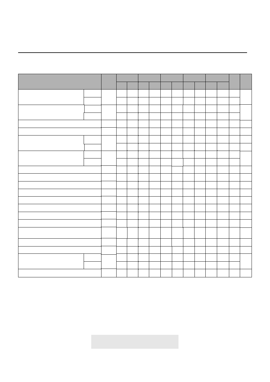
Operating AC Characteristics
( V
DD
= 3.3V +/- 0.3 V, All Operating Range )
Notes
2
5
5
5
5
5
Parameter
Clock cycle time
Access time from CLK
Data-out hold time
Data-out to high impedance time
CLK high level width
CLK low level width
Input setup time
Input hold time
ACTIVE to ACTIVE command period
ACTIVE to PRECHARGE command period
PRECHARGE to ACTIVE command period
ACTIVE to READ/WRITE delay time
ACTIVE(one) to ACTIVE(another) command
READ/WRITE command to READ/WRITE
command
CL = 3
CL = 2
CL = 3
CL = 2
CL = 2
CL = 3
CL = 2
Data-in to PRECHARGE command
Data-out to high impedance from
PRECHARGE command
Data-in to BURST stop command
Refresh time(4,096 cycle)
CL = 3
CL = 2
Data-out to low impedance time
Symbol
t
CK
t
AC
t
CH
t
CL
t
OH
t
HZ
t
LZ
t
IS
t
IH
t
RC
t
RAS
t
RP
t
RCD
t
RRD
t
CCD
t
DPL
t
BDL
t
ROH
t
REF
-6
Min. Max.
2.5
2.5
2.5
5
1
1
1.5
60
42
18
100k
18
12
1
6
5.5
2
1
3
2
64
-7
Min. Max.
3
3
1.5
5.5
1
1
2
63
18
100k
18
14
1
7
2.5
45
5.5
2
1
3
2
64
-8
Min. Max.
3
3
2.5
1.5
6
6
1
1
2
64
46
18
100k
18
16
1
8
10
6
6
2
1
3
2
64
-55
Min. Max.
2.0
2.0
2.0
4.5
1
1
1.5
60
42
18
100k
18
10
1
5.5
4.5
2
1
3
2
64
-10
Min. Max.
3
3
2.5
1.5
6
6
1
1
2
70
50
20
100k
20
18
1
10
10
6
6
2
1
3
2
64
CL = 3
3
4
_
10
_
5.5
_
_
6
6
6
_
_
_
_

Preliminary
19
64Mb SDRAM
Ascend Semiconductor Corporation
Operating AC Characteristics--
Continues
( V
DD
= 3.3V +/- 0.3 V, All Operating Range )
Note :
1. All voltages referenced to Vss.
2. For commercial range parts.
3. For industrial range parts.
4. tHZ defines the time at which the output achieve the open circuit
condition and is not referenced to output voltage levels.
5. These parameters account for the number of clock cycle and
depend on the operating frequency of the clock, as follows :
The number of clock cycles = Specified value of timing/clock period (Count fractions as a whole number)
6.These parameters are for address/command/data/CLK/CKE.
7. Any "≠ " sign on the data means " No guarantee" .
CL = 1
Parameter
Clock cycle time
Access time from CLK
Data-out hold time
Data-out to high impedance time
CLK high level width
CLK low level width
Input setup time
Input hold time
ACTIVE to ACTIVE command period
ACTIVE to PRECHARGE command period
PRECHARGE to ACTIVE command period
ACTIVE to READ/WRITE delay time
ACTIVE(one) to ACTIVE(another) command
READ/WRITE command to READ/WRITE
command
CL = 1
CL = 1
CL = 1
Data-in to PRECHARGE command
Data-out to high impedance from
PRECHARGE command
Data-in to BURST stop command
Refresh time(4,096 cycle)
CL = 1
Data-out to low impedance time
Symbol
t
CK
t
AC
t
CH
t
CL
t
OH
t
HZ
t
LZ
t
IS
t
IH
t
RC
t
RAS
t
RP
t
RCD
t
RRD
t
CCD
t
DPL
t
BDL
t
ROH
t
REF
-15
Min. Max.
3
3
2
6
1
1
2
90
60
22
100k
25
15
1
15
1
1
1
64
12
Units
ns
ns
ns
ns
ns
ns
ns
ns
ns
ns
ns
ns
ns
ns
CLK
CLK
CLK
CLK
ms
Notes
5
5
5
5
5
3
4
6
6

Preliminary
20
64Mb SDRAM
Ascend Semiconductor Corporation
* Ascend reserves the right to change products or specification without notice.
Package Dimension
11.76
+/- 0.20
0.463
+/- 0.008
MAX
0.10
0.004
0.05
0.002
MIN
0.21
+/- 0.05
0.008
+/- 0.002
1.00
+/- 0.10
0.039
+/- 0.004
1.20
0.047
MAX
0.71 0.028
0.35
+0.1 /
-
0.1
0.014
+0.004 /
-
0.004
0.80 0.035
22.62 0.891
MAX
22.22
+/
-
0.10
0.875
+/
-
0.004
0 ≠
8'
0.25 0.010
TYP
10.16
0.400
0.50
0.020
0.45 ~ 0.75
0.018 ~ 0.030
0.125
+0.075 /
-
0.035
0.005
+0.003 /
-
0.001
#1
#27
#54
#28
Dimension in Milimeter/Inchs