 | –≠–ª–µ–∫—Ç—Ä–æ–Ω–Ω—ã–π –∫–æ–º–ø–æ–Ω–µ–Ω—Ç: 10ETF04FP | –°–∫–∞—á–∞—Ç—å:  PDF PDF  ZIP ZIP |
I
F(AV)
Sinusoidal waveform
10
A
V
RRM
200 to 600
V
I
FSM
150
A
V
F
@
10 A, T
J
= 25∞C
1.2
V
t
rr
@ 1A, 100A/µs
50
ns
T
J
- 40 to 150
∞C
Major Ratings and Characteristics
Characteristics
10ETF..FP Units
Description/Features
The 10ETF..FP fast soft recovery QUIET
IR
rectifier series has been optimized for combined
short reverse recovery time and low forward
voltage drop.
The glass passivation ensures stable reliable
operation in the most severe temperature and
power cycling conditions.
Typical applications are both:
output rectification and freewheeling in
inverters, choppers and converters
and input rectifications where severe
restrictions on conducted EMI should be met.
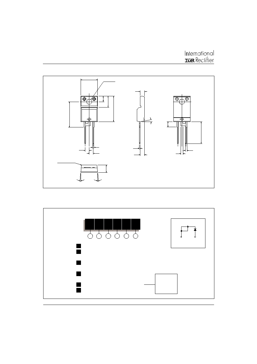
TO-220AC FULLPAK
Package Outline
1
Bulletin I2163 04/02
QUIET
IR
Series
10ETF..FP
V
F
< 1.2V @ 10A
t
rr
= 50ns
V
RRM
200 to 600V
FAST SOFT RECOVERY
RECTIFIER DIODE
www.irf.com
2
10ETF..FP QUIET
IR
Series
Bulletin I2163 04/02
www.irf.com
I
F(AV)
Max. Average Forward Current
10
A
@ T
C
= 98∞ C, 180∞ conduction half sine wave
I
FSM
Max. Peak One Cycle Non-Repetitive
150
10ms Sine pulse, rated V
RRM
applied
Surge Current
160
10ms Sine pulse, no voltage reapplied
I
2
t
Max. I
2
t for fusing
112.5
10ms Sine pulse, rated V
RRM
applied
160
10ms Sine pulse, no voltage reapplied
I
2
t
Max. I
2
t for fusing
1600
A
2
s
t = 0.1 to 10ms, no voltage reapplied
Part Number
V
RRM
, maximum
V
RSM
, maximum non repetitive
I
RRM
peak reverse voltage
peak reverse voltage
150∞C
V
V
mA
10ETF02FP
200
300
2
10ETF04FP
400
500
10ETF06FP
600
700
Voltage Ratings
Absolute Maximum Ratings
Electrical Specifications
Recovery Characteristics
Parameters
10ETF..FP Units
Conditions
A
A
2
s
V
FM
Max. Forward Voltage Drop
1.2
V
@ 10A, T
J
= 25∞C
r
t
Forward slope resistance
23.5
m
T
J
= 150∞C
V
F(TO)
Threshold voltage
0.85
V
I
RM
Max. Reverse Leakage Current
0.1
T
J
= 25 ∞C
3.0
T
J
= 150 ∞C
Parameters
10ETF..FP Units
Conditions
V
R
= rated V
RRM
mA
t
rr
Reverse Recovery Time
145
ns
I
F
@ 10Apk
I
rr
Reverse Recovery Current
2.75
A
@ 25A/ µs
Q
rr
Reverse Recovery Charge
0.32
µC
@ 25∞C
S
Snap Factor
0.6
Parameters
10ETF..FP Units
Conditions
3
10ETF..FP QUIET
IR
Series
Bulletin I2163 04/02
www.irf.com
T
J
Max. Junction Temperature Range
- 40 to 150
∞C
T
stg
Max. Storage Temperature Range
- 40 to 150
∞C
R
thJC
Max. Thermal Resistance Junction
2.5
∞C/W
DC operation
to Case
R
thJA
Max. Thermal Resistance Junction
62
∞C/W
to Ambient
R
thCS
Typical Thermal Resistance, Case to
0.5
∞C/W
Mounting surface , smooth and greased
Heatsink
wt
Approximate Weight
2 (0.07)
g (oz.)
T
Mounting Torque
Min.
6 (5)
Max.
12 (10)
Case Style
TO-220AC FULLPAK
(94/V0)
Thermal-Mechanical Specifications
Parameters
10ETF..FP Units
Conditions
Kg-cm
(Ibf-in)
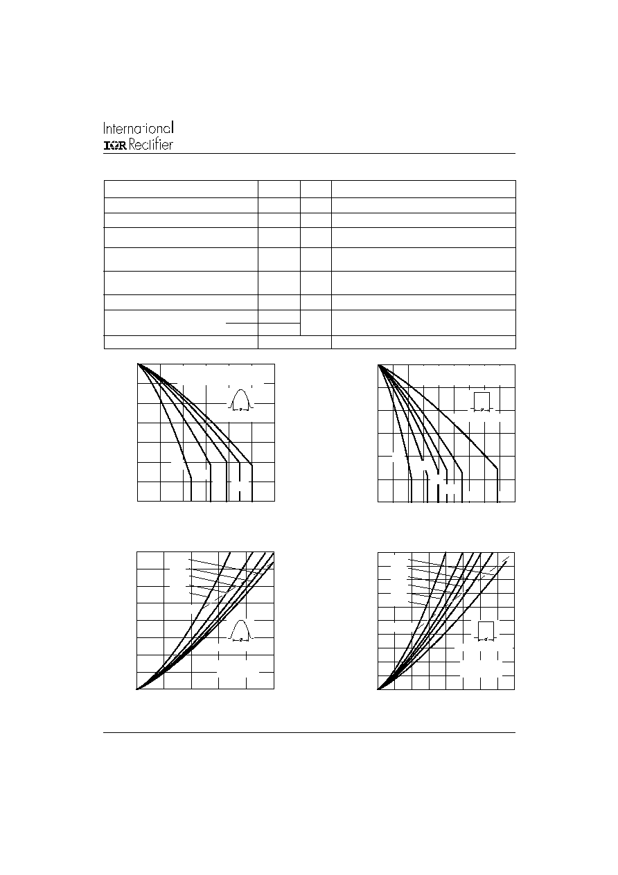
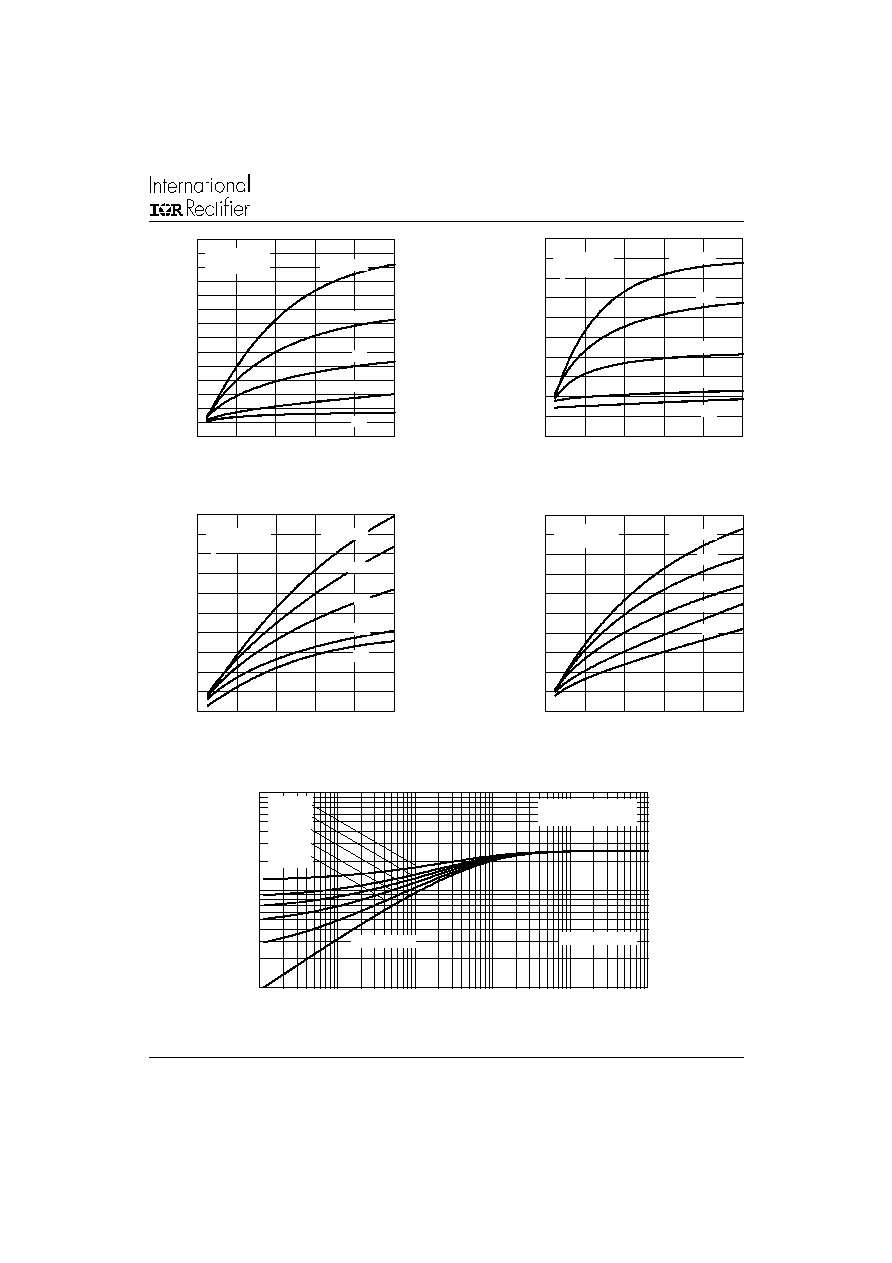
Fig. 1 - Current Rating Characteristics
Fig. 2 - Current Rating Characteristics
Fig. 3 - Forward Power Loss Characteristics
Fig. 4 - Forward Power Loss Characteristics
0
2
4
6
8
1 0
1 2
1 4
1 6
0
2
4
6
8
1 0
A vera g e Forw a rd C urren t (A )
RM S Lim it
Ma
x
i
mu
m A
v
e
r
a
g
e
F
o
r
w
a
r
d
P
o
w
e
r
L
o
s
s
(
W
)
C o nd uction A ng le
18 0
12 0
9 0
6 0
3 0
10E TF.. Se rie s
T = 150 C
J
0
4
8
1 2
1 6
2 0
0
4
8
1 2
1 6
D C
180
120
90
60
30
A ve ra g e Forw a rd C u rre n t (A)
RM S Lim it
Ma
x
i
mu
m A
v
e
r
a
g
e
F
o
r
w
a
r
d
P
o
w
e
r
L
o
s
s
(
W
)
C o nd u c tio n P e rio d
10ETF .. Se rie s
T = 150 C
J
Average Forward Current (A)
Maximum Allowable Case Temperature (∞C)
Average Forward Current (A)
Maximum Allowable Case Temperature (∞C)
80
90
100
110
120
130
140
150
0
2
4
6
8
10
12
30∞
60∞
90∞
120∞
180∞
Conduction Angle
10ETF.. Series
RthJC (DC) = 2.5 ∞C/W
90
100
110
120
130
140
150
0
2
4
6
8
10 12 14 16 18
DC
30∞
60∞
90∞
120∞
180∞
Conduction Period
10ETF.. Series
RthJC (DC) = 2.5 ∞C/W
4
10ETF..FP QUIET
IR
Series
Bulletin I2163 04/02
www.irf.com
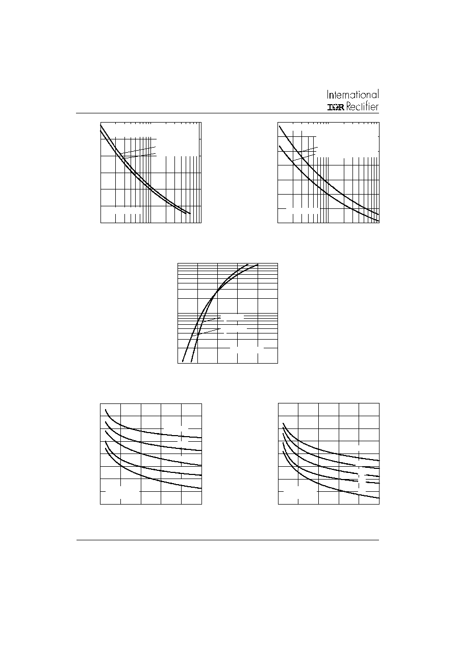
Fig. 8 - Recovery Time Characteristics, T
J
= 25∞C
Fig. 9 - Recovery Time Characteristics, T
J
= 150∞C
Fig. 7 - Forward Voltage Drop Characteristics
Fig. 5 - Maximum Non-Repetitive Surge Current
Fig. 6 - Maximum Non-Repetitive Surge Current
4 0
6 0
8 0
1 0 0
1 2 0
1 4 0
1 6 0
1
1 0
1 0 0
P
e
ak
Ha
l
f
S
i
n
e
W
a
v
e
F
o
r
w
ar
d C
u
r
r
e
n
t
(
A
)
N u mber O f Equa l Am plitu de H alf Cycle C u rren t Pu lses (N)
Initia l T = 150 C
@ 60 Hz 0.00 83 s
@ 50 Hz 0.01 00 s
J
At An y Ra ted Lo a d C o n d itio n A nd W ith
R a ted V A p p lie d Fo llo w in g Surg e .
R R M
1 0ET F.. Se ries
40
60
80
1 00
1 20
1 40
1 60
1 80
0 .0 1
0 .1
1
P
e
ak
H
a
l
f
S
i
n
e
W
a
v
e
F
o
r
w
ar
d
C
u
r
r
e
n
t
(
A
)
Pu lse Train Du ration (s)
Initia l T = 150 C
N o Vo lta ge Rea p p lied
Ra te d V Re app lied
R R M
Versu s Pulse Tra in D ura tio n.
M axim um N on Rep e titive S urg e C urrent
J
10ET F.. Se ries
1
1 0
10 0
0.5
1
1 .5
2
2.5
3
T = 25 C
J
I
n
s
t
a
n
t
a
ne
o
u
s
F
o
r
w
a
r
d
C
u
r
r
e
nt
(
A
)
In stan tan e ous Forw a rd V olta g e (V )
T = 150 C
J
10ET F.. Se ries
0
0 .05
0 .1
0 .15
0 .2
0
4 0
8 0
1 2 0
16 0
2 0 0
10 A
M
a
x
i
mu
m R
e
v
e
r
s
e
R
e
c
o
v
e
r
y
T
i
me
-
T
r
r
(
s
)
Rate O f Fall O f Fo rw a rd C urre n t - d i/d t (A / s)
5 A
1 A
I = 20 A
FM
2 A
10ETF.. Se ries
T = 25 C
J
0
0 .1
0 .2
0 .3
0 .4
0
4 0
80
12 0
1 6 0
2 0 0
10 A
M
a
x
i
mu
m R
e
v
e
r
s
e
R
e
c
o
v
e
r
y
T
i
me
-
T
r
r
(
s
)
Rate O f Fa ll O f Forw a rd C urre n t - d i/dt (A / s)
5 A
1 A
I = 20 A
FM
2 A
10ETF.. Se ries
T = 150 C
J
5
10ETF..FP QUIET
IR
Series
Bulletin I2163 04/02
www.irf.com
Fig. 14 - Thermal Impedance Z
thJC
Characteristics
Fig. 12 - Recovery Current Characteristics, T
J
= 25∞C
Fig. 13 - Recovery Current Characteristics, T
J
= 150∞C
Fig. 10 - Recovery Charge Characteristics, T
J
= 25∞C
Fig. 11 - Recovery Charge Characteristics, T
J
= 150∞C
0
0.2
0.4
0.6
0.8
1
1.2
1.4
0
4 0
8 0
1 2 0
1 6 0
20 0
10 A
Rate O f Fall O f Forw a rd C urre n t - di/dt (A / s)
5 A
1 A
M
a
x
i
m
u
m
R
e
v
e
rs
e
R
e
c
o
ve
ry C
h
a
r
g
e
-
Qr
r (
C
)
I = 20 A
FM
2 A
10ET F.. Se ries
T = 25 C
J
0
0 .5
1
1 .5
2
2 .5
0
4 0
8 0
1 2 0
1 6 0
20 0
10 A
Rate O f Fall O f Forw a rd C urre n t - di/dt (A/ s)
5 A
1 A
M
a
x
i
mu
m R
e
v
e
r
s
e
R
e
c
o
v
e
r
y
C
h
a
r
g
e
-
Q
r
r
(
C
)
I = 20 A
FM
2 A
10ETF.. Se rie s
T = 150 C
J
0
3
6
9
12
15
0
4 0
8 0
12 0
160
200
Ra te O f Fall O f Forw a rd C urren t - d i/dt (A / s)
M
a
x
i
m
u
m
R
e
v
e
r
s
e
R
e
c
o
v
e
r
y
C
u
rre
n
t
-
I
rr (
A
)
I = 20 A
FM
2 A
1 0 A
5 A
1 A
1 0E T F.. Se ries
T = 25 C
J
0
4
8
1 2
1 6
2 0
0
4 0
80
1 20
1 60
20 0
Ra te O f Fa ll O f Forw ard C urre n t - d i/d t (A / s)
M
a
xi
m
u
m
Re
v
e
r
s
e Rec
o
v
e
r
y
C
u
r
r
en
t
-
I
r
r
(
A
)
I = 20 A
F M
10 A
1 A
5 A
2 A
1 0 ETF.. Se ries
T = 1 5 0 C
J
Square Wave Pulse Duration (s)
Transient Thermal Impedance Z
thJC
(∞C/W)
0.1
1
10
0.0001
0.001
0.01
0.1
1
10
D = 0.50
D = 0.33
D = 0.25
D = 0.17
D = 0.08
Steady State Value
(DC Operation)
Single Pulse
10ETF.. Series
6
10ETF..FP QUIET
IR
Series
Bulletin I2163 04/02
www.irf.com
5∞± 0.5∞
3.1
3.3
13.5
13.7
R0.5
R0.7 (2 PLACES)
3.1
HOLE ¯ 3.4
10.4
0.7
4.6
TYP.
5∞± 0.5∞
4.8
0.9
2.54 TYP.
2.54
10.6
16.4
16.0
3.7
7.1
0.48
2.85
2.8
1.4
1.15
15.4
3.2
6.7
15.8
1.05
1.3
0.44
2.65
2.6
TYP
10∞
Outline Table
Dimensions in millimeters and inches
Ordering Information Table
10
E
T
F
06 FP
Device Code
1
5
2
4
3
1
-
Current Rating
2
-
Circuit Configuration:
E = Single Diode
3
-
Package:
T = TO-220AC
4
-
Type of Silicon:
F = Fast Soft Recovery Rectifier
5
-
Voltage code: Code x 100 = V
RRM
6
-
TO-220 FULLPAK
02 = 200V
04 = 400V
06 = 600V
6
1
CATHODE
ANODE
3
2
7
10ETF..FP QUIET
IR
Series
Bulletin I2163 04/02
www.irf.com
IR WORLD HEADQUARTERS: 233 Kansas St., El Segundo, California 90245, USA Tel: (310) 252-7105
TAC Fax: (310) 252-7309
Visit us at www.irf.com for sales contact information. 04/02
Data and specifications subject to change without notice.
This product has been designed and qualified for Industrial Level.
Qualification Standards can be found on IR's Web site.