1
130HF(R) SERIES
Stud Version
STANDARD RECOVERY DIODES
130 A
Bulletin I2019 rev. A 07/94
www.irf.com
Features
High current carrying capability
High surge current capability
Types up to 1200V V
RRM
Stud cathode and stud anode version
Standard JEDEC types
Diffused junction
Typical Applications
Battery chargers
Converters
Power supplies
Machine tool controls
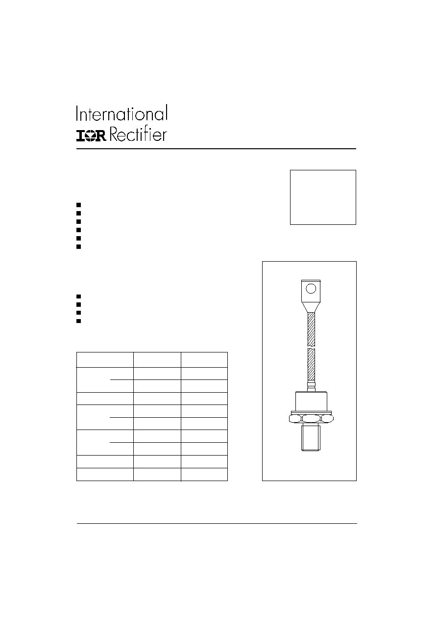
case style
DO-205AC (DO-30)
I
F(AV)
130
A
@ T
C
125
∞C
I
F(RMS)
200
A
I
FSM
@
50Hz
2000
A
@ 60Hz
2100
A
I
2
t
@
50Hz
20
KA
2
s
@ 60Hz
18
KA
2
s
V
RRM
range
400 to 1200
V
T
J
-40 to 180
∞C
Parameters
130HF(R)
Units
Major Ratings and Characteristics
130HF(R) Series
2
Bulletin I2019 rev. A 07/94
www.irf.com
Voltage
V
RRM
, maximum repetitive
V
RSM
, maximum non-
I
RRM
max.
Type number
Code
peak reverse voltage
repetitive peak rev. voltage
@ 180∞C
V
V
mA
40
400
500
130HF(R)
80
800
900
15
120
1200
1300
I
F(AV)
Max. average forward current
130
A
180∞ conduction, half sine wave
@ Case temperature
125
∞C
I
F(RMS)
Max. RMS forward current
200
A
DC @ 115∞C case temperature
I
FSM
Max. peak, one-cycle forward,
2000
t = 10ms
No voltage
non-repetitive surge current
2100
t = 8.3ms
reapplied
1680
t = 10ms
100% V
RRM
1760
t = 8.3ms
reapplied
Sinusoidal half wave,
I
2
t
Maximum I
2
t for fusing
20
t = 10ms
No voltage
Initial T
J
= T
J
max
18
t = 8.3ms
reapplied
14
t = 10ms
100% V
RRM
13
t = 8.3ms
reapplied
I
2
t
Maximum I
2
t for fusing
200
KA
2
s
t = 0.1 to 10ms, no voltage reapplied
V
F(TO)1
Low level value of threshold
voltage
V
F(TO)2
High level value of threshold
voltage
r
f1
Low level value of forward
slope resistance
r
f2
High level value of forward
slope resistance
V
FM
Max. forward voltage drop
1.5
V
I
pk
=
500A
, T
J
= 25 ∞C
Parameter
130HF(R)
Units Conditions
Forward Conduction
0.76
(16.7% x
x I
F(AV)
< I <
x I
F(AV)
), T
J
= T
J
max.
0.95
(I >
x I
F(AV)
), T
J
= T
J
max.
1.41
(16.7% x
x I
F(AV)
< I <
x I
F(AV)
), T
J
= T
J
max.
1.02
(I >
x I
F(AV)
), T
J
= T
J
max.
KA
2
s
A
V
m
ELECTRICAL SPECIFICATIONS
Voltage Ratings
130HF(R) Series
Bulletin I2019 rev. A 07/94
www.irf.com
3
Parameter
130HF(R)
Units
Conditions
∞C
T
J
Max. operating temperature range
-40 to 180
T
stg
Max. storage temperature range
-55 to 180
R
thJC
Max. thermal resistance, junction to case
0.3
DC operation
R
thCS
Max. thermal resistance, case to heatsink
0.08
Mounting surface, smooth, flat and greased
T
Max. allowed mounting torque +0 -20%
11
Not lubricated threads
10
Lubricated threads
wt
Approximate weight
120
g
Case style
DO-205AC(DO-30)
See Outline Table
K/W
Nm
Thermal and Mechanical Specification
R
thJC
Conduction
(The following table shows the increment of thermal resistence R
thJC
when devices operate at different conduction angles than DC)
180∞
0.052
0.042
T
J
= T
J
max.
120∞
0.064
0.070
90∞
0.083
0.090
K/W
60∞
0.117
0.120
30∞
0.177
0.180
Conduction angle
Sinusoidal conduction
Rectangular conduction Units
Conditions
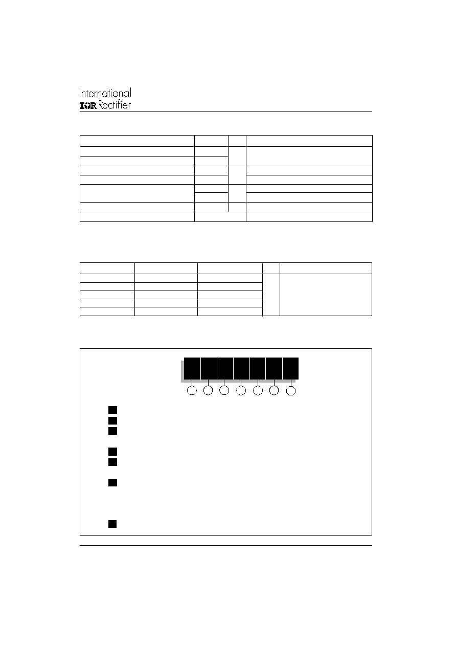
Ordering Information Table
130 HF
R
120
P
B
V
1
2
3
4
5
6
Device Code
1
-
Essential Part Number
2
-
Diode
3
-
None = Stud Normal Polarity (Cathode to Stud)
R = Stud Reverse Polarity (Anode to Stud)
4
-
Voltage code: Code x 10 = V
RRM
(See Voltage Ratings table)
5
-
P = Stud base DO-205AC(DO-30) 1/2" 20UNF-2A
M= Stud base DO-205AC(DO-30) M12x1.75
6
-
B = Flag top terminals (for Cathode/ Anode Leads)
S = Isolated lead with silicone sleeve
(Red = Reverse Polarity; Blue = Normal Polarity)
None = Not isolated lead
7
-
V = Glass-metal seal
7

130HF(R) Series
4
Bulletin I2019 rev. A 07/94
www.irf.com
Outline Table
DO-205AC (DO-30) Flag
All dimensions in millimeters (inches)
GLASS-METAL SEAL
MAX.
21
(
0
.
8
2)
M
AX.
16.5 (0.65)
6.
5 (
0
.26)
MI
N
.
DIA. 8.5 (0.33) NOM.
157
(
6
.
1
8
)
55 (
2
.
1
6)
MIN
.
DIA. 23.5 (0.93) MAX.
24 (
0
.94)
MA
X
.
SW 27
* FOR METRIC DEVICE: M12 X 1.75
17
0 (
6
.69)
1/2"-20UNF-2A*
1
2
.
5
(
0
.4
9
)
M
AX.
C.S. 16mm
2.6 (0.10) MAX.
2
35 (
1
.38)
M
AX.
(0.015 s.i.)
M
AX.
GLASS-METAL SEAL
MA
X
.
21 (
0
.
8
2)
M
AX.
DIA. 23.5 (0.93) MAX.
24
(
0
.
9
4
)
12.
5 (
0
.
4
9)
16.5 (0.65)
5.6 (0.22)
DIA. 5.54 (0.22)
2.
4 (
0
.
09)
27
(
1
.
06)
41
(
1
.
61)
M
A
X
.
9.
5 (
0
.
3
7
)
*FOR METRIC DEVICE. M12 X 1.75
36.
5 (
1
.
4
4
)
1/2"-20UNF-2A*
Conforms to JEDEC DO-205AC (DO-30)
All dimensions in millimeters (inches)
130HF(R) Series
Bulletin I2019 rev. A 07/94
www.irf.com
5
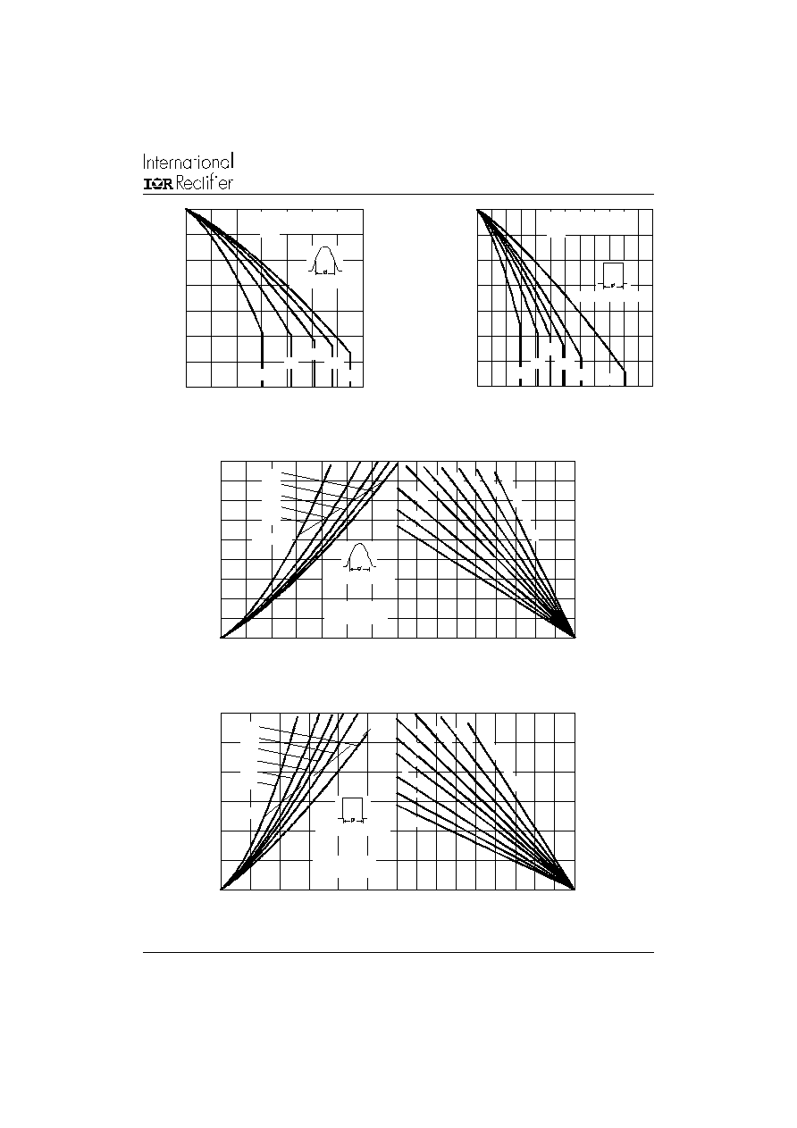
Fig. 1 - Current Ratings Characteristics
Fig. 2 - Current Ratings Characteristics
110
120
130
140
150
160
170
180
0
20
40
60
80
100
120
140
30∞
60∞
90∞
120∞
180∞
Average Forward Current (A)
Conduction Angle
130HF(R) Series
R (DC) = 0.3 K/W
M
a
x
i
m
u
m
A
l
l
o
wabl
e
C
a
s
e
T
e
m
p
e
r
at
ur
e
(
∞C
)
thJC
110
120
130
140
150
160
170
180
0
40
80
120
160
200
240
DC
30∞
60∞
90∞
120∞
180∞
Conduction Period
130HF(R) Series
R (DC) = 0.3 K/W
thJC
M
a
x
i
m
u
m
A
l
low
a
b
l
e C
a
s
e
Te
m
p
er
a
t
u
r
e (
∞C
)
Average Forward Current (A)
Fig. 3 - Forward Power Loss Characteristics
0
20
40
60
80 100 120 140 160 180
Maximum Allowable Ambient Temperature (∞C)
R
=
0
.1
K
/W
-
D
e
l
ta
R
th
SA
0.
2 K
/W
0.3
K
/W
0.4
K
/W
0.5
K
/W
0.6
K/
W
0.8
K
/W
1 K
/W
1 .2
K/W
0
20
40
60
80
100
120
140
160
180
0
20
40
60
80
100
120
140
180∞
120∞
90∞
60∞
30∞
RMS Limit
Conduction Angle
M
a
x
i
m
u
m
A
v
e
r
ag
e
F
o
r
w
ar
d P
o
we
r
Lo
ss (
W
)
Average Forward Current (A)
130HF(R) Series
T = 180∞C
J
Fig. 4 - Forward Power Loss Characteristics
0
20
40
60
80 100 120 140 160 180
Maximum Allowable Ambient Temperature (∞C)
R
=
0
.1
K
/W
-
D
e lt
a
R
th
SA
0.2
K
/W
0.3
K
/W
0.4
K
/W
0.6
K
/W
0 .8
K/
W
1 K/
W
1.2 K
/ W
0.5
K/W
0
40
80
120
160
200
240
0
40
80
120
160
200
240
DC
180∞
120∞
90∞
60∞
30∞
RMS Limit
Conduction Period
M
a
x
i
m
u
m
A
v
er
a
g
e F
o
r
w
a
r
d
P
o
w
e
r
L
o
s
s
(
W
)
Average Forward Current (A)
130HF(R) Series
T = 180∞C
J