Major Ratings and Characteristics
Parameters 130MT.KB 160MT.KB Units
I
O
130 (160)
160 (200)
A
@ T
C
85 (62)
85 (60)
∞C
I
FSM
@ 50Hz
1130
1430
A
@ 60Hz
1180
1500
A
I
2
t
@ 50Hz
6400
10200
A
2
s
@ 60Hz
5800
9300
A
2
s
I
2
t
64000
102000
A
2
s
V
RRM
range
800 to 1600
V
T
STG
range
- 40 to 150
∞C
T
J
range
- 40 to 150
∞C
Features
Package fully compatible with the industry standard INT-A-
pak power modules series
High thermal conductivity package, electrically insulated case
Outstanding number of power encapsulated components
Excellent power volume ratio, outline for easy connections to
power transistor and IGBT modules
4000 V
RMS
isolating voltage
UL E78996 approved
Description
A range of extremely compact, encapsulated three phase
bridge rectifiers offering efficient and reliable operation.
They are intended for use in general purpose and heavy
duty applications.
www.irf.com
130 A
160 A
THREE PHASE BRIDGE
Bulletin I27502 rev. A 05/03
1
MT..KB SERIES
Power Modules
130-160MT..KB Series
Bulletin I27502 rev. A 05/03
www.irf.com
2
ELECTRICAL SPECIFICATIONS
Voltage Ratings
Voltage
V
RRM
, maximum repetitive
V
RSM
, maximum non-
I
RRM
max.
Type number
Code
peak reverse voltage
repetitive peak rev. voltage
@ T
J
max.
V
V
mA
80
800
900
100
1000
1100
130-160MT..KB 120 1200 1300 10
140
1400
1500
160
1600
1700
I
O
Maximum DC output current
130 (160)
160 (200)
A
120∞ Rect conduction angle
@ Case temperature
85 (62)
85 (60)
∞C
I
FSM
Maximum peak, one-cycle forward,
1130
1430
A
t = 10ms
No voltage
non-repetitive surge current
1180
1500
t = 8.3ms
reapplied
950
1200
t = 10ms
100% V
RRM
1000
1260
t = 8.3ms
reapplied
Initial T
J
= T
J
max.
I
2
t
Maximum I
2
t for fusing
64000
10200
A
2
s
t = 10ms
No voltage
5800
9300
t = 8.3ms
reapplied
4500
7200
t = 10ms
100% V
RRM
4100
6600
t = 8.3ms
reapplied
I
2
t
Maximum I
2
t for fusing
64000
102000
A
2
s
t = 0.1 to 10ms, no voltage reapplied
V
F(TO)1
Low level value of threshold voltage
0.78
0.81
V
(16.7% x
x I
F(AV)
< I <
x I
F(AV)
), @ T
J
max.
V
F(TO)2
High level value of threshold voltage
0.99
1.04
(I >
x I
F(AV)
), @ T
J
max.
r
f1
Low level value of forward slope resistance
4.59
3.52
m
(16.7% x
x I
F(AV)
< I <
x I
F(AV)
), @ T
J
max.
r
f2
High level value of forward slope resistance
4.17
3.13
(I >
x I
F(AV)
), @ T
J
max.
V
FM
Maximum forward voltage drop
1.63
1.49
V
I
pk
= 200A, T
J
= 25∞C, t
p
= 400µs single junction
V
INS
RMS isolation voltage
4000
4000
V
T
J
= 25∞C, all terminal shorted
f = 50Hz, t = 1s
Parameter 130MT.KB 160MT.KB Units Conditions
Forward Conduction
Thermal and Mechanical Specifications
T
J
Max. junction operating temperature range
-40 to 150
∞C
T
stg
Max. storage temperature range
-40 to 150
∞C
R
thJC
Max. thermal resistance, junction to case
0.16
0.12
K/W
DC operation per module
0.93
0.73
DC operation per junction
0.18
0.15
120∞ Rect condunction angle per module
1.08
0.88
120∞ Rect condunction angle per junction
R
thCS
Max. thermal resistance, case to heatsink
0.03
K/W
Per module
Mounting surface smooth, flat and greased
T
Mounting torque ± 10%
to heatsink
4 to 6
Nm
to terminal
3 to 4
wt
Approximate weight
176
g
Parameter 130MT.KB 160MT.KB Units Conditions
A mounting compound is recommended and the
torque should be rechecked after a period of 3
hours to allow for the spread of the compound.
Lubricated threads.
130-160MT..KB Series
Bulletin I27502 rev. A 05/03
www.irf.com
3
16 0 MT 160 K B
1
2
3
1
-
Current rating code: 13 = 130 A (Avg)
16 = 160 A (Avg)
2
-
Three phase diodes bridge
3
-
Essential part number
4
-
Voltage code: Code x 10 = V
RRM
(See Voltage Ratings Table)
5
- Generation
II
4
Device Code
Ordering Information Table
5
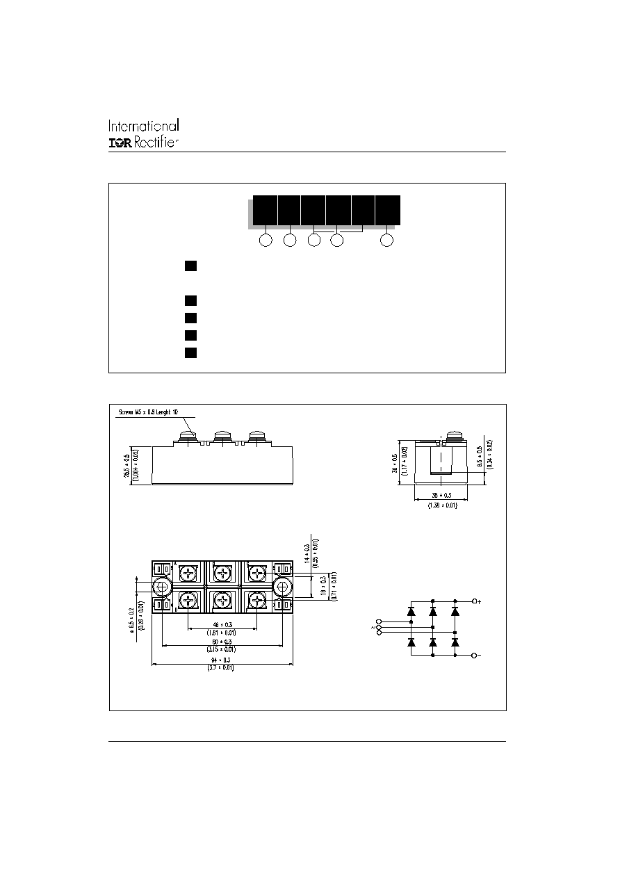
Outline Table (without optional barriers)
All dimensions in millimeters (inches)
A
B
C
D
E
F
NOTE: To order the Optional Hardware see Bulletin I27900
130-160MT..KB Series
Bulletin I27502 rev. A 05/03
www.irf.com
4
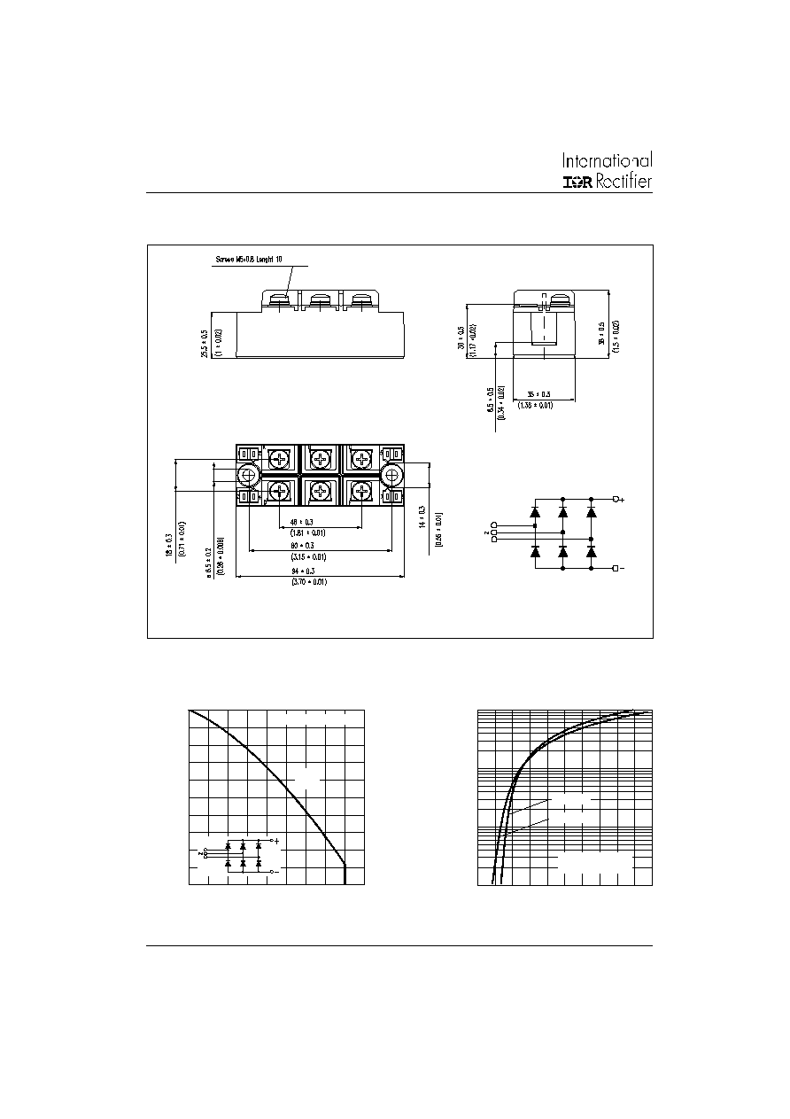
Outline Table (with optional barriers)
All dimensions in millimeters (inches)
A
B
C
D
E
F
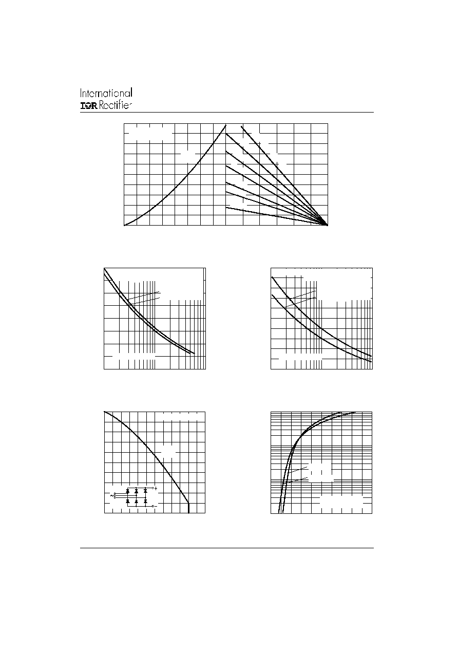
Fig. 2 - Forward Voltage Drop Characteristics
Fig. 1 - Current Ratings Characteristics
50
60
70
80
90
100
110
120
130
140
150
0
20
40
60
80 100 120 140 160 180
Ma
x
i
m
u
m
A
l
l
o
w
a
bl
e
C
ase
T
e
m
per
a
t
u
r
e
(
∞
C)
Total Output Current (A)
120∞
(Rect)
130MT..KB Series
1
10
100
1000
0
1
2
3
4
5
T = 25∞C
J
I
n
st
an
t
a
n
eou
s
F
o
r
wa
r
d
C
u
r
r
e
n
t
(
A)
Instantaneous Forward Voltage (V)
130MT..KB Series
Per Junction
T = 150∞C
J
130-160MT..KB Series
Bulletin I27502 rev. A 05/03
www.irf.com
5
Fig. 7 - Forward Voltage Drop Characteristics
Fig. 6 - Current Ratings Characteristics
1
10
100
1000
0
1
2
3
4
5
T = 25∞C
J
In
s
t
an
tan
e
o
u
s
F
o
r
w
a
r
d
C
u
rr
e
n
t
(
A
)
Instantaneous Forward Voltage (V)
160MT..KB Series
Per Junction
T = 150∞C
J
50
60
70
80
90
100
110
120
130
140
150
0
40
80
120
160
200
240
M
a
x
i
m
u
m
A
l
l
o
wa
bl
e
C
as
e
T
em
per
a
t
u
r
e
(
∞
C)
Total Output Current (A)
120∞
(Rect)
160MT..KB Series
Fig. 3 - Total Power Loss Characteristics
Fig. 4 - Maximum Non-Repetitive Surge Current
Fig. 5 - Maximum Non-Repetitive Surge Current
0
25
50
75
100
125
150
Maximum Allowable Ambient Temperature (∞C)
R
=
0.0
5
K
/W
-
D
elt
a
R
th
S
A
0.1
2
K/W
0.2
K/W
0.3
K/W
0.5
K/W
0.7 K
/W
1.5 K/W
0
50
100
150
200
250
300
350
400
450
500
0
20
40
60
80
100 120 140 160
Total Output Current (A)
Ma
x
i
m
u
m
T
ot
a
l
P
o
w
e
r
L
os
s
(
W
)
120∞
(Rect)
130MT..KB Series
T = 150∞C
J
200
300
400
500
600
700
800
900
1000
1
10
100
Pea
k
H
a
l
f
Si
n
e
W
a
v
e
F
o
r
w
a
r
d
C
u
r
r
e
n
t
(
A
)
Number Of Equal Amplitude Half Cycle Current Pulses (N)
Initial T = 150∞C
@ 60 Hz 0.0083 s
@ 50 Hz 0.0100 s
At Any Rated Load Condition And With
Rated V
Applied Following Surge.
RRM
J
130MT..KB Series
200
300
400
500
600
700
800
900
1000
1100
1200
0.01
0.1
1
P
e
a
k
H
a
lf
S
i
n
e
W
a
v
e
F
o
rw
a
r
d
C
u
rre
n
t
(A
)
Pulse Train Duration (s)
Maximum Non Repetitive Surge Current
130MT..KB Series
Initial T = 150∞C
No Voltage Reapplied
Rated V
Reapplied
RRM
Versus Pulse Train Duration.
J