 | –≠–ª–µ–∫—Ç—Ä–æ–Ω–Ω—ã–π –∫–æ–º–ø–æ–Ω–µ–Ω—Ç: 25F25 | –°–∫–∞—á–∞—Ç—å:  PDF PDF  ZIP ZIP |
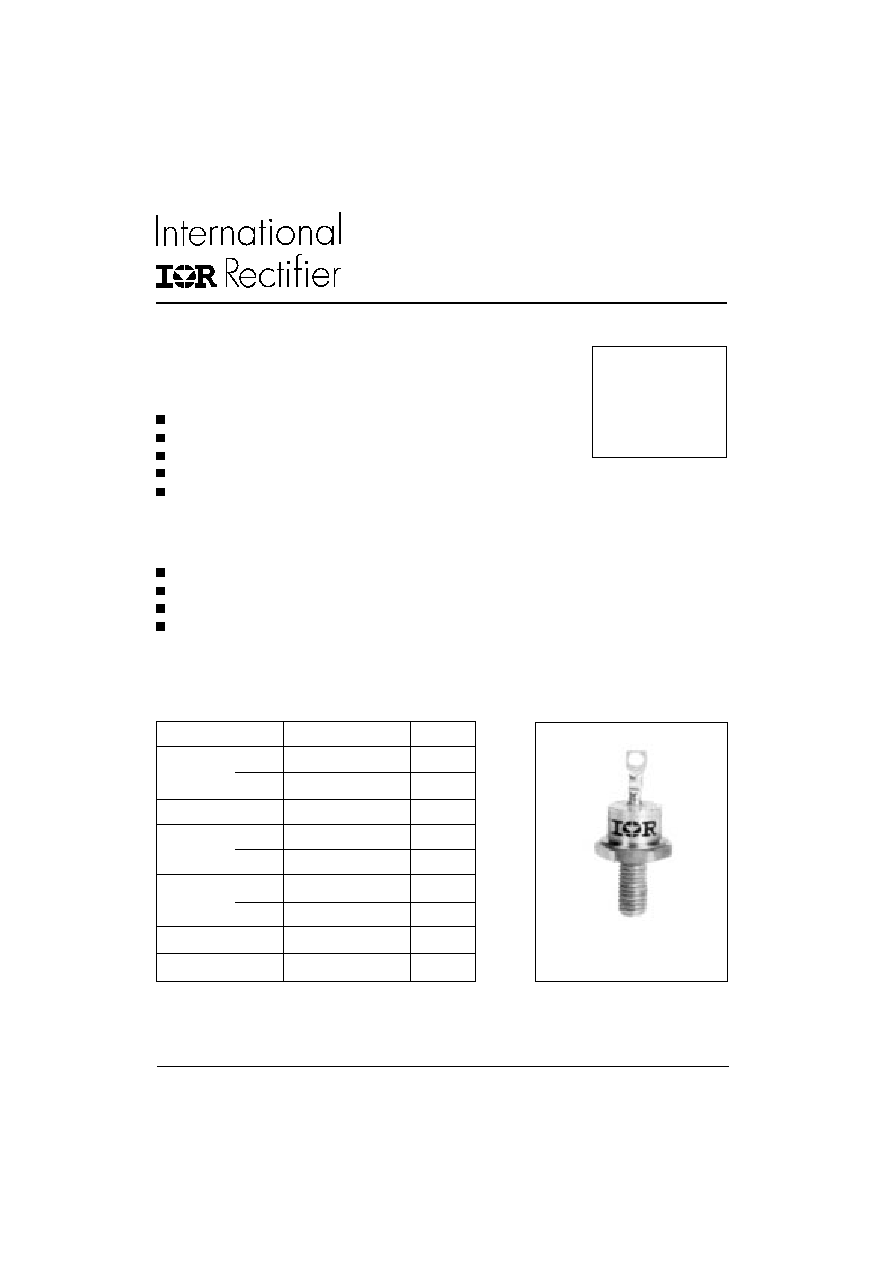
25F(R) SERIES
STANDARD RECOVERY DIODES
25 A
1
Stud Version
Bulletin I2018 rev. B 09/98
www.irf.com
Features
High surge current capability
Avalanche types available
Stud cathode and stud anode version
Wide current range
Types up to 1200V V
RRM
Typical Applications
Battery charges
Converters
Power supplies
Machine tool controls
Parameters
25F(R)
Units
I
F(AV)
25
A
@ T
C
120
∞C
I
F(RMS)
40
A
I
FSM
@
50Hz
356
A
@ 60Hz
373
A
I
2
t
@
50Hz
636
A
2
s
@ 60Hz
580
A
2
s
V
RRM
range
100 to 1200
V
T
J
range
- 65 to 175
∞C
Major Ratings and Characteristics
case style
DO-203AA (DO-4)
25F(R) Series
2
Bulletin I2018 rev. B 09/98
www.irf.com
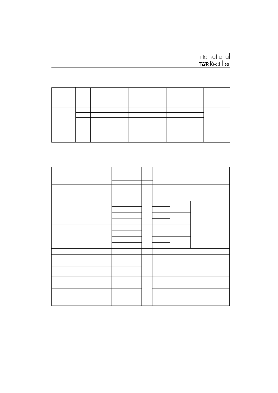
Voltage
V
RRM
, maximum
V
RSM
, maximum non-
V
R(BR)
, minimum
I
RRM
max.
Type number
Code
repetitive peak
repetitive peak
avalanche
@ T
J
= 175∞C
reverse voltage
reverse voltage
voltage
V
V
V
(1)
mA
10
100
150
--
20
200
275
--
40
400
500
500
25F(R)
60
600
725
750
12
80
800
950
950
100
1000
1200
1150
120
1200
1400
1350
ELECTRICAL SPECIFICATIONS
Voltage Ratings
I
F(AV)
Max. average forward current
25
A
180∞ conduction, half sine wave
@ Case temperature
120
∞C
I
F(RMS)
Max. RMS forward current
40
A
P
R
Maximum non-repetitive
10
K/W
10µs square pulse, T
J
= T
J
max.
peak reverse power
see note (2)
I
FSM
Max. peak, one-cycle forward,
356
t = 10ms
No voltage
non-repetitive surge current
373
t = 8.3ms
reapplied
300
t = 10ms
100% V
RRM
314
t = 8.3ms
reapplied
Sinusoidal half wave,
I
2
t
Maximum I
2
t for fusing
636
t = 10ms
No voltage
Initial T
J
= T
J
max.
580
t = 8.3ms
reapplied
450
t = 10ms
100% V
RRM
410
t = 8.3ms
reapplied
I
2
t
Maximum I
2
t for fusing
6360
A
2
s
t = 0.1 to 10ms, no voltage reapplied
V
F(TO)1
Low level value of threshold
voltage
V
F(TO)2
High level value of threshold
voltage
r
f
1
Low level value of forward
slope resistance
r
f
2
High level value of forward
slope resistance
V
FM
Max. forward voltage drop
1.30
V
I
pk
= 78A, T
J
= 25∞C, t
p
= 400µs rectangular wave
Parameter
25F(R)
Units Conditions
5.70
(I >
x I
F(AV)
), T
J
= T
J
max.
6.80
(16.7% x
x I
F(AV)
< I <
x I
F(AV)
), T
J
= T
J
max.
m
0.90
(I >
x I
F(AV)
), T
J
= T
J
max.
0.80
(16.7% x
x I
F(AV)
< I <
x I
F(AV)
), T
J
= T
J
max.
V
A
2
s
A
Forward Conduction
(2) Available only for Avalanche version, all other parameters the same as 25F.
(1) Avalanche version only available from V
RRM
400V to 1200V.
25F(R) Series
3
Bulletin I2018 rev. B 09/98
www.irf.com
Parameter
25F(R)
Units
Conditions
T
J
Max. junction operating temperature range
-65 to 175
T
stg
Max. storage temperature range
-65 to 200
R
thJC
Max. thermal resistance, junction to case
1.5
DC operation
R
thCS
Max. thermal resistance, case
Mounting surface, smooth, flat and
to heatsink
greased
T
Mounting torque, ± 10%
1.2
Nm
Lubricated threads
(1.5)
(Not lubricated threads)
wt
Approximate weight
7 (0.25)
g (oz)
Case style
DO-203AA (DO-4)
See Outline Table
∞C
0.5
K/W
Thermal and Mechanical Specifications
180∞
0.28
0.24
T
J
= T
J
max.
120∞
0.39
0.41
90∞
0.50
0.54
60∞
0.73
0.75
30∞
1.20
1.21
Conduction angle
Sinusoidal conduction
Rectangular conduction Units
Conditions
K/W
R
thJC
Conduction
(The following table shows the increment of thermal resistence R
thJC
when devices operate at different conduction angles than DC)
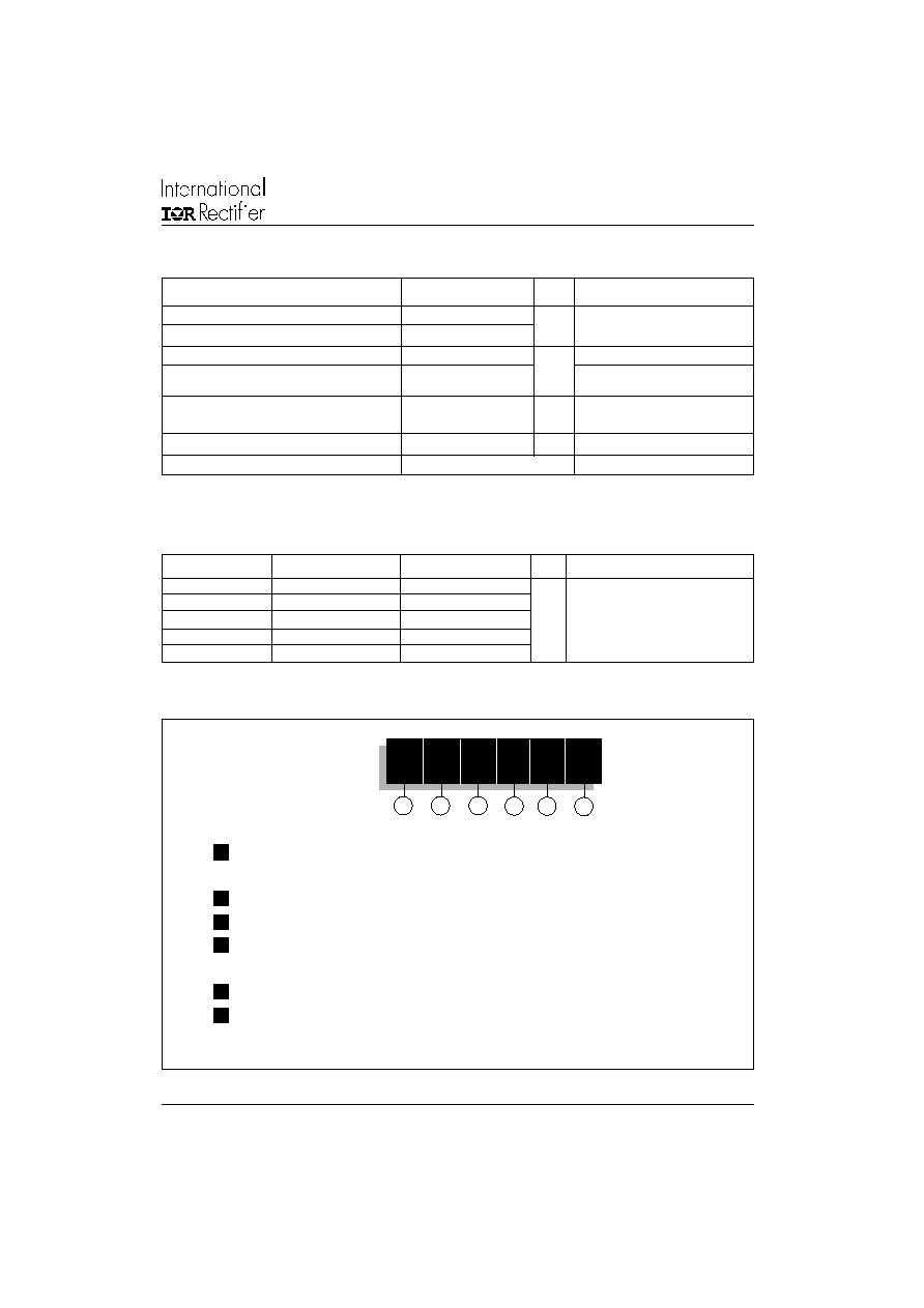
Ordering Information Table
1
2
3
4
5
Device Code
A
25
F
R
120
M
1
-
A
= Avalanche diode
None = Standard diode
2
-
Current rating: Code = I
F(AV)
3
-
F
= Standard device
4
-
None = Stud Normal Polarity (Cathode to Stud)
R
= Stud Reverse Polarity (Anode to Stud)
5
-
Voltage code: Code x 10 = V
RRM
(See Voltage Ratings table)
6
-
None = Stud base DO-203AA (DO-4) 10-32UNF-2A
M
= Stud base DO-203AA (DO-4) M5 X 0.8 - (Not available for Avalanche diodes)
6
25F(R) Series
4
Bulletin I2018 rev. B 09/98
www.irf.com
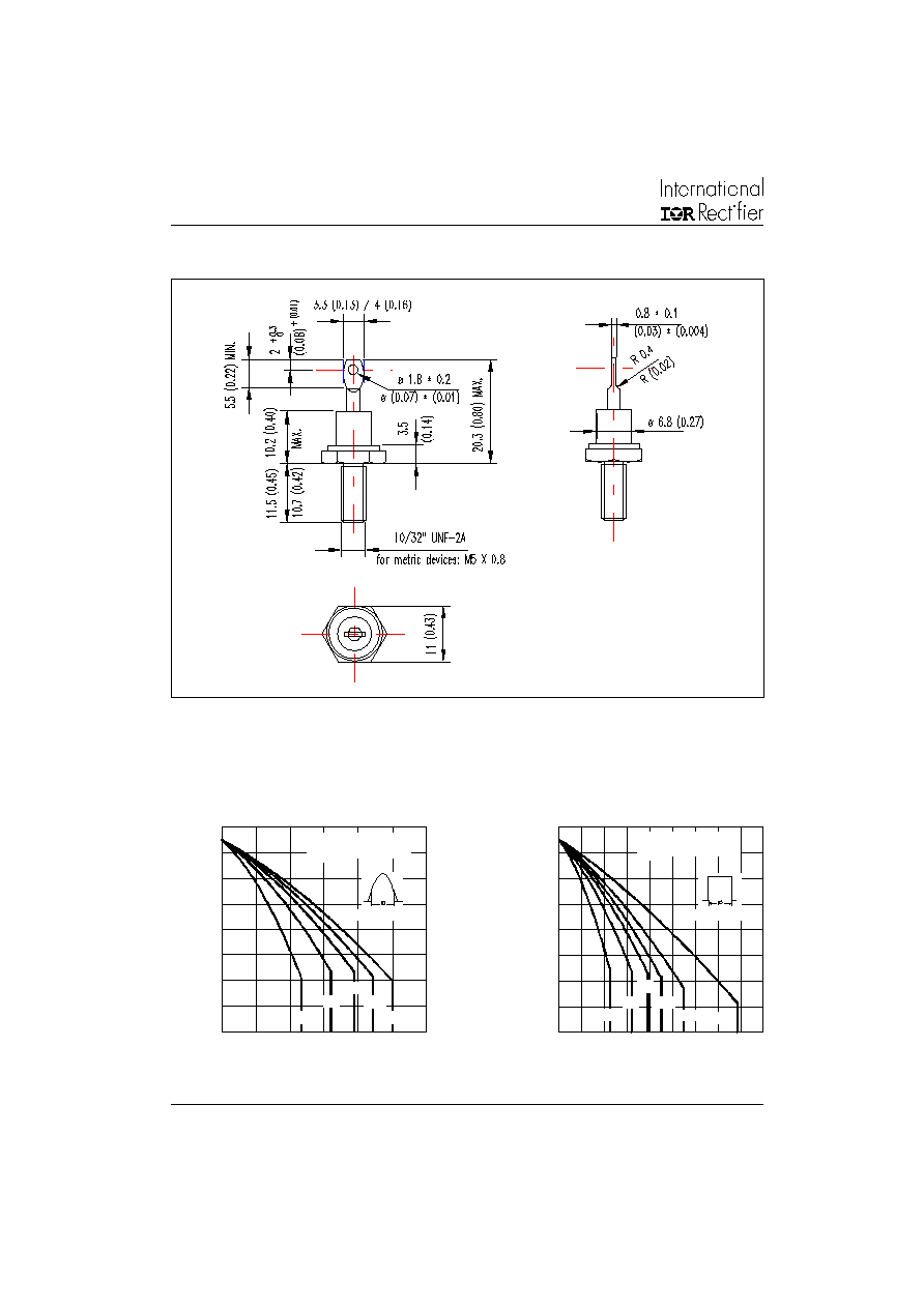
Outlines Table
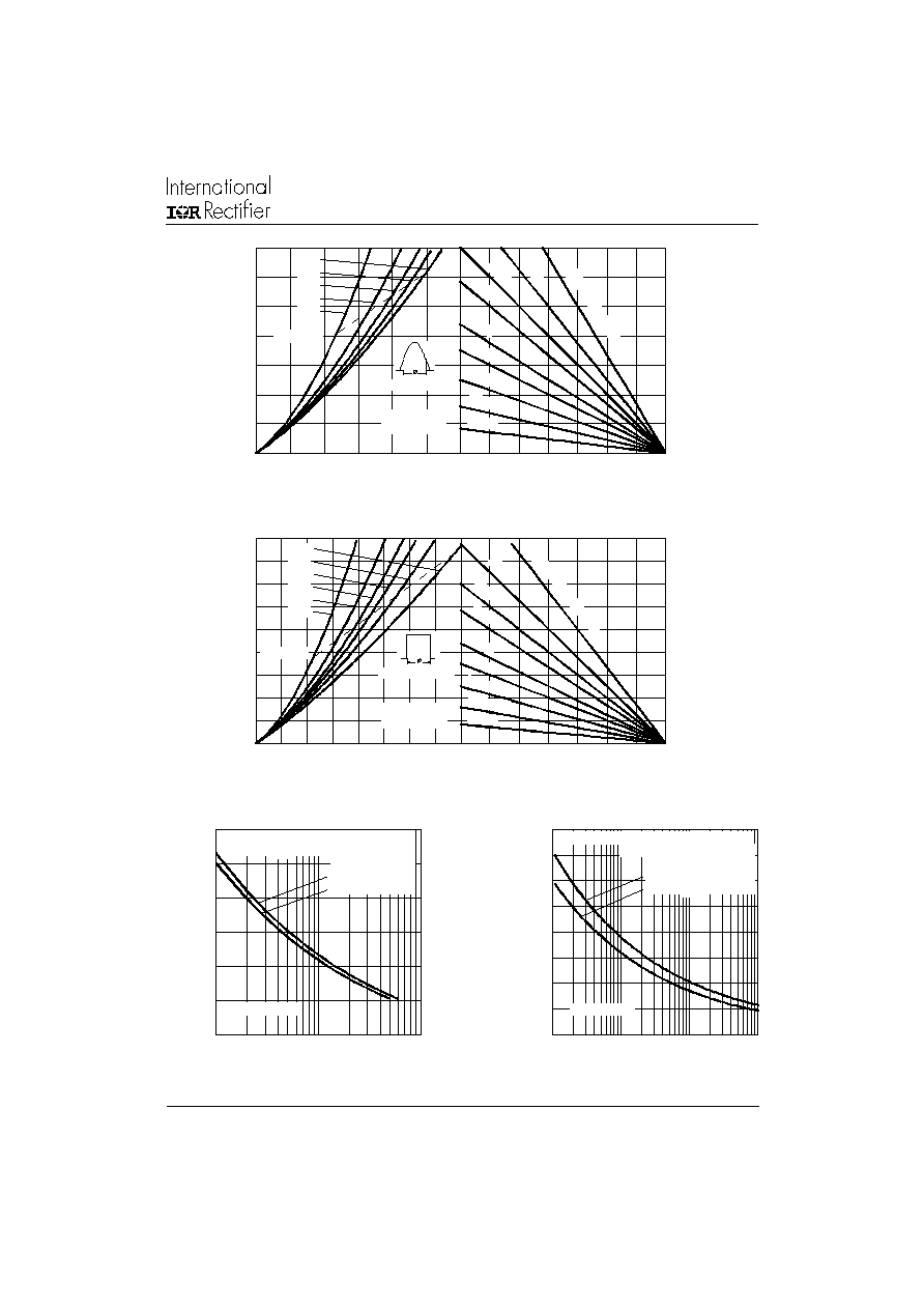
Fig. 1 - Current Ratings Characteristics
Fig. 2 - Current Ratings Characteristics
100
110
120
130
140
150
160
170
180
0
5
10
15
20
25
30
30∞
60∞
90∞
120∞
180∞
M
a
x
i
m
u
m
A
l
l
o
w
a
b
l
e C
a
s
e
T
e
m
p
er
at
ur
e (
∞C
)
Conduction Angle
Average Forward Current (A)
25F(R) Series
R (DC) = 1.5 K/W
thJC
100
110
120
130
140
150
160
170
180
0
5
10
15
20
25
30
35
40
45
DC
30∞
60∞
90∞
120∞
180∞
Ma
x
i
mu
m
A
l
l
o
w
a
b
l
e
C
a
s
e
T
e
mp
e
r
a
t
u
r
e
(
∞C
)
Conduction Period
Average Forward Current (A)
25F(R) Series
R (DC) = 1.5 K/W
thJC
Case Style DO-203AA (DO-4)
All dimensions in millimeters (inches)
25F(R) Series
5
Bulletin I2018 rev. B 09/98
www.irf.com
Fig. 3 - Forward Power Loss Characteristics
0
25
50
75
100
125
150
175
Maximum Allowable Ambient Temperature (∞C)
R
=
1
K
/W
-
D
el
ta
R
th
S
A
2 K
/W
3 K
/W
4 K
/W
6 K
/W
8 K
/W
12 K/W
20 K/W
40 K/W
0
5
10
15
20
25
30
35
0
5
10
15
20
25
30
Average Forward Current (A)
RMS Limit
M
a
x
i
m
u
m
A
v
e
r
ag
e F
o
r
w
a
r
d P
o
w
e
r
Lo
s
s
(
W
)
Conduction Angle
180∞
120∞
90∞
60∞
30∞
25F(R) Series
T = 175∞C
J
Fig. 4 - Forward Power Loss Characteristics
0
25
50
75
100
125
150
175
Maximum Allowable Ambient Temperature (∞C)
R
=
1
K
/W
- D
elt
a R
2 K
/W
3 K
/W
4 K/
W
6 K
/W
12 K/W
8 K/
W
20 K/W
40 K/W
th
S
A
0
5
10
15
20
25
30
35
40
45
0
5
10
15
20
25
30
35
40
DC
180∞
120∞
90∞
60∞
30∞
Average Forward Current (A)
RMS Limit
M
a
x
i
m
u
m
A
v
er
ag
e F
o
r
w
ar
d
P
o
w
e
r
L
o
s
s
(
W
)
Conduction Period
25F(R) Series
T = 175∞C
J
Fig. 5 - Maximum Non-Repetitive Surge Current
Fig. 6 - Maximum Non-Repetitive Surge Current
50
100
150
200
250
300
350
1
10
100
P
e
ak
H
a
l
f
S
i
n
e
W
a
v
e
F
o
r
w
ar
d C
u
r
r
ent
(
A
)
Number Of Equal Amplitude Half Cycle Current Pulses (N)
Initial T = 175∞C
@ 60 Hz 0.0083 s
@ 50 Hz 0.0100 s
At Any Rated Load Condition And With
Rated V Applied Following Surge.
RRM
J
25F(R) Series
0
50
100
150
200
250
300
350
400
0.01
0.1
1
10
P
e
a
k
H
a
l
f
S
i
n
e
Wav
e
F
o
r
w
ar
d C
u
r
r
en
t
(
A
)
Pulse Train Duration (s)
Maximum Non Repetitive Surge Current
Initial T = 175∞C
No Voltage Reapplied
Rated V Reapplied
Versus Pulse Train Duration.
J
RRM
25F(R) Series