 | –≠–ª–µ–∫—Ç—Ä–æ–Ω–Ω—ã–π –∫–æ–º–ø–æ–Ω–µ–Ω—Ç: 302UR030A | –°–∫–∞—á–∞—Ç—å:  PDF PDF  ZIP ZIP |
Features
Alloy diode
Popular series for rough service
Stud cathode and stud anode version
Typical Applications
Welders
Power supplies
Motor controls
Battery chargers
General industrial current rectification
I
F(AV)
300
A
@ T
C
150
∞C
I
FSM
@
50Hz
6550
A
@ 60Hz
6850
A
I
2
t
@
50Hz
214
KA
2
s
@ 60Hz
195
KA
2
s
V
RRM
range
100 to 600
V
T
J
-65 to 200
∞C
Parameters
300U
Units
Major Ratings and Characteristics
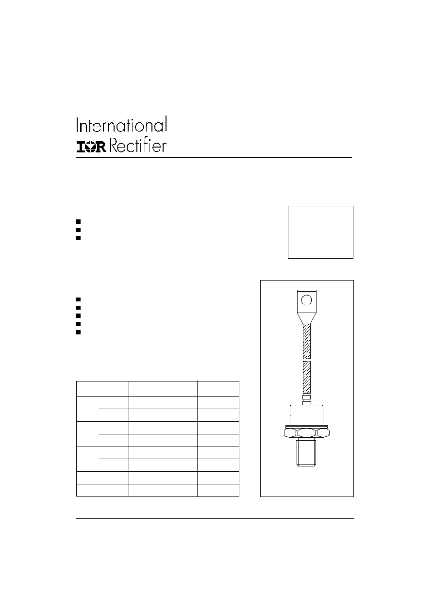
case style
DO-205AB (DO-9)
1
STANDARD RECOVERY DIODES
Stud Version
300U(R) SERIES
300A
Bulletin I2039 rev.
C
03/03
www.irf.com
300U(R) Series
2
www.irf.com
Bulletin I2039 rev.
C
03/03
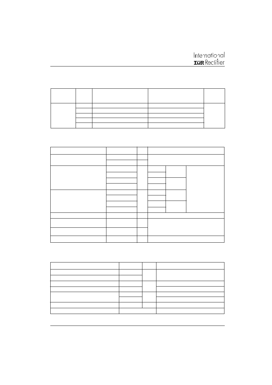
Voltage
V
RRM
, maximum repetitive
V
RSM
, maximum non-
I
RRM
max.
Type number
Code
peak reverse voltage
repetitive peak rev. voltage
T
J
= 175∞C
V
V
mA
10
100
200
20
200
300
300U
30
300
400
40
40
400
500
60
600
700
T
J
Max. junction operating temperature range
-65 to 200
T
stg
Max. storage temperature range
-65 to 200
R
thJC
Max. thermal resistance, junction to case
0.18
DC operation
R
thCS
Max. thermal resistance, case to heatsink
0.08
Mounting surface, smooth, flat and greased
T
Max. allowed mounting torque +0 -20%
37
Not lubricated threads
28
Lubricated threads
wt
Approximate weight
250
g
Case style
DO-205AB (DO-9)**
JEDEC (See Outline Table)
Parameter
300U(R)
Units
Conditions
Thermal and Mechanical Specifications
∞C
K/W
Nm
** 302U-A uses IR case style B-26
ELECTRICAL SPECIFICATIONS
Voltage Ratings
I
F(AV)
Max. average forward current
300
A
180∞ conduction, half sine wave
@ Case temperature
130
∞C
I
FSM
Max. peak, one-cycle forward,
6550
t = 10ms
No voltage
non-repetitive surge current
6850
t = 8.3ms
reapplied
5500
t = 10ms
100% V
RRM
5750
t = 8.3ms
reapplied
Sinusoidal half wave,
I
2
t
Maximum I
2
t for fusing
214
t = 10ms
No voltage
Initial T
J
= T
J
max.
195
t = 8.3ms
reapplied
151
t = 10ms
100% V
RRM
138
t = 8.3ms
reapplied
I
2
t
Maximum I
2
t for fusing
2140
KA
2
s
t = 0.1 to 10ms, no voltage reapplied
V
F(TO)
Max. value of threshold
voltage
r
f
Max. value of forward slope
resistance
V
FM
Max. peak forward voltage
1.40
V
I
peak
= 942A, T
J
= 25∞C
Parameter
300U
Units
Conditions
Forward Conduction
KA
2
s
A
0.610
V
0.751
m
T
J
= 200∞C
300U(R) Series
3
www.irf.com
Bulletin I2039 rev.
C
03/03
180∞
0.020
0.015
T
J
= T
J
max.
120∞
0.024
0.025
90∞
0.031
0.034
60∞
0.045
0.047
30∞
0.077
0.077
Conduction angle Sinusoidal conduction Rectangular conduction Units
Conditions
K/W
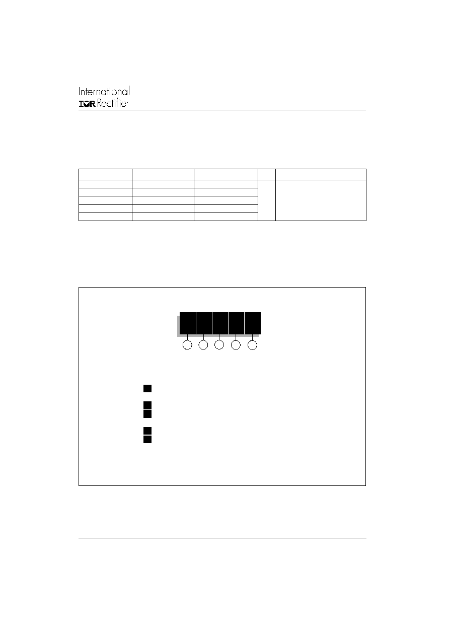
Ordering Information Table
300
U
R
060 A
1
2
3
4
5
Device Code
1
- 300
= Standard 300U device
302
= 300U Top Threaded version
2
- U
= Essential Part Number
3
- R
= Stud Reverse Polarity (Anode to Stud)
None
= Stud Normal Polarity (Cathode to Stud)
4
- Voltage code: Code x 10 = V
RRM
(See Voltage Ratings table)
5
- A
= Essential Part Number
NOTE: For Metric Device M16 x 1.5 Contact Factory
R
thJC
Conduction
(The following table shows the increment of thermal resistence R
thJC
when devices operate at different conduction angles than DC)
300U(R) Series
4
www.irf.com
Bulletin I2039 rev.
C
03/03
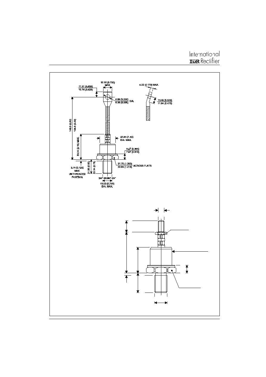
28.45 (1.12)
MAX.
27.94 (1.10) DIA. MAX.
3/4"-16UNF-2A
19.02 (0.749)
DIA. MAX.
9.27 (0.365)
7.87 (0.310)
31.75 (1.250) max.
ACROSS FLATS
16.51 (0.65)
14.99 (0.59)
ACROSS FLATS
18.29 (0.72)
16.76 (0.66)
9.50 (0.374) MAX. DIA.
3/8"-24UNF-2A
21.03 (0.828)
20.14 (0.793)
3.18 (0.125)
MAX.
58.67 (2.31)
55.63 (2.19)
Outline Table
300U-A Series
Conforms to JEDEC DO-205AB (DO-9)
All dimensions in millimeters (inches)
302U-A Series
IR Case Style B26
All dimensions in millimeters (inches)
* FOR METRIC DEVICE: M16 X 1.5
CONTACT FACTORY
300U(R) Series
5
www.irf.com
Bulletin I2039 rev.
C
03/03
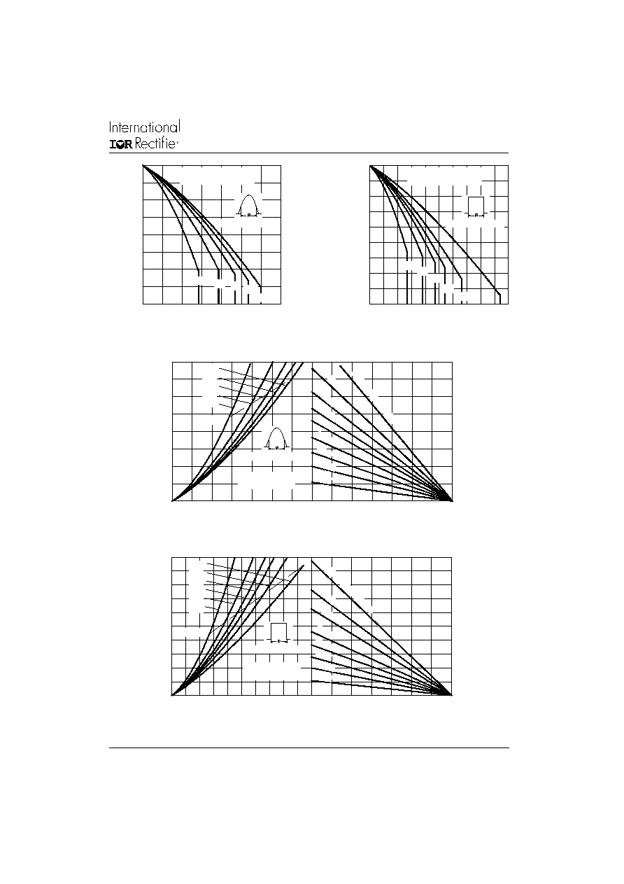
Fig. 2 - Current Ratings Characteristics
Fig. 1 - Current Ratings Characteristics
110
120
130
140
150
160
170
180
190
200
0
100
200
300
400
500
DC
30∞
60∞
90∞
120∞
180∞
Ma
x
i
m
u
m
Al
l
o
w
a
b
l
e
C
a
s
e
T
e
mp
e
r
a
t
u
r
e
(
∞
C
)
Conduc tion Period
Average Forward Current (A)
300U(R) Series
R (DC) = 0.18 K/ W
thJC
120
140
160
180
200
0
50
100 150 200 250 300 350
30∞
60∞ 90∞
120∞
180∞
M
a
x
i
mum
A
l
l
o
w
a
b
l
e C
a
s
e
T
e
mp
e
r
a
t
u
r
e
(
∞
C)
Conduction Angle
Average Forward Current (A)
300U(R) Series
R (DC) = 0.18 K/ W
thJC
Fig. 3 - Forward Power Loss Characteristics
Fig. 4 - Forward Power Loss Characteristics
25
50
75
100 125 150 175 200
Maximum Allowable Ambient Temperature (∞C)
3 K/ W
1.5 K/ W
1 K/ W
0.7 K
/ W
0.5 K
/ W
0.4
K/W
0.3
K/
W
R
=
0
.1
K
/W
- D
elt
a R
0.2
K/
W
th
SA
350
0
50
100
150
200
250
300
350
400
0
50
100 150 200 250 300
RMS Limit
180∞
120∞
90∞
60∞
30∞
Conduc tion Angle
M
a
x
i
mu
m
A
v
er
a
g
e F
o
r
w
a
r
d
P
o
w
e
r
L
o
s
s
(
W
)
Average Forward Current (A)
300U(R) Series
T = 200∞C
J
25
50
75
100 125 150 175 200
Maximum Allowable Ambient Temperature (∞C)
3 K/W
1.5 K/W
1 K/W
0.7 K
/ W
0.3
K/W
0.2
K/
W
R
=
0
.1 K
/ W
- D
elt
a R
th
SA
0.5 K
/ W
500
0
50
100
150
200
250
300
350
400
450
500
0
100
200
300
400
DC
180∞
120∞
90∞
60∞
30∞
RMS Limit
Conduction Period
Average Forward Current (A)
M
a
x
i
m
u
m
A
v
e
r
age
F
o
r
w
ar
d P
o
w
e
r
L
o
s
s
(
W
)
300U(R) Series
T = 200∞C
J