 | –≠–ª–µ–∫—Ç—Ä–æ–Ω–Ω—ã–π –∫–æ–º–ø–æ–Ω–µ–Ω—Ç: 30BF80 | –°–∫–∞—á–∞—Ç—å:  PDF PDF  ZIP ZIP |

SURFACE MOUNTABLE
ULTRAFAST RECOVERY DIODE
1
PD-20713 07/99
30BF.. Series
Major Ratings and Characteristics
Characteristics
30BF..
Units
10 to 20
40
60 to 80
I
F(AV)
3
A
V
RRM
100 to 800
V
I
FSM
100
A
V
F
@
3 A, T
J
= 25∞C
1.0
1.4
1.7
V
t
rr
@ T
J
= 25∞C
50
50
100
ns
T
J
range
- 50 to 150
∞C
Features
For surface mounted applications
Low profile package
Built in stress releaf
Compatible with all pick & palce equipments
Ultrafast recovery times for high efficiency
Plastic package has Underwriters Laboratory
Flammability Classification 94V-O
Glass passivated junction
High temperature soldering:
260∞C\10 seconds at terminals
Dimensions in inches and (millimeters)
.220 (5.59)
.245 (6.22)
.260 (6.60)
.280 (7.11)
.108 (2.75)
.124 (3.15)
.006 (.152)
.012 (.305)
.079 (2.00)
.103 (2.62)
.030 (0.76)
.060 (1.52)
.004 (.103)
.008 (.203)
.305 (7.75)
.320 (8.13)
SMC (DO-214AB)
2
30BF.. Series
PD-20713 07/99
V
RRM
, maximum
V
DC
, maximum
I
RRM
Part Number
peak reverse voltage
blocking voltage
100∞C
V
V
µA
30BF10
100
100
500
30BF20
200
200
30BF40
400
400
30BF60
600
600
30BF80
800
800
I
F(AV)
Maximum Average Forward Current
3
A
@ T
L
= 75∞ C
I
FSM
Peak Forward Surge Current
100
A
8.3ms single half sine wave superimposed
on rated load (JEDEC Method) T
A
= 55∞ C
V
FM
Max. Instantaneous Forward Voltage
1.0
1.4
1.7
V
@ 3A
I
RM
Maximum DC Reverse Current
10
µA
T
A
= 25∞ C
at Rated DC Blocking Voltage
500
T
A
= 100∞ C
t
rr
Reverse Recovery Time
50
50
100
ns
I
F
= 0.5A, I
R
= 1.0A, I
rr
= 0.25A
C
J
Typical Junction Capacitance
75
75
50
pf
@ 1.0MHz applied reverse voltage of 4.0 V
Voltage Ratings
Maximum Ratings and Electrical Characteristics
Parameters
30BF..
Units
Conditions
10 to 20
40
60 to 80
Ratings at 25∞C ambient temperature unless otherwise specified.
Resistive or inductive load.
For capacitive load, derate current by 20%.
R
thJ
Maximum Thermal Resistance
15
∞C/W 8.0mm
2
(.013mm thick) land areas
T
J
Operating Temperature Range
- 50 to 150
∞C
T
stg
Storage Temperature Range
- 50 to 150
∞C
wt
Approximate Weight
0.21 (0.007)
g (oz)
Case Style
DO-214AB
JEDEC molded plastic
Mechanical Specifications
Parameters
30BF..
Units
Conditions

3
30BF..
Series
PD-20713 07/99
Fig. 1 - Maximum Average Forward Current Rating
50
60
70
80
90
100
110
120
130
140
150
0
0.5
1
1.5
2
2.5
3
3.5
Average Forward Current (A)
Le
ad T
e
m
p
e
r
at
ur
e
(
∞
C
)
30BF.. Series
Fig. 3 - Typical Forward Characteristics
Fig. 4 - Max. Non-Repetitive Forward Surge Characteristic
Fig. 2 - Typical Reverse Characteristics
0.01
0.1
1
10
100
0.4
0.6
0.8
1
1.2
1.4
1.6
1.8
I
n
st
ant
a
ne
o
u
s
F
o
r
w
ar
d C
u
r
r
e
nt
(
A
)
Instantaneous Forward Voltage (V)
T = 25∞C
Pulse Width = 300µs
2% Duty Cicle
J
30BF10/20
30BF40
30BF60/80
10
100
1
10
100
P
e
ak
F
o
r
w
ar
d
S
u
r
g
e
C
u
r
r
e
n
t
(
A
)
Number of Cycles at 60 Hz
8.3ms Single Half Sine Wave
Jedec Method
30BF.. Series
20
40
60
80
100
120
140
160
0.1
1
10
100
1000
Ca
p
a
c
i
t
a
n
c
e
(
p
F
)
Reverse Voltage (V)
T = 25∞C
f = 1MHz
Vsig = 50mVp-p
30BF10/20
30BF40/60/80
J
Fig. 5 - Typical Junction Capacitance
0.1
1
10
100
0
20
40
60
80
100
120
140
T = 25∞C
J
I
n
st
an
t
a
n
e
o
u
s Re
v
e
r
s
e
Le
ak
ag
e
C
u
r
r
e
n
t
(
µ
A
)
Percent of Peak Reverse Voltage (V)
T = 150∞C
T = 100∞C
J
J
30BF.. Series
PU LSE
GENERATOR
NOTE 2
OSCILLOSCOPE
NOTE 1
1 S
NON
INDUCTIVE
10 S
NON
INDUCTIVE
50 S
NON
INDUCTIVE
25V d c
(approx)
(+)
(+)
(-)
(-)
D.U.T.
1cm
SET TIME
BASE FOR
1 0nsec/cm
+0.5A
0
-1 A
-0.25 A
trr
Reverse Recovery Time Characteristic
and Test Circuit Diagram
4
30BF.. Series
PD-20713 07/99
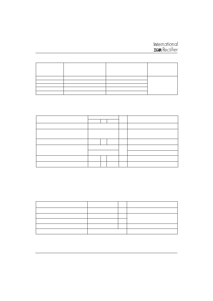
Ordering Information Table
30
B
F
80
Device Code
1
2
4
3
1
-
Current Rating x 10: 30 = 3A
2
-
B = DO-214AB (SMC) Surface Mount
3
-
F = Ultrafast Recovery
4
-
Voltage code: Code = V
RRM
/ 10
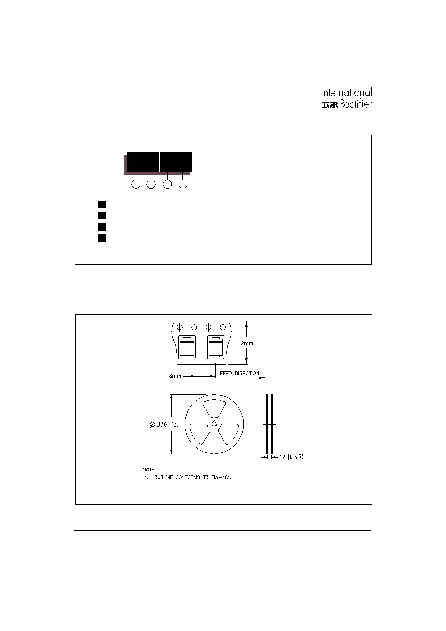
Tape & Reel Information
Dimensions in millimeters and (inches)