 | –≠–ª–µ–∫—Ç—Ä–æ–Ω–Ω—ã–π –∫–æ–º–ø–æ–Ω–µ–Ω—Ç: 30DPS | –°–∫–∞—á–∞—Ç—å:  PDF PDF  ZIP ZIP |

GLASS PASSIVATED
PLASTIC RECTIFIER
SAFE
IR
Series
30DPS..
1
Bulletin I2103 rev. B 07/97
I
F(AV)
= 30 Amp
I
FSM
= 300 Amp
V
RRM
up to 1200V
150∞ C T
J
operation
Glass Passivated chip junction
Low forward voltage drop
High Current Capabilities
High Surge Current Capabilities
SMD Series Available
I
F(AV)
Sinusoidal
waveform
V
RRM
800 to 1200
V
I
FSM
300
A
V
FM
@
30 A
pk
, T
J
= 25∞C
1.15
V
T
J
- 40 to 150
∞C
Characteristics
30DPS..
Units
30
A
Major Ratings and Characteristics
TO-247AC
Description/Features
The 30DPS rectifier
SAFE
IR
series has been optimized
for very low forward voltage drop, with moderate leakage.
The glass passivation technology used has reliable opera-
tion up to 150∞ C junction temperature.
Typical applications are in input rectification.
Package Outline

2
30DPS..
SAFE
IR
Series
Bulletin I2103 rev. B 07/97
Type number
Voltage Ratings
V
RRM
, maximum
V
RSM
, maximum
I
RRM
Code
peak reverse voltage
peak reverse voltage
150∞C
-
V
V
mA
30DPS..
08
800
900
1
12
1200
1300
I
F(AV)
Max. Average Forward Current
30
A
@ T
C
= 90∞ C, 180∞ conduction half sine wave
I
FSM
Max. Peak One Cycle Non-Repetitive
250
A
10ms Sine pulse, rated V
RRM
applied
Surge Current Per Junction
300
10ms Sine pulse, no voltage reapplied
I
2
t
Max. I
2
t for fusing
316
A
2
s 10ms Sine pulse, rated V
RRM
applied
442
10ms Sine pulse, no voltage reapplied
I
2
t
Max. I
2
t for fusing
4420
A
2
s t = 0.1 to 10ms, no voltage reapplied
Absolute Maximum Ratings
Parameters
30DPS.. Units
Conditions
V
FM
Max. Forward Voltage Drop
1.15
V
@ 30A, T
J
= 25∞C
r
t
Forward slope resistance
9.28
m
V
F(TO)
Threshold voltage
0.78
V
I
RM
Max. Reverse Leakage Current
0.1
mA
T
J
= 25 ∞C
V
R
= rated V
RRM
1.0
T
J
= 150 ∞C
Electrical Specifications
Parameters
30DPS.. Units
Conditions
T
J
= 150∞C
T
J
Max. Junction Temperature Range
- 40 to 150
∞C
T
stg
Max. Storage Temperature Range
- 40 to 150
∞C
R
thJC
Max. Thermal Resistance Junction
40
∞C/W
to Ambient
R
thJA
Max. Thermal Resistance Junction
0.95
∞C/W
DC operation, per junction
to Case
R
thCS
Typical Thermal Resistance, Case to
0.2
∞C/W
Mounting surface , smooth and greased
Heatsink
wt
Approximate Weight
6 (0.21)
g (oz.)
T
Mounting Torque
Min.
6 (5)
Max.
12 (10)
Case Style
TO-247AC
JEDEC
Thermal-Mechanical Specifications
Parameters
30DPS..
Units
Conditions
Kg-cm
(Ibf-in)
Provide terminals coating for voltages above 1200V

3
30DPS..
SAFE
IR
Series
Bulletin I2103 rev. B 07/97
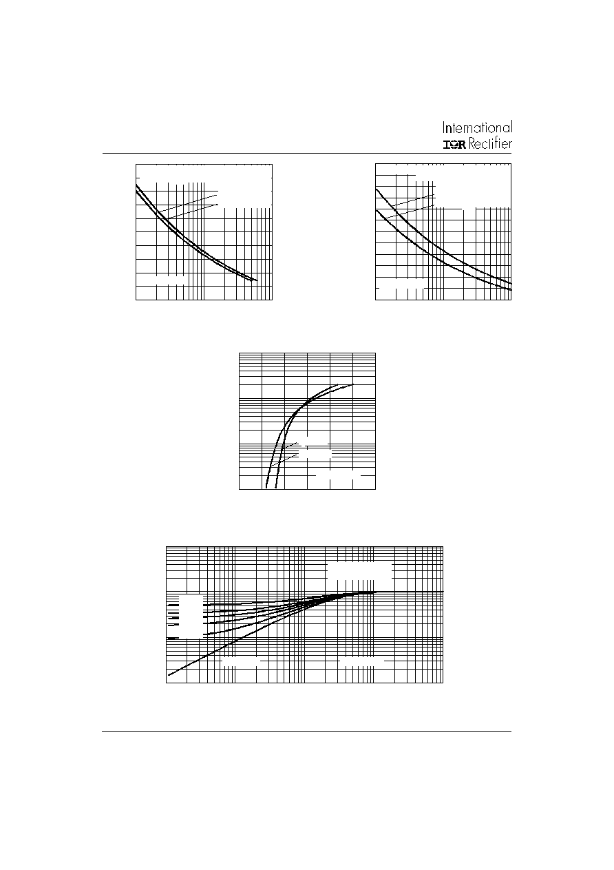
Fig. 1 - Current Rating Characteristics (Per Junction)
Fig. 2 - Current Rating Characteristics (Per Junction)
Fig. 3 - Forward Power Loss Characteristics
(Per Junction)
0
20
40
60
80
100
120
140
0
10
20
30
40
50
Total Output Current (A)
M
a
x
i
mu
m T
o
ta
l
P
o
w
e
r
L
o
s
s
(
W
)
180∞
(Sine)
180∞
(Rect)
30DPS.. Series
Single Phase Bridge
Connected
T = 150∞C
J
0
20
40
60
80
100
120
140
0
10
20
30
40
50
Total Output Current (A)
M
a
x
i
mu
m
T
o
ta
l
P
o
w
e
r
L
o
s
s
(
W
)
120∞
(Rect)
30DPS.. Series
Three Phase Bridge
Connected
T = 150∞C
J
80
90
100
110
120
130
140
150
0
5
10
15
20
25
30
35
30∞
60∞
90∞
120∞
180∞
Average Forward Current (A)
Conduction Angle
M
a
x
i
mu
m
A
l
l
o
w
a
b
l
e
C
a
s
e
T
e
mp
e
r
a
t
u
r
e
(
∞C
)
30DPS.. Series
R (DC) = 1 K/W
thJ C
80
90
100
110
120
130
140
150
0
10
20
30
40
50
DC
30∞
60∞
90∞
120∞
180∞
Conduction Period
M
a
x
i
m
u
m
A
l
l
o
w
a
b
l
e
C
a
s
e
T
e
m
p
er
a
t
u
r
e
(
∞C
)
Average Forward Current (A)
30DPS.. Series
R (DC) = 1 K/W
thJ C
Fig. 5 - Forward Power Loss Characteristics
Fig. 6 - Forward Power Loss Characteristics
Fig. 4 - Forward Power Loss Characteristics
(Per Junction)
0
10
20
30
40
50
0
5
10
15
20
25
30
35
180∞
120∞
90∞
60∞
30∞
RMS Limit
Conduction Angle
M
a
x
i
m
u
m
A
v
e
r
ag
e
F
o
r
w
ar
d
P
o
we
r
Lo
ss (
W
)
Average Forward Current (A)
30DPS.. Series
T = 150∞C
J
0
10
20
30
40
50
60
0
10
20
30
40
50
DC
180∞
120∞
90∞
60∞
30∞
RMS Limit
Conduction Period
M
a
x
i
mu
m A
v
e
r
a
g
e
F
o
r
w
a
r
d
P
o
w
e
r
L
o
s
s
(
W
)
Average Forward Current (A)
30DPS.. Series
T = 150∞C
J
4
30DPS..
SAFE
IR
Series
Bulletin I2103 rev. B 07/97
50
100
150
200
250
300
1
10
100
P
e
a
k
H
a
l
f
S
i
n
e
W
a
v
e
F
o
rw
a
r
d
C
u
rre
n
t
(
A
)
Number Of Equal Amplitude Half Cycle Current Pulses (N)
Initial T = 150 ∞C
@ 60 Hz 0.0083 s
@ 50 Hz 0.0100 s
At Any Rated Load Condition And With
Rated V Applied Following Surge.
RRM
J
30DPS.. Series
50
100
150
200
250
300
350
0.01
0.1
1
P
e
ak
Hal
f
S
i
ne
W
a
v
e
F
o
r
w
ar
d
C
u
r
r
e
nt
(
A
)
Initial T = 150 ∞C
No Voltage Reapplied
Rated V Reapplied
Pulse Train Duration (s)
RRM
Versus Pulse Train Duration.
Maximum Non Repetitive Surge Current
J
30DPS.. Series
0.01
0.1
1
10
0.0001
0.001
0.01
0.1
1
Square Wave Pulse Duration (s)
th
J
C
T
r
a
n
s
i
en
t
Th
e
r
m
a
l I
m
p
e
d
a
n
c
e Z
(
K
/
W
)
Steady State Value
(DC Operation)
D = 0.50
D = 0.33
D = 0.25
D = 0.17
D = 0.08
30DPS.. Series
Single Pulse
Fig. 10 - Thermal Impedance Z
thJC
Characteristics (Per Junction)
Fig. 9 - Forward Voltage Drop Characteristics
(Per Junction)
1
10
100
1000
0
0.5
1
1.5
2
2.5
3
T = 25∞C
J
Instantaneous Forward Voltage (V)
I
nst
ant
a
ne
o
u
s F
o
r
w
a
r
d
C
u
r
r
e
n
t
(
A
)
T = 150∞C
J
30DPS.. Series
Fig. 7 - Maximum Non-Repetitive Surge Current
(Per Junction)
Fig. 8 - Maximum Non-Repetitive Surge Current
(Per Junction)

5
30DPS..
SAFE
IR
Series
Bulletin I2103 rev. B 07/97
30
D
P
S
12
Device Code
1
5
2
4
3
1
-
Part Code
2
-
Circuit Configuration:
D = Half Bridge Configuration
3
-
Package:
P = TO-247AC
4
-
Type of Silicon:
S = Silicon Recovery Rectifier
5
-
Voltage code: Code x 100 = V
RRM
(See Voltage Ratings table)
6
Ordering Information Table
Ordering Information Table
Dimensions in millimeters and inches
15.90 (0.626)
15.30 (0.602)
14.20 (0.559)
14.80 (0.583)
3.70 (0.145)
4.30 (0.170)
5.30 (0.208)
5.70 (0.225)
5.50 (0.217)
4.50 (0.177)
(2 PLCS.)
3.55 (0.139)
3.65 (0.144)
2.20 (0.087)
MAX.
1.00 (0.039)
1.40 (0.056)
3.20 (0.126)
MAX.
0.40 (0.213)
0.80 (0.032)
4.70 (0.185)
5.30 (0.209)
1.5 (0.059)
2.5 (0.098)
2.40 (0.095)
MAX.
5.43 (0.213)
5.47 (0.216)
20.30 (0.800)
19.70 (0.775)
1 2 3
DIA.
1
3
2
BASE
COMMON