FAST SOFT RECOVERY
RECTIFIER DIODE
1
Bulletin I2129 rev. A 06/98
V
F
< 1.25V @ 20A
t
rr
= 95 ns
V
RRM
1000 to 1200V
QUIET
IR
Series
40EPF.. HV
I
F(AV)
Sinusoidal waveform
40
A
V
RRM
1000 to 1200
V
I
FSM
475
A
V
F
@
20 A, T
J
= 25�C
1.25
V
trr
@ 1A, - 100A/�s
95
ns
T
J
- 40 to 150
�C
Major Ratings and Characteristics
Characteristics
40EPF..
Units
Description/Features
The 40EPF.. fast soft recovery
QUIET
IR
rectifier
series has been optimized for combined short
reverse recovery time and low forward voltage
drop.
The glass passivation ensures stable reliable
operation in the most severe temperature and
power cycling conditions.
Typical applications are both:
output rectification and freewheeling in
inverters, choppers and converters
and input rectifications where severe
restrictions on conducted EMI should be met.
TO-247AC (Modified)
Package Outline
2
40EPF.. HV
QUIET
IR
Series
Bulletin I2129 rev. A 06/98
I
F(AV)
Max. Average Forward Current
40
A
@ T
C
= 105� C, 180� conduction half sine wave
I
FSM
Max. Peak One Cycle Non-Repetitive
400
10ms Sine pulse, rated V
RRM
applied
Surge Current
475
10ms Sine pulse, no voltage reapplied
I
2
t
Max. I
2
t for fusing
800
10ms Sine pulse, rated V
RRM
applied
1131
10ms Sine pulse, no voltage reapplied
I
2
t
Max. I
2
t for fusing
11310
A
2
s
t = 0.1 to 10ms, no voltage reapplied
Part Number
Voltage Ratings
Absolute Maximum Ratings
Electrical Specifications
Recovery Characteristics
Parameters
40EPF..
Units
Conditions
A
A
2
s
V
FM
Max. Forward Voltage Drop
1.4
V
@ 40A, T
J
= 25�C
r
t
Forward slope resistance
6.82
m
V
F(TO)
Threshold voltage
0.94
V
I
RM
Max. Reverse Leakage Current
0.1
T
J
= 25 �C
10
T
J
= 150 �C
Parameters
40EPF..
Units
Conditions
T
J
= 125�C
V
R
= rated V
RRM
mA
t
rr
Reverse Recovery Time
450
ns
I
F
@ 10Apk
I
rr
Reverse Recovery Current
6
A
@ 25A/ �s
Q
rr
Reverse Recovery Charge
1.8
�C
@ 25�C
S
Typical Snap Factor
0.5
Parameters
40EPF..
Units
Conditions
V
RRM
, maximum
V
RSM
, maximum non repetitive
I
RRM
peak reverse voltage
peak reverse voltage
150�C
V
V
mA
40EPF10
1000
1100
10
40EPF12
1200
1300

3
40EPF.. HV
QUIET
IR
Series
Bulletin I2129 rev. A 06/98
T
J
Max. Junction Temperature Range
- 40 to 150
�C
T
stg
Max. Storage Temperature Range
- 40 to 150
�C
R
thJC
Max. Thermal Resistance Junction
0.6
�C/W
DC operation
to Case
R
thJA
Max. Thermal Resistance Junction
40
�C/W
to Ambient
R
thCS
Typical Thermal Resistance, Case to
0.2
�C/W
Mounting surface , smooth and greased
Heatsink
wt
Approximate Weight
6 (0.21)
g (oz.)
T
Mounting Torque
Min.
6 (5)
Max.
12 (10)
Case Style
TO-247AC
JEDEC (Modified)
Thermal-Mechanical Specifications
Parameters
40EPF..
Units
Conditions
Kg-cm
(Ibf-in)
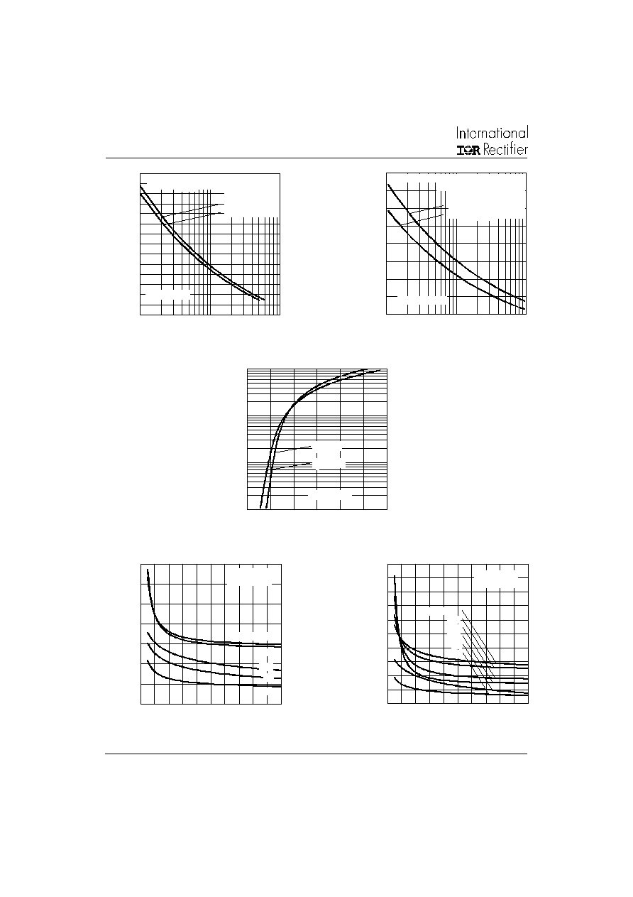
Fig. 1 - Current Rating Characteristics
Fig. 2 - Current Rating Characteristics
Fig. 3 - Forward Power Loss Characteristics
Fig. 4 - Forward Power Loss Characteristics
60
70
80
90
100
110
120
130
140
150
0
10
20
30
40
50
60
70
DC
30�
60�
90�
120�
180�
M
a
x
i
mu
m A
l
l
o
w
a
b
l
e
C
a
s
e
T
e
m
p
e
r
a
t
u
r
e
(
�C
)
Conduction Period
Average Forward Current (A)
40EPF.. Series
R (DC) = 0.6 �C/W
thJC
60
70
80
90
100
110
120
130
140
150
0
5
10
15
20
25
30
35
40
45
30�
60�
90�
120�
180�
M
a
x
i
m
u
m
A
l
lo
w
a
b
l
e C
a
s
e
Tem
p
er
a
t
u
r
e (
�C
)
Conduction Angle
Average Forward Current (A)
40EPF.. Series
R (DC) = 0.6 �C/W
thJC
0
10
20
30
40
50
60
70
0
5
10
15
20
25
30
35
40
45
RMS Limit
180�
120�
90�
60�
30�
Conduction Angle
Average Forward Current (A)
M
a
x
i
m
u
m
A
v
e
r
ag
e
F
o
r
w
ar
d P
o
we
r
Lo
ss (
W
)
40EPF.. Series
T = 150�C
J
0
10
20
30
40
50
60
70
80
90
0
10
20
30
40
50
60
70
DC
180�
120�
90�
60�
30�
RMS Limit
Conduction Period
Average Forward Current (A)
M
a
x
i
m
u
m
A
v
e
r
ag
e
F
o
r
w
ar
d
P
o
we
r
Lo
ss (
W
)
40EPF.. Series
T = 150�C
J
4
40EPF.. HV
QUIET
IR
Series
Bulletin I2129 rev. A 06/98
Fig. 5 - Maximum Non-Repetitive Surge Current
Fig. 6 - Maximum Non-Repetitive Surge Current
Fig. 7 - Forward Voltage Drop Characteristics
Fig. 9 - Recovery Time Characteristics, T
J
= 150�C
Fig. 8 - Recovery Time Characteristics, T
J
= 25�C
100
150
200
250
300
350
400
450
1
10
100
Number Of Equal Amplitude Half Cycle Current Pulses (N)
P
e
ak
Ha
l
f
S
i
n
e
W
a
v
e
F
o
r
w
ar
d C
u
r
r
e
n
t
(
A
)
Initial T = 150�C
@ 60 Hz 0.0083 s
@ 50 Hz 0.0100 s
J
At Any Rated Load Condition And With
Rated V Applied Following Surge.
RRM
40EPF.. Series
100
150
200
250
300
350
400
450
500
0.01
0.1
1
Pulse Train Duration (s)
P
e
a
k
Hal
f
S
i
ne
W
a
v
e
F
o
r
w
ar
d
C
u
r
r
e
nt
(
A
)
Versus Pulse Train Duration.
Initial T = 150�C
No Voltage Reapplied
Rated V Reapplied
RRM
J
Maximum Non Repetitive Surge Current
40EPF.. Series
1
10
100
1000
0
1
2
3
4
5
6
T = 25�C
J
I
n
st
ant
a
ne
o
u
s F
o
r
w
a
r
d C
u
r
r
e
n
t
(
A
)
Instantaneous Forward Voltage (V)
T = 150�C
J
40EPF.. Series
0
0.4
0.8
1.2
1.6
2
0
40
80
120
160
200
Rate Of Fall Of Forward Current - di/dt (A/�s)
1 A
5 A
10 A
M
a
xi
m
u
m
R
e
ve
r
s
e
R
e
c
o
ve
r
y
T
i
m
e
- T
r
r
(
�s)
40EPF.. Series
T = 150�C
J
I = 60 A
FM
20 A
40 A
0
0.1
0.2
0.3
0.4
0.5
0.6
0.7
0
40
80
120
160
200
Rate Of Fall Of Forward Current - di/dt (A/�s)
1 A
5 A
10 A
M
a
x
i
m
u
m
R
e
v
e
rs
e
R
e
c
o
v
e
ry
T
i
m
e
-
T
rr (
�s
)
40EPF.. Series
T = 25�C
J
30 A
I = 40 A
FM

5
40EPF.. HV
QUIET
IR
Series
Bulletin I2129 rev. A 06/98
Fig. 10 - Recovery Charge Characteristics, T
J
= 25�C
Fig. 11 - Recovery Charge Characteristics, T
J
= 150�C
Fig. 12 - Recovery Current Characteristics, T
J
= 25�C
Fig. 13 - Recovery Current Characteristics, T
J
= 150�C
Fig. 14 - Thermal Impedance Z
thJC
Characteristics
0
1
2
3
4
5
6
0
40
80
120
160
200
Rate Of Fall Of Forward Current - di/dt (A/�s)
1 A
5 A
10 A
M
a
x
i
m
u
m
Re
v
e
r
s
e
Re
c
o
v
e
r
y
C
h
ar
g
e
-
Q
r
r
(
�C
)
I = 40 A
FM
30 A
40EPF.. Series
T = 25�C
J
0
4
8
12
16
20
0
40
80
120
160
200
Rate Of Fall Of Forward Current - di/dt (A/�s)
1 A
5 A
10 A
M
a
x
i
mu
m R
e
v
e
r
s
e
R
e
c
o
v
e
r
y
C
h
a
r
g
e
-
Q
r
r
(
�C
)
I = 60 A
40EPF.. Series
T = 150�C
J
FM
20 A
40 A
0
5
10
15
20
25
30
0
40
80
120
160
200
M
a
x
i
m
u
m
R
e
v
e
rs
e
R
e
c
o
v
e
ry
C
u
r
r
e
n
t
-
I
rr (
A
)
Rate Of Fall Of Forward Current - di/dt (A/�s)
1 A
5 A
10 A
40EPF.. Series
T = 25�C
J
I = 40 A
FM
30 A
0
10
20
30
40
50
0
40
80
120
160
200
M
a
x
i
m
u
m
R
e
v
e
rs
e
R
e
c
o
v
e
ry
C
u
r
r
e
n
t
-
Irr
(
A
)
Rate Of Fall Of Forward Current - di/dt (A/�s)
1 A
5 A
10 A
40EPF.. Series
T = 150�C
J
I = 60 A
FM
40 A
20 A
0.1
1
0.0001
0.001
0.01
0.1
1
10
Square Wave Pulse Duration (s)
Steady State Value
(DC Operation)
Single Pulse
th
J
C
T
r
a
n
s
i
en
t
T
h
er
m
a
l
I
m
p
e
d
a
n
c
e
Z
(
�C
/
W
)
D = 0.50
D = 0.33
D = 0.25
D = 0.17
D = 0.08
40EPF.. Series

6
40EPF.. HV
QUIET
IR
Series
Bulletin I2129 rev. A 06/98
Outline Table
Dimensions in millimeters and inches
Ordering Information Table
40
E
P
F
12
Device Code
1
5
2
4
3
1
-
Current Rating
2
-
Circuit Configuration:
E = Single Diode
3
-
Package:
P = TO-247AC (Modified)
4
-
Type of Silicon:
F = Fast Recovery
5
-
Voltage code: Code x 100 = V
RRM
6
10 = 1000V
12 = 1200V
15 .90 (0 .626)
15 .30 (0 .602)
14 .20 (0 .559)
14. 80 ( 0.583)
3. 70 ( 0.145)
4.30 ( 0.170)
5.30 ( 0.208)
5.70 ( 0.225)
5.50 ( 0.217)
4. 50 ( 0.177)
( 2 PLC S.)
3. 55 (0 .13 9)
3. 65 ( 0.14 4)
2. 20 (0 .08 7)
M AX .
1.00 ( 0 .03 9)
1.40 ( 0 .05 6)
0.40 ( 0 .21 3)
0.80 ( 0.032)
4.70 ( 0.185)
5.30 ( 0 .209)
1.5 ( 0.059)
2.5 ( 0.098)
2. 40 (0 .09 5)
M AX .
10.86 ( 0.427 )
10. 94 ( 0.430)
20 .30 (0 .800)
19 .70 (0 .775)
1 3
DIA.
1
CATHODE
ANODE
3
2
BASE
CATHODE