 | –≠–ª–µ–∫—Ç—Ä–æ–Ω–Ω—ã–π –∫–æ–º–ø–æ–Ω–µ–Ω—Ç: 40HF10 | –°–∫–∞—á–∞—Ç—å:  PDF PDF  ZIP ZIP |
Features
High surge current capability
Stud cathode and stud anode version
Leaded version available
Types up to 1600V V
RRM
Typical Applications
Battery charges
Converters
Power supplies
Machine tool controls
Welding
Parameters
Units
40HF(R)
10 to 120
140, 160
I
F(AV)
40
40
A
@ T
C
140
110
∞C
I
F(RMS)
62
A
I
FSM
@
50Hz
570
A
@ 60Hz
595
A
I
2
t
@
50Hz
1600
A
2
s
@ 60Hz
1450
A
2
s
V
RRM
range
100 to 1200
1400, 1600
V
T
J
range
- 65 to 190
- 65 to 160
∞C
Major Ratings and Characteristics
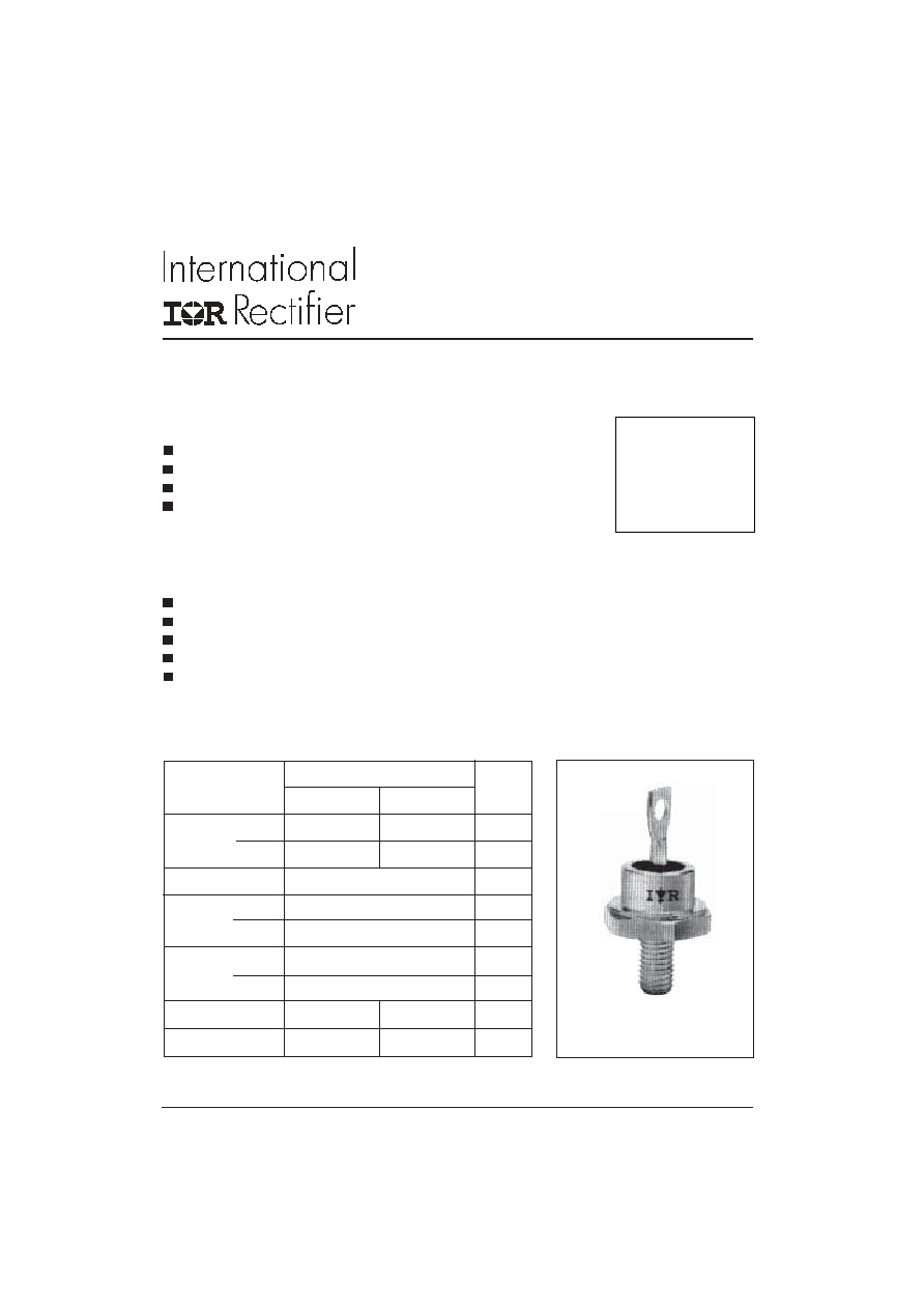
case style
DO-203AB (DO-5)
40HF(R) SERIES
STANDARD RECOVERY DIODES
40 A
1
Stud Version
Bulletin I20201 rev. C 03/04
www.irf.com
40HF(R) Series
2
Bulletin I20201 rev. C 03/04
www.irf.com
Parameter
Units Conditions
40HF(R)
10 to 120 140 , 160
Voltage
V
RRM
, maximum
V
RSM
, maximum non-
I
RRM
max.
Type number
Code
repetitive peak
repetitive peak
@ T
J
= T
J
max.
reverse voltage
reverse voltage
V
V
mA
10
100
200
9
20
200
300
40
400
500
40HF(R)
60
600
700
80
800
900
100
1000
1100
120
1200
1300
140
1400
1500
4.5
160
1600
1700
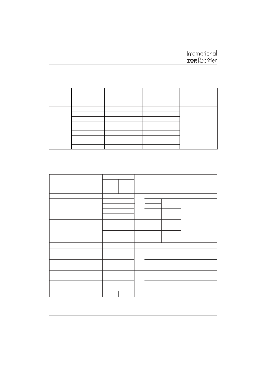
ELECTRICAL SPECIFICATIONS
Voltage Ratings
I
F(AV)
Max. average forward current
40
40
A
180∞ conduction, half sine wave
@ Case temperature
140
110
∞C
I
F(RMS)
Max. RMS forward current
62
A
I
FSM
Max. peak, one-cycle forward,
570
t = 10ms
No voltage
non-repetitive surge current
595
t = 8.3ms
reapplied
480
t = 10ms
100% V
RRM
500
t = 8.3ms
reapplied
Sinusoidal half wave,
I
2
t
Maximum I
2
t for fusing
1600
t = 10ms
No voltage
Initial T
J
= T
J
max.
1450
t = 8.3ms
reapplied
1150
t = 10ms
100% V
RRM
1050
t = 8.3ms
reapplied
I
2
t
Maximum I
2
t for fusing
16000
A
2
s
t = 0.1 to 10ms, no voltage reapplied
V
F(TO)
Value of threshold
voltage (up to 1200V)
V
F(TO)
Value of threshold
voltage (for 1400V, 1600V)
r
f
Value of forward slope
resistance (up to 1200V)
r
f
Value of forward slope
resistance (for 1400V, 1600V)
V
FM
Max. forward voltage drop
1.30 1.50
V
I
pk
= 125A, T
J
= 25∞C, t
p
= 400µs rectangular wave
3.8
T
J
= T
J
max.
4.29
T
J
= T
J
max.
m
0.76
T
J
= T
J
max.
0.65
T
J
= T
J
max.
V
A
2
s
Forward Conduction
40HF(R) Series
3
Bulletin I20201 rev. C 03/04
www.irf.com
Parameter
Units
Conditions
40HF(R)
10 to 120
140 to 160
T
J
Max. junction operating temperature range
-65 to 190
-65 to 160
T
stg
Max. storage temperature range
-65 to 190
-65 to 160
R
thJC
Max. thermal resistance, junction to case
0.95
DC operation
R
thCS
Max. thermal resistance, case
Mounting surface, smooth, flat and
to heatsink
greased
T
Max. allowed mounting torque ±10%
2.3 - 3.4
Nm
Not lubricated threads
20 - 30
lbf
∑
in
wt
Approximate weight
17 (0.6)
g (oz)
unleaded device
Case style
DO-203AB (DO5)
See Outline Table
∞C
0.25
K/W
Thermal and Mechanical Specifications
180∞
0.14
0.10
T
J
= T
J
max.
120∞
0.16
0.17
90∞
0.21
0.22
60∞
0.30
0.31
30∞
0.50
0.50
Conduction angle
Sinusoidal conduction Rectangular conduction Units
Conditions
K/W
R
thJC
Conduction
(The following table shows the increment of thermal resistence R
thJC
when devices operate at different conduction angles than DC)
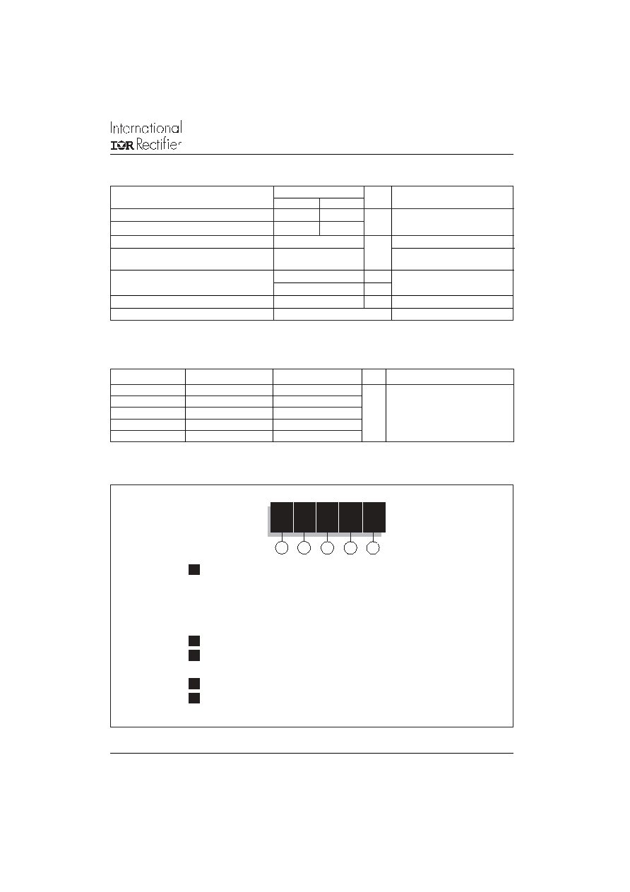
Ordering Information Table
1
2
3
4
5
Device Code
40
HF
R
160
M
1
-
40 = Standard device
41 = Not isolated lead
42 = Isolated lead with silicone sleeve
(Red = Reverse polarity)
(Blue = Normal polarity)
2
-
Standard diode
3
-
None = Stud Normal Polarity (Cathode to Stud)
R
= Stud Reverse Polarity (Anode to Stud)
4
-
Voltage code: Code x 10 = V
RRM
(See Voltage Ratings table)
5
-
None = Stud base DO-203AB (DO-5) 1/4" 28UNF-2A
M
= Stud base DO-203AB (DO-5) M6 X 1
40HF(R) Series
4
Bulletin I20201 rev. C 03/04
www.irf.com
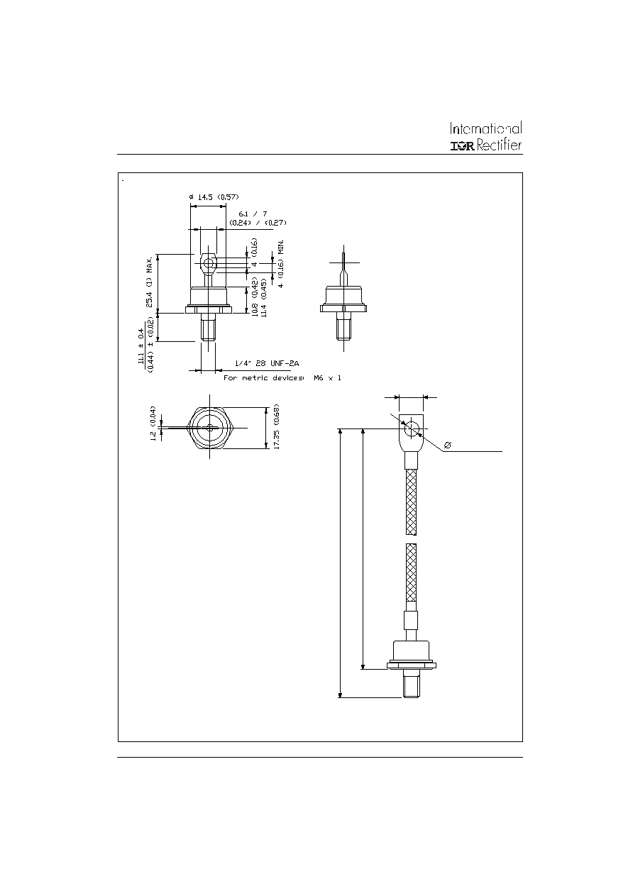
11 (0.43) MAX.
6.3 (0.25) MAX.
107 (4.21) MAX.
118.5 (4.67) MAX.
Outlines Table
41HF(R)
Case Style DO-203AB (DO-5)
All dimensions in millimeters (inches)
40HF(R)
Case Style DO-203AB (DO-5)
All dimensions in millimeters (inches)
40HF(R) Series
5
Bulletin I20201 rev. C 03/04
www.irf.com
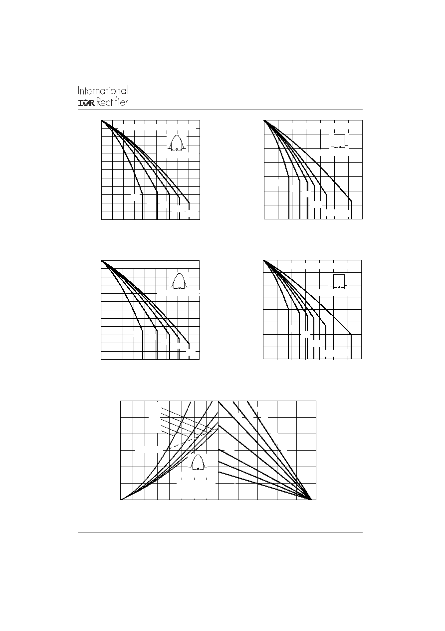
Fig. 5 - Forward Power Loss Characteristics
Fig. 3 - Current Ratings Characteristics
Fig. 4 - Current Ratings Characteristics
Fig. 1 - Current Ratings Characteristics
Fig. 2 - Current Ratings Characteristics
Average Forward Current (A)
Maximum Allowable Case Temperature (∞C)
Average Forward Current (A)
Maximum Allowable Case Temperature (∞C)
Average Forward Current (A)
Maximum Allowable Case Temperature (∞C)
Average Forward Current (A)
Maximum Allowable Case Temperature (∞C)
130
140
150
160
170
180
190
0
5 10 15 20 25 30 35 40 45
30∞
60∞
90∞
120∞
180∞
Conduction Angle
40HF(R) Series (100V to 1200V)
100
110
120
130
140
150
160
0
5 10 15 20 25 30 35 40 45
30∞
60∞
90∞
120∞
180∞
Conduction Angle
40HF(R) Series (1400V, 1600V)
120
130
140
150
160
170
180
190
0
10
20
30
40
50
60
70
DC
30∞
60∞
90∞
120∞
180∞
Conduction Period
40HF(R) Series (100V to 1200V)
80
90
100
110
120
130
140
150
160
0
10
20
30
40
50
60
70
DC
30∞
60∞
90∞
120∞
180∞
Conduction Period
40HF(R) Series (1400V, 1600V)
Average Forward Current (A)
Maximum Average Forward Power Loss (W)
Maximum Allowable Ambient Temperature (∞C)
0
40
80
120
160
200
10 K/W
RthSA = 1 K/W - Delta R
1.5 K/W
2 K/W
3 K/W
5 K/W
7 K/W
0
10
20
30
40
50
60
0
5
10 15 20 25 30 35 40
RMS Limit
Conduction Angle
180∞
120∞
90∞
60∞
30∞
40HF(R) Series
(100V to 1200V)
Tj = 190∞C