 | –≠–ª–µ–∫—Ç—Ä–æ–Ω–Ω—ã–π –∫–æ–º–ø–æ–Ω–µ–Ω—Ç: 50PFR120 | –°–∫–∞—á–∞—Ç—å:  PDF PDF  ZIP ZIP |

Features
High surge current capability
Designed for a wide range of applications
Stud cathode and stud anode version
Leaded version available/ wire version available
Low thermal resistance
UL approval pending
Typical Applications
Battery charges
Converters
Power supplies
Machine tool controls
Welding
Parameters
Units
50PF (R)...(W)
40 to 120
I
F(AV)
50
A
@ T
C
140
∞C
I
F(RMS)
78
A
I
FSM
@
50Hz
800
A
@ 60Hz
830
I
2
t
@
50Hz
3200
A
2
s
@ 60Hz
2900
V
RRM
range
400 to 1200
V
T
J
range
- 55 to 180
∞C
Major Ratings and Characteristics
50PF(R)...(W) SERIES
STANDARD RECOVERY DIODES
GEN II DO5
50 A
1
Stud Version
Bulletin I20105 rev. D 01/05
case style DO-203AB (DO-5)
50PF(R)...W
50PF(R)...
case style DO-203AB (DO-5)
www.irf.com

50PF (R)...(W) Series
2
Bulletin I20105 rev. D 01/05
www.irf.com
Voltage
V
RRM
, maximum
V
RSM
, maximum non-
I
RRM
max.
Type number
Code
repetitive peak
repetitive peak
@ T
J
= 150∞C
reverse voltage
reverse voltage
V
V
mA
40
400
500
50PF (R)...(W)
80
800
960
9
120
1200
1440
ELECTRICAL SPECIFICATIONS
Voltage Ratings
I
F(AV)
Max. average forward current
50
A
180∞ conduction, half sine wave
@ Case temperature
140
∞C
I
F(RMS)
Max. RMS forward current
78
A
I
FSM
Max. peak, one-cycle forward,
800
t = 10ms
No voltage
non-repetitive surge current
830
t = 8.3 ms
reapplied
670
t = 10ms
100% V
RRM
700
t = 8.3 ms
reapplied
Sinusoidal half wave,
I
2
t
Maximum I
2
t for fusing
3200
t = 10ms
No voltage
Initial T
J
= 150∞C
2900
t = 8.3ms
reapplied
2260
t = 10ms
100% V
RRM
2050
t = 8.3ms
reapplied
I
2
t
Maximum I
2
t for fusing
32000
A
2
s
t = 0.1 to 10ms, no voltage reapplied
V
F(TO)
Low level value of threshold
voltage
r
f
Low level value of forward
slope resistance
V
FM
Max. forward voltage drop
1.40
V
I
pk
= 125A, T
J
= 25∞C, t
p
= 400µs rectangular wave
Parameter
Units Conditions
4.30
m
(16.7% x x I
F(AV)
< I < x I
F(AV)
), T
J
= T
J
max.
0.77
V
(16.7% x x I
F(AV)
< I < x I
F(AV)
), T
J
= T
J
max.
A
2
s
A
Forward Conduction
50PF(R)...(W)
40 to 120

50PF (R)...(W) Series
3
Bulletin I20105 rev. D 01/05
www.irf.com
Parameter
Units
Conditions
50PF (R)...(W)
40 to 120
T
J
Max. junction operating temperature range
-55 to 180
T
stg
Max. storage temperature range
-55 to 180
R
thJC
Max. thermal resistance, junction to case
0.51
DC operation
R
thCS
Max. thermal resistance, case
Mounting surface, smooth, flat and
to heatsink
greased
T
Allowable mounting torque 3.4
+0-10%
N m Tighting on nut (1)
30
lbf
∑
in
Not lubricated threads
2.3
+0-10%
N m
Tighting on hexagon (2)
20
lbf
∑
in
Lubricated threads
wt
Approximate weight
15.8 (0.56)
g (oz)
Case style
DO-203AB (DO5)
See Outline Table
∞C
0.25
K/W
Thermal and Mechanical Specifications
180∞
0.11
0.10
T
J
= T
J
max.
120∞
0.16
0.16
90∞
0.20
0.22
60∞
0.29
0.31
30∞
0.49
0.50
Conduction angle
Sinusoidal conduction
Rectangular conduction Units
Conditions
K/W
R
thJC
Conduction
(The following table shows the increment of thermal resistence R
thJC
when devices operate at different conduction angles than DC)
(1) As general recommendation we suggest to tight on Hexagon and not on nut
(2) Torque must be appliable only to Hexagon and not to plastic structure
110
120
130
140
150
160
170
180
0
10
20
30
40
50
60
30∞
60∞
90∞
120∞
180∞
Conduction Angle
50PF(R) Serie
RthJC = 0.51 K/W
120
130
140
150
160
170
180
0
10 20 30 40 50 60 70 80
DC
30∞
60∞
90∞
120∞
180∞
Conduction Period
50PF(R) Series
RthJC (DC) = 0.51 K/W
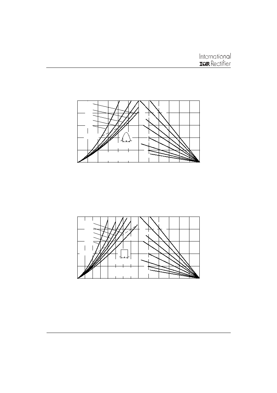
Average Forward Current (A)
Fig. 1 - Current Ratings Characteristics
Average Forward Current (A)
Fig. 2 - Current Ratings Characteristics
Maximum Allowable Case Temperature (∞C)
Maximum Allowable Case Temperature (∞C)
50PF (R)...(W) Series
4
Bulletin I20105 rev. D 01/05
www.irf.com
Average Forward Current (A)
Fig. 3 - Forward Power Loss Characteristics
Maximum Allowable Forward Power Loss (W)
Average Forward Current (A)
Fig. 4 - Forward Power Loss Characteristics
Maximum Allowable Forward Power Loss (W)
0
30
60
90
120 150 180
1 K/W
1.5 K/W
2 K/W
0.7 K/W
3 K/W
5 K/W
7 K/W
10 K/W
0
20
40
60
80
100
0
10
20
30
40
50
60
RMS Limit
Conduction Angle
180∞
120∞
90∞
60∞
30∞
50PF(R) Series
Tj = 180∞C
0
30
60
90
120 150 180
1 K/W
1.5 K/W
2 K/W
0.7 K/W
3 K/W
5 K/W
7 K/W
10 K/W
0
20
40
60
80
100
0
20
40
60
80
RMS Limit
Conduction Period
50PF(R) Series
Tj = 180∞C
180∞
120∞
90∞
60∞
30∞
DC
Maximum Allowable Ambient Temperature (∞C)
Maximum Allowable Ambient Temperature (∞C)

50PF (R)...(W) Series
5
Bulletin I20105 rev. D 01/05
www.irf.com
1
10
100
1000
0
1
2
3
4
Tj = 25∞C
50PF(R) Series
Tj = 180∞C
0.01
0.1
1
0.0001 0.001 0.01
0.1
1
10
Steady State Value
RthJC = 0.51 K/W
(DC Operation)
50PF(R) Series
Instantaneous Forward Voltage (V)
Fig. 7 - Forward Voltage Drop Characteristics
Instantaneous Forward Current (A)
Square Wave Pulse Duration (s)
Fig. 8 - Thermal Impedance Z
thJC
Characteristics
Transient Thermal Impedance Z
thJC
(K/W)
200
300
400
500
600
700
800
1
10
100
At Any Rated Load Condition And With
Rated Vrrm Applied Following Surge.
50PF(R) Series
Initial Tj = 150∞C
@ 60 Hz 0.0083 s
@ 50 Hz 0.0100 s
100
200
300
400
500
600
700
800
900
0.01
0.1
1
Maximum Non Repetitive Surge Current
Versus Pulse Train Duration.
50PF(R) Series
Initial Tj = 150∞C
No Voltage Reapplied
Rated Vrrm Reapplied
Number Of Equal Amplitude Half Cycle Current Pulses (N)
Fig. 5 - Maximum Non -Repetitive Surge Current
Peak Haf Sine Wave Forward Current (A)
Pulse Train Duration (s)
Fig. 6 - Maximum Non -Repetitive Surge Current
Peak Haf Sine Wave Forward Current (A)