 | –≠–ª–µ–∫—Ç—Ä–æ–Ω–Ω—ã–π –∫–æ–º–ø–æ–Ω–µ–Ω—Ç: 70MT140PB | –°–∫–∞—á–∞—Ç—å:  PDF PDF  ZIP ZIP |
45 A
75 A
100 A
THREE PHASE BRIDGE
Bulletin I27145 rev. B 06/02
1
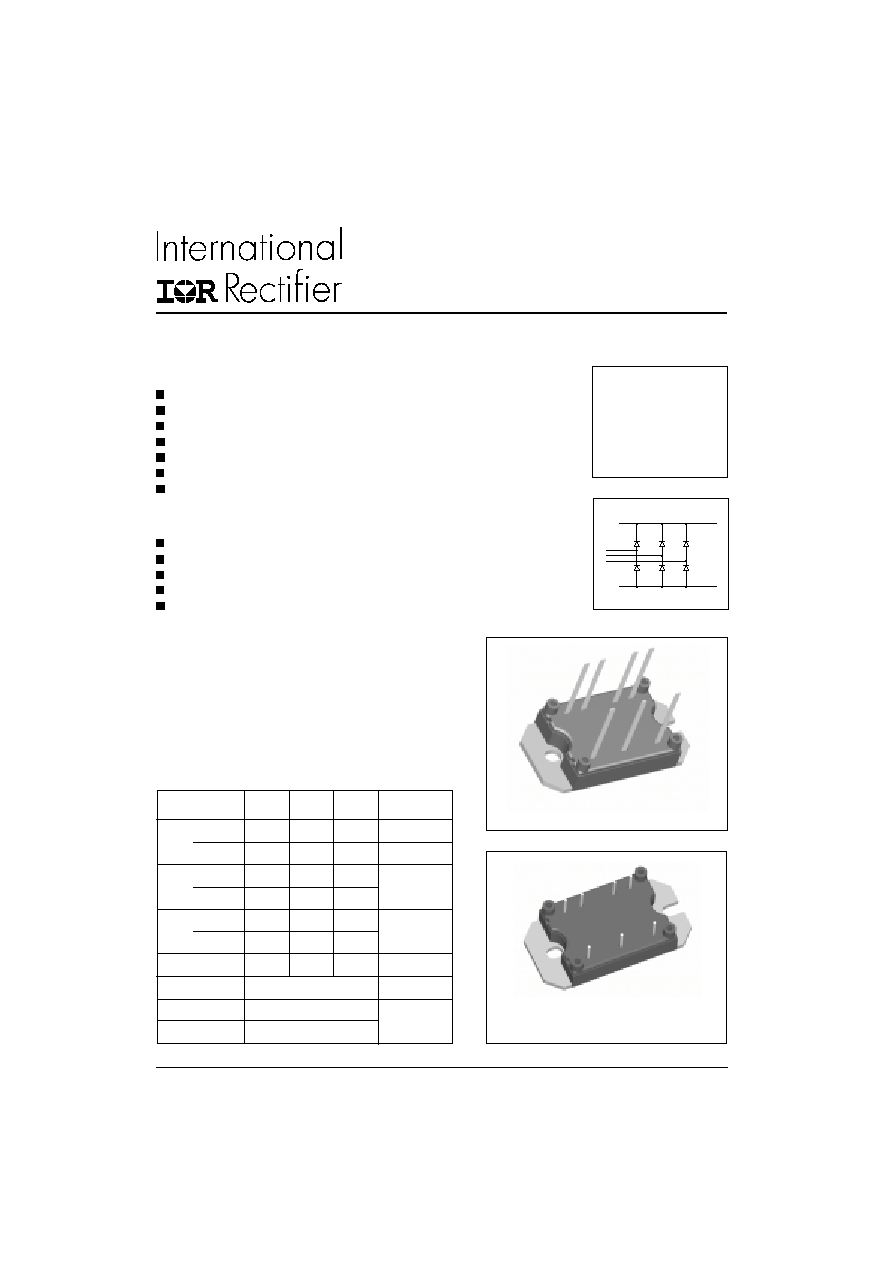
MTP 3-Phase
Rectifier Series
Power Module
I
O
45
75
100
A
@ T
C
100
80
80
∞C
I
FSM
@ 50Hz
270
380
450
A
@ 60Hz
280
398
470
I
2
t
@ 50Hz
365
724
1013
A
2
s
@ 60Hz
325
660
920
I
2
t
3650
7240
10130
A
2
s
V
RRM
1400 & 1600
V
T
STG
range
- 40 to 125
∞C
T
J
range
- 40 to 150
Major Ratings and Characteristics
Features
Low V
F
Low profile package
Direct Mounting to heatsink
Flat-Pin/ Round-Pin versions with PCB solderable terminals
Low junction-to-case Thermal Resistance
3500 V
RMS
insulation voltage
UL approval pending
Parameters
40MT 70MT 100MT
Units
www.irf.com
MT...PB
Applications: Power conversion machines
Welding
UPS
SMPS
Motor Drives
General Purpose & Heavy Duty Applications
Description
A range of extremely compact three-phase rectifier bridges
offering efficient and reliable operation.
The low profile package has been specifically conceived to
maximize space saving and optimize the electrical layout of
the application specific Power Supplies.
MT...PA
MTP 3-Phase Rectifier Series
2
Bulletin I27145 rev. B 06/02
www.irf.com
I
O
Maximum DC output current
45
75
100
A
120∞ Rect conduction angle
@ Case temperature
100
80
80
∞C
I
FSM
Maximum peak, one-cycle
270
380
450
A
t = 10ms
No voltage
forward, non-repetitive
280
398
470
t = 8.3ms
reapplied
on state surge current
225
320
380
t = 10ms
100% V
RRM
240
335
400
t = 8.3ms
reapplied
Initial
I
2
t
Maximum I
2
t for fusing
365
724
1013
A
2
s
t = 10ms
No voltage
T
J
= T
J
max.
325
660
920
t = 8.3ms
reapplied
253
512
600
t = 10ms
100% V
RRM
240
467
665
t = 8.3ms
reapplied
I
2
t
Maximum I
2
t for fusing
3650
7240
10130
A
2
s
t = 0.1 to 10ms, no voltage reapplied
V
F(TO)
Value of threshold voltage
0.78
0.82
0.75
V
@ T
J
max.
r
t
Slope resistance
14.8
9.5
8.1
m
V
FM
Maximum forward voltage drop
1.45
1.45
1.51
V
T
J
= 25∞C
I
pk
= 40A I
pk
= 70A I
pk
= 100A
t
p
= 400µs single junction
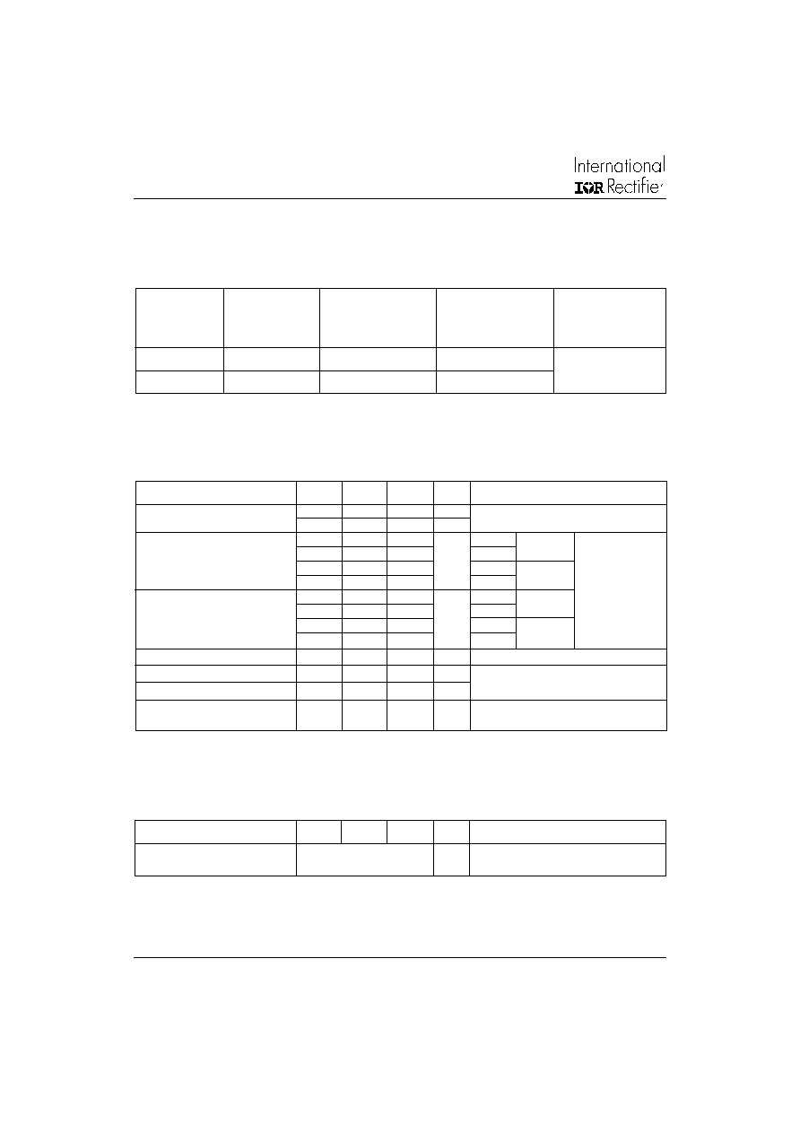
Forward Conduction
V
INS
RMS insulation voltage
3500
V
T
J
= 25
o
C all terminal shorted
f = 50Hz, t = 1s
Insulation Table
ELECTRICAL SPECIFICATIONS
Voltage Ratings
Parameter
40MT
70MT
100MT
Units Conditions
Voltage
V
RRM
, maximum
V
RSM
, maximum
I
RRM
max.
Type number
Code
repetitive peak
non-repetitive peak
@ T
J
= 150∞C
reverse voltage
reverse voltage
V
V
V
mA
40-70-100MT140P
140
1400
1500
5
40-70-100MT160P
160
1600
1700
Parameter
40MT
70MT
100MT
Units Conditions
MTP 3-Phase Rectifier Series
3
Bulletin I27145 rev. B 06/02
www.irf.com
Clearance (external shortest distance in air between terminals which
are not internally short circuited together)
Creepage distance (shortest distance along external surface of the
insulating material between terminals which are not internally short
circuited together)
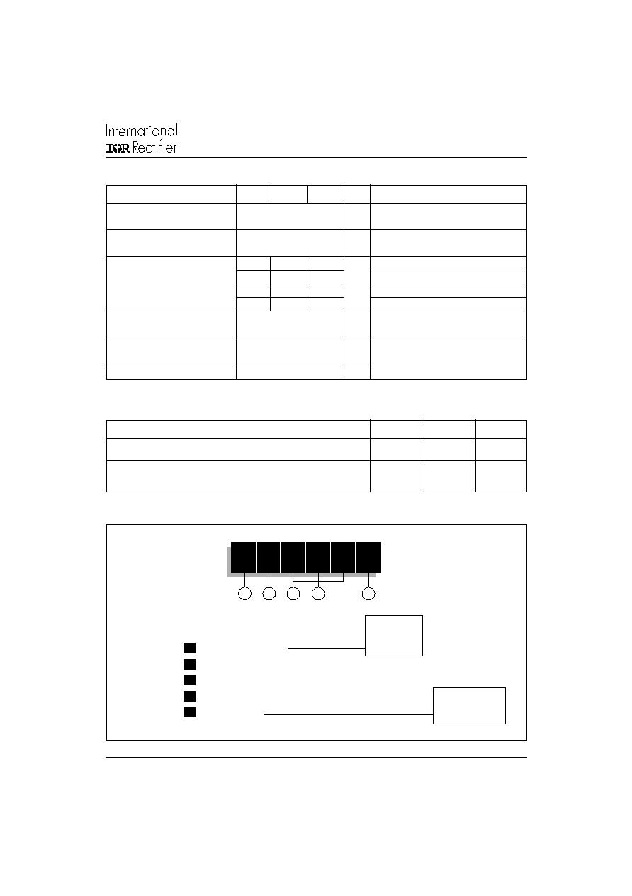
Thermal and Mechanical Specifications
T
J
Maximum junction operating
- 40 to 150
∞C
temperature range
T
stg
Maximum storage temperature
-40 to 125
∞C
range
R
thJC
Maximum thermal resistance,
0.27
0.23
0.19
K/W
DC operation per module
junction to case
1.6
1.38
1.14
DC operation per junction
0.38
0.29
0.22
120∞ Rect condunction angle per module
2.25
1.76
1.29
120∞ Rect condunction angle per junction
R
thCS
Maximum thermal resistance,
0.1
K/W
case to heatsink
T
Mounting torque ± 10%
4
Nm
to heatsink
wt
Approximate weight
65
g
A mounting compound is recommended and the
torque should be rechecked after a period of 3
hours to allow for the spread of the compound.
Lubricated threads.
Per module.
Mounting surface smooth, flat and greased.
Heatsink compound thermal conductivity = 0.42W/mK
1
2
3
1
- Current rating code
2
- Circuit configuration code: 0 = 3-Phase Rectifier Bridge
3
- Essential part number
4
- Voltage code: code x 10 = V
RRM
(See Voltage Ratings table)
5
- Pinout code:
4
Device Code
Ordering Information Table
10
0
MT 160
P
B
5
A = Flat pins
B = Round pins
Parameter
40MT
70MT
100MT
Units Conditions
4
= 45A
7
= 75A
10 = 100A
Clearance and Creepage Distances
Parameter
MT...PA
MT...PB
Units
10.9
12.3
mm
10.9
12.3
mm
MTP 3-Phase Rectifier Series
4
Bulletin I27145 rev. B 06/02
www.irf.com
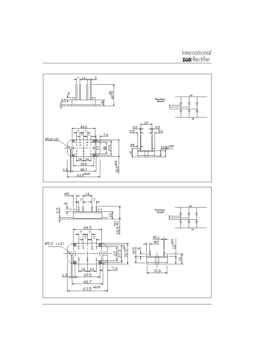
Outline Table
MT...PA
(Flat pin)
Dimensions in millimeters
MT...PB
(Round pin)
Dimensions in millimeters
MTP 3-Phase Rectifier Series
5
Bulletin I27145 rev. B 06/02
www.irf.com
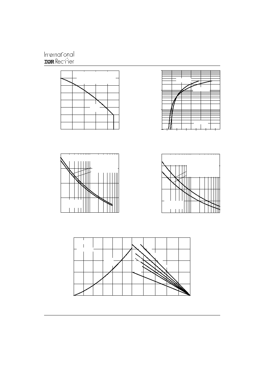
Fig. 1 - Current Rating Characteristics
Fig. 3 - Maximum Non-Repetitive Surge Current
Fig. 4 - Maximum Non-Repetitive Surge Current
Fig. 5 - Current Rating Nomogram (1 Module Per Heatsink)
Total Output Current (A)
Maximum Allowable Case Temperature (∞C)
Instantaneous On-state Current (A)
Number Of Equal Amplitude Half Cycle Current Pulses (N)
Peak Half Sine Wave On-state Current (A)
Instantaneous On-state Voltage (V)
Pulse Train Duration(s)
Peak Half Sine Wave On-state Current (A)
Maximum Allowable Ambient Temperature (∞C)
Total Output Current (A)
Maximum Total Power Loss (W)
0
30
60
90
120
150
RthSA = 0.1 K/W - Delta R
0.3 K/W
0.4 K/W
0.5 K/W
1 K/W
0.2 K/W
Fig. 2 - On-state Voltage Drop Characteristics
1
10
100
1000
0
1
2
3
4
5
6
Tj = 150∞C
Tj = 25∞C
40MT...P
50
100
150
200
250
1
10
100
At Any Rated Load Condition And With
Rated Vrrm Applied Following Surge.
Initial Tj = 150∞C
@ 60 Hz 0.0083 s
@ 50 Hz 0.0100 s
40MT...P
Per Junction
50
100
150
200
250
300
0.01
0.1
1
Maximum Non Repetitive Surge Current
Versus Pulse Train Duration. Control
Of Conduction May Not Be Maintained.
Initial T j = 150∞C
No Voltage Reapplied
Rated V rrm Reapplied
40MT...P
Per Junction
0
50
100
150
200
250
0
10
20
30
40
50
60
120∞
(Rect)
Tj = 150∞C
40MT...P
80
90
100
110
120
130
140
150
160
0
10
20
30
40
50
120∞
(Rect)
40MT...P
R (DC) = 0.27 K/W
Per Module
thJC