 | –≠–ª–µ–∫—Ç—Ä–æ–Ω–Ω—ã–π –∫–æ–º–ø–æ–Ω–µ–Ω—Ç: 70TPS12 | –°–∫–∞—á–∞—Ç—å:  PDF PDF  ZIP ZIP |
Major Ratings and Characteristics
I
T(AV)
Sinusoidal
70
A
waveform
I
RMS
(*)
75
A
V
RRM
/ V
DRM
1200, 1600
V
I
TSM
1400
A
V
T
@ 100 A, T
J
= 25∞C
1.4
V
dv/dt
500
V/µs
di/dt
150
A/µs
T
J
- 40 to 125
∞C
Characteristics
70TPS..
Units
Super-247
Description/ Features
The 70TPS... SAFE
IR
series of silicon controlled
rectifiers are specifically designed for high and
medium power switching and phase control appli-
cations.
Typical applications are in input rectification (soft
start) or AC-Switches or high current crow-bar as
well as others phase-control circuits.
These products are designed to be used with
International Rectifier input diodes, switches and
output rectifiers which are available in identical
package outlines.
Package Outline
Range
PHASE CONTROL SCR
1
Bulletin I2164 rev. A 10/04
SAFE
IR
Series
70TPS..
V
T
< 1.4V @ 100A
I
TSM
= 1400A
V
RRM
= 1200, 1600V
www.irf.com
(*) Lead current limitation

2
70TPS.. SAFE
IR
Series
Bulletin I2164 Rev. A 10/04
www.irf.com
I
T(AV)
Max. Average On-state Current
70
A
@ T
C
= 82∞ C, 180∞ conduction half sine wave
I
T(RMS)
Max. Continuous RMS
75
Lead current limitation
On-state Current As AC switch
I
TSM
Max. Peak One Cycle Non-Repetitive
1200
A
10ms Sine pulse, rated V
RRM
applied
Initial
Surge Current
1400
10ms Sine pulse, no voltage reapplied
T
J
= T
J
max.
I
2
t
Max. I
2
t for Fusing
7200
A
2
s
10ms Sine pulse, rated V
RRM
applied
10200
10ms Sine pulse, no voltage reapplied
I
2
t
Max. I
2
t for Fusing
102000
A
2
s
t = 0.1 to 10ms, no voltage reapplied
V
T(TO)
1
Low Level Value of Threshold
0.916
V
T
J
= 125∞C
Voltage
V
T(TO)
2
High Level Value of Threshold
1.21
Voltage
r
t1
Low Level Value of On-state
4.138
m
Slope Resistance
r
t2
High Level Value of On-state
3.43
Slope Resistance
V
TM
Max. Peak On-state Voltage
1.4
V
@ 100A, T
J
= 25∞C
di/dt
Max. Rate of Rise of Turned-on Current
150
A/µs
T
J
= 25∞C
I
H
Max. Holding Current
200
mA
T
J
= 25∞C
I
L
Max. Latching Current
400
I
RRM
/
Max. Reverse and Direct
1.0
mA
T
J
= 25∞C
I
DRM
Leakage Current
15
T
J
= 125∞C
dv/dt
Max. Rate of Rise
500
V/µs
T
J
= 125∞C
Voltage Ratings
Part Number
Absolute Maximum Ratings
Parameters
70TPS.. Units
Conditions
V
R
= rated V
RRM
/ V
DRM
V
RRM
/ V
DRM
, max. repetitive
V
RSM
, maximum non repetitive
I
RRM
/ I
DRM
peak and off-state voltage
peak reverse voltage
125∞C
V
V
mA
70TPS12
1200
1300
15
70TPS16
1600
1700
3
70TPS.. SAFE
IR
Series
Bulletin I2164 Rev. A 10/04
www.irf.com
P
GM
Max. peak Gate Power
10
W
t = 30µs
P
G(AV)
Max. average Gate Power
2.5
I
GM
Max. peak Gate Current
2.5
A
- V
GM
Max. peak negative Gate Voltage
10
V
V
GT
Max. required DC Gate Voltage
4.0
T
J
= - 40∞C
Anode supply = 6V
to trigger
1.5
T
J
= 25∞C
resistive load
1.1
T
J
= 125∞C
I
GT
Max. required DC Gate Current
270
mA
T
J
= - 40∞C
to trigger
100
T
J
= 25∞C
80
T
J
= 125∞C
V
GD
Max. DC Gate Voltage not to trigger
0.25
V
T
J
= 125∞C, V
DRM
= rated value
I
GD
Max. DC Gate Current not to trigger
6
mA
Parameters
70TPS.. Units
Conditions
Triggering
Thermal-Mechanical Specifications
T
J
Max. Junction Temperature Range - 40 to 125
∞C
T
stg
Max. Storage Temperature Range
- 40 to 150
R
thJC
Max. Thermal Resistance Junction
0.27
∞C/W
DC operation
to Case
R
thJA
Max. Thermal Resistance Junction
40
to Ambient
R
thCS
Max. Thermal Resistance Case
0.2
Mounting surface, smooth and greased
to Heatsink
wt
Approximate Weight
6 (0.21)
g (oz.)
T
Mounting Torque
Min.
6 (5)
Kg-cm
Max.
12 (10)
(lbf-in)
Case Style
Super-247
Parameters
70TPS.. Units
Conditions
Sine half wave conduction
Rect. wave conduction
Device
Units
180
o
120
o
90
o
60
o
30
o
180
o
120
o
90
o
60
o
30
o
70TPS
0.078
0.092
0.117
0.172
0.302
0.053
0.092
0.125
0.180
0.306
∞C/W
R Conduction (per Junction)
(The following table shows the increment of thermal resistance R
thJC
when devices operate at different conduction angles than DC)
4
70TPS.. SAFE
IR
Series
Bulletin I2164 Rev. A 10/04
www.irf.com
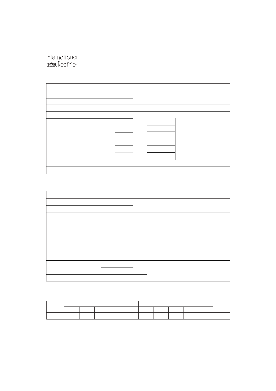
Fig. 1 - Current Rating Characteristics
Fig. 2 - Current Rating Characteristics
Fig. 3 - On-state Power Loss Characteristics
Fig. 4 - On-state Power Loss Characteristics
Fig. 5 - Maximum Non-Repetitive Surge Current
Fig. 6 - Maximum Non-Repetitive Surge Current
Average On-state Current (A)
Maximum Allowable Case temperature (∞C)
Average On-state Current (A)
Maximum Allowable Case temperature (∞C)
Average On-state Current (A)
Maximum Average On-state Power Loss (W)
Average On-state Current (A)
Maximum Average On-state Power Loss (W)
Number Of Equal Amplitude Half Cycle Current Pulses (N)
Peak Half Sine Wave On-state Current (A)
Pulse Train Duration (s)
Peak Half Sine Wave On-state Current (A)
500
600
700
800
900
1000
1100
1200
1300
1
10
100
70TPS.. Series
At Any Rated Load Condition And With
Rated Vrrm Applied Following Surge.
Initial Tj = 125∞C
@ 60 Hz 0.0083 s
@ 50 Hz 0.0100 s
500
600
700
800
900
1000
1100
1200
1300
1400
1500
0.01
0.1
1
Maximum Non Repetitive Surge Current
Versus Pulse Train Duration. Control
Of Conduction May Not Be Maintained.
Initial Tj = 125∞C
No Voltage Reapplied
Rated Vrrm Reapplied
70TPS.. Series
70
80
90
100
110
120
130
0
10 20 30 40 50 60 70 80
30∞
60∞
90∞
120∞
180∞
Conduction Angle
70TPS.. Series
RthJC (DC) = 0.27 ∞C/W
0
20
40
60
80
100
120
140
0
10
20
30
40
50
60
70
RMS Limit
Conduction Angle
180∞
120∞
90∞
60∞
30∞
70TPS.. Series
Tj = 125∞C
60
70
80
90
100
110
120
130
0 10 20 30 40 50 60 70 80 90
DC
30∞ 60∞
90∞
120∞
180∞
Conduction Period
70TPS.. Series
RthJC (DC) = 0.27 ∞C/W
0
30
60
90
120
150
0
15
30
45
60
75
RMS Limit
Conduction Period
70TPS.. Series
Tj = 125∞C
180∞
120∞
90∞
60∞
30∞
DC
5
70TPS.. SAFE
IR
Series
Bulletin I2164 Rev. A 10/04
www.irf.com
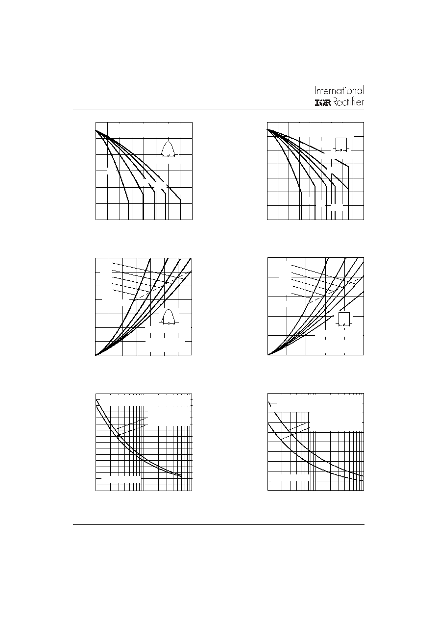
Fig. 7 - On-state Voltage Drop Characteristics
Fig. 8 - GateCharacteristics
Fig. 9 - Thermal Impedance Z
thJC
Characteristics
Instantaneous On-state Voltage (A)
Instantaneous On-state Current (A)
Instantaneous Gate Current (A)
Instantaneous Gate Voltage (V)
Square Wave Pulse Duration (s)
Transient Thermal Impedance Z
thJC
(∞C/W)
0.01
0.1
1
0.0001
0.001
0.01
0.1
1
10
Steady State Value
(DC Operation)
Single Pulse
D = 0.50
D = 0.33
D = 0.25
D = 0.17
D = 0.08
70TPS.. Series
1
10
100
1000
0.5
1
1.5
2
2.5
3
3.5
70TPS.. Series
Tj = 25∞C
Tj = 125∞C
0.1
1
10
100
0.001
0.01
0.1
1
10
100
1000
(b)
(a)
Rectangular gate pulse
(4) (3) (2) (1)
(1) PGM = 100 W, tp = 500 µs
(2) PGM = 50 W, tp = 1 ms
(3) PGM = 20 W, tp = 25 ms
(4) PGM = 10 W, tp = 5 ms
TJ = -40
∞
C
TJ = 25
∞
C
TJ = 125
∞
C
a)Recommended load line for
b)Recommended load line for
VGD
IGD
Frequency Limited by PG(AV)
rated di/dt: 20 V, 30 ohms
tr = 0.5 µs, tp >= 6 µs
<= 30% rated di/dt: 20 V, 65 ohms
tr = 1 µs, tp >= 6 µs
70TPS.. Series
6
70TPS.. SAFE
IR
Series
Bulletin I2164 Rev. A 10/04
www.irf.com
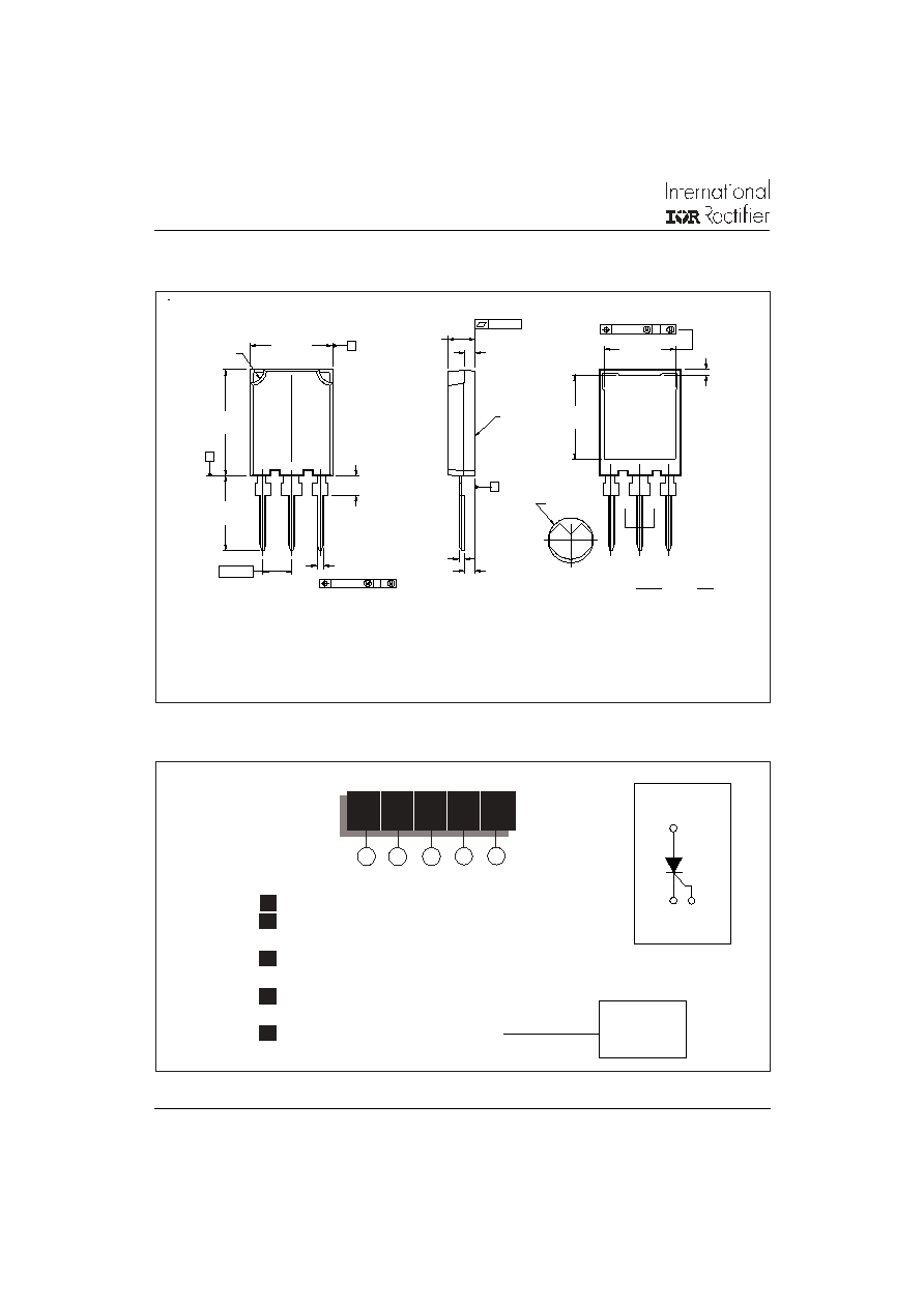
Outline Table
Dimensions in millimeters and inches
Ordering Information Table
70
T
P
S
16
Device Code
1
5
2
4
3
1
-
Current Rating
2
-
Circuit Configuration:
T = Thyristor
3
-
Package:
P = Super-247
4
-
Type of Silicon:
S = Standard Recovery Rectifier
5
-
Voltage code: Code x 100 = V
RRM
12 = 1200V
16 = 1600V
(G) 3
2
(A)
1 (K)
B
ÿ 1.60 [.063]
1
2
0.25 [.010]
B A
3
0.13 [.005]
E
E
4
0.25 [.010]
B A
4
A
2X R
MAX.
SECTION E-E
2X
3X
1. DIMENSIONING AND TOLERANCING PER ASME Y14.5M-1994.
2. DIMENSIONS ARE SHOWN IN MILLIMETERS [INCHES]
3. CONTROLLING DIMENSION: MILLIMETER
NOTES:
4. OUTLINE CONFORMS TO JEDEC OUTLINE TO-274AA
3 - SOURCE
2 - DRAIN
1 - GATE
4 - DRAIN
3 - EMITTER
4 - COLLECTOR
1 - GATE
2 - COLLECTOR
LEAD ASSIGNMENTS
MOSFET
IGBT
C
5.45 [.215]
2.35 [.092]
1.65 [.065]
4.25 [.167]
3.85 [.152]
16.10 [.632]
15.10 [.595]
3X
20.80 [.818]
19.80 [.780]
14.80 [.582]
13.80 [.544]
16.10 [.633]
15.50 [.611]
1.30 [.051]
1.10 [.044]
1.30 [.051]
0.70 [.028]
2.15 [.084]
1.45 [.058]
5.50 [.216]
4.50 [.178]
13.90 [.547]
13.30 [.524]
NOTE:parts are designed for clip mounting to heatsinks; mounting requirements and methods are
discussed in AN-997
7
70TPS.. SAFE
IR
Series
Bulletin I2164 Rev. A 10/04
www.irf.com
IR WORLD HEADQUARTERS: 233 Kansas St., El Segundo, California 90245, USA Tel: (310) 252-7105
TAC Fax: (310) 252-7309
Visit us at www.irf.com for sales contact information. 10/04
Data and specifications subject to change without notice.
This product has been designed for Industrial Level.
Qualification Standards can be found on IR's Web site.