85HF-P1
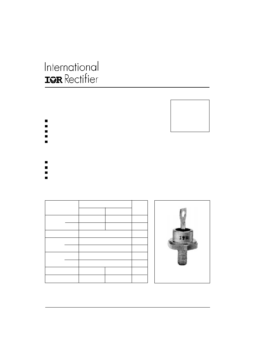
85HF(R) SERIES
STANDARD RECOVERY DIODES
85 A
1
Stud Version
Bulletin I20203 rev. A 09/98
www.irf.com
Features
High surge current capability
Designed for a wide range of applications
Stud cathode and stud anode version
Leaded version available
Types up to 1600V V
RRM
Typical Applications
Battery charges
Converters
Power supplies
Machine tool controls
Parameters
Units
85HF(R)
10 to 120
140 to 160
I
F(AV)
85
85
A
@ T
C
140
110
�C
I
F(RMS)
133
A
I
FSM
@
50Hz
1700
A
@ 60Hz
1800
A
I
2
t
@
50Hz
14500
A
2
s
@ 60Hz
13500
A
2
s
V
RRM
range
100 to 1200
1400 to 1600
V
T
J
range
- 65 to 180
- 65 to 150
�C
Major Ratings and Characteristics
case style
DO-203AB (DO-5)
85HF(R) Series
2
Bulletin I20203 rev. A 09/98
www.irf.com
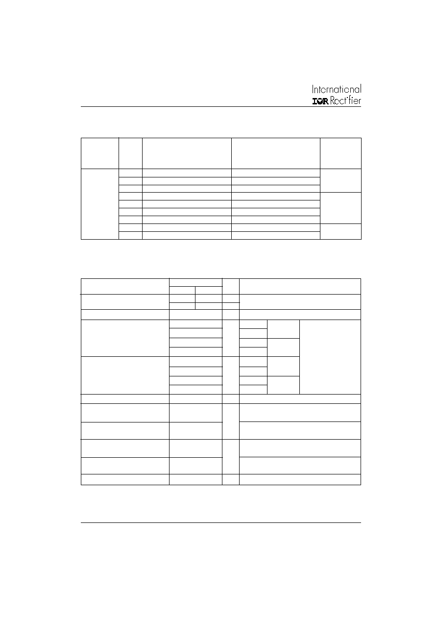
Voltage
V
RRM
, maximum repetitive
V
RSM
, maximum non-repetitive
I
RRM
max.
Type number
Code
peak reverse voltage
peak reverse voltage
@ T
J
= T
J
max.
V
V
mA
10
100
200
15
20
200
300
40
400
500
60
600
720
9
85HF(R)
80
800
960
100
1000
1200
120
1200
1440
140
1400
1650
4.5
160
1600
1900
ELECTRICAL SPECIFICATIONS
Voltage Ratings
I
F(AV)
Max. average forward current
85
85
A
180� conduction, half sine wave
@ Case temperature
140
110
�C
I
F(RMS)
Max. RMS forward current
133
A
I
FSM
Max. peak, one-cycle forward,
1700
t = 10ms
No voltage
non-repetitive surge current
1800
t = 8.3ms
reapplied
1450
t = 10ms
100% V
RRM
1500
t = 8.3ms
reapplied
Sinusoidal half wave,
I
2
t
Maximum I
2
t for fusing
14500
t = 10ms
No voltage
Initial T
J
= T
J
max.
13500
t = 8.3ms
reapplied
10500
t = 10ms
100% V
RRM
9400
t = 8.3ms
reapplied
I
2
t
Maximum I
2
t for fusing
16000
A
2
s
t = 0.1 to 10ms, no voltage reapplied
V
F(TO)1
Low level value of threshold
voltage
V
F(TO)2
High level value of threshold
voltage
r
f
1
Low level value of forward
slope resistance
r
f
2
High level value of forward
slope resistance
V
FM
Max. forward voltage drop
1.20
V
I
pk
= 267A, T
J
= 25�C, t
p
= 400�s rectangular wave
85HF(R)
10 to 120 140 to 160
Parameter
Units Conditions
1.25
(I >
x I
F(AV)
), T
J
= T
J
max.
1.62
(16.7% x
x I
F(AV)
< I <
x I
F(AV)
), T
J
= T
J
max.
m
0.80
(I >
x I
F(AV)
), T
J
= T
J
max.
0.68
(16.7% x
x I
F(AV)
< I <
x I
F(AV)
), T
J
= T
J
max.
V
A
2
s
A
Forward Conduction
85HF(R) Series
3
Bulletin I20203 rev. A 09/98
www.irf.com
Parameter
Units
Conditions
85HF(R)
10 to 120
140 to 160
T
J
Max. junction operating temperature range
-65 to 180
-65 to 150
T
stg
Max. storage temperature range
-65 to 180
-65 to 150
R
thJC
Max. thermal resistance, junction to case
0.35
DC operation
R
thCS
Max. thermal resistance, case
Mounting surface, smooth, flat and
to heatsink
greased
Maximum shock
1500g
see note (1)
Maximum constant vibration
20g
50Hz
see note (1)
Maximum constant acceleration
5000g
Stud outwards
see note (1)
T
Max. allowed mounting torque �10%
2.3 - 3.4
Nm
Not lubricated threads
20 - 30
lbf
�
in
wt
Approximate weight
17 (0.6)
g (oz)
Case style
DO-203AB (DO5)
See Outline Table
�C
0.25
K/W
Thermal and Mechanical Specifications
180�
0.10
0.08
T
J
= T
J
max.
120�
0.11
0.11
90�
0.13
0.13
60�
0.17
0.17
30�
0.26
0.26
Conduction angle
Sinusoidal conduction
Rectangular conduction Units
Conditions
K/W
R
thJC
Conduction
(The following table shows the increment of thermal resistence R
thJC
when devices operate at different conduction angles than DC)
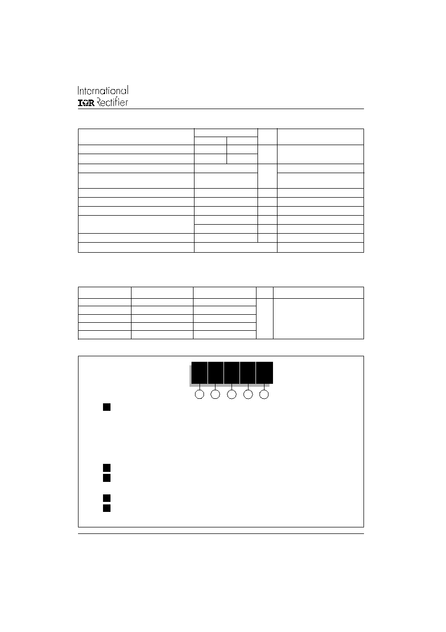
Ordering Information Table
1
2
3
4
5
Device Code
85
HF
R
160
M
1
-
85 = Standard device
86 = Not isolated lead
87 = Isolated lead with silicone sleeve
(Red = Reverse polarity)
(Blue = Normal polarity)
88 = Type for rotating application
2
-
Standard diode
3
-
None = Stud Normal Polarity (Cathode to Stud)
R
= Stud Reverse Polarity (Anode to Stud)
4
-
Voltage code: Code x 10 = V
RRM
(See Voltage Ratings table)
5
-
None = Stud base DO-203AB (DO-5) 1/4" 28UNF-2A
M
= Stud base DO-203AB (DO-5) M6 X 1 - (Not available for 88HF)
(1) Available only for 88HF
85HF(R) Series
4
Bulletin I20203 rev. A 09/98
www.irf.com
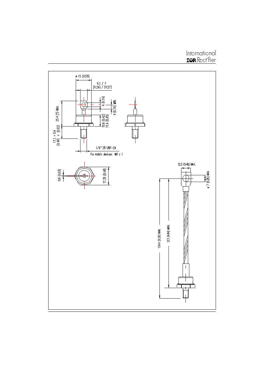
Outlines Table
86HF(R)
Case Style DO-203AB (DO-5)
All dimensions in millimeters (inches)
85HF(R)
Case Style DO-203AB (DO-5)
All dimensions in millimeters (inches)

85HF(R) Series
5
Bulletin I20203 rev. A 09/98
www.irf.com
Outlines Table
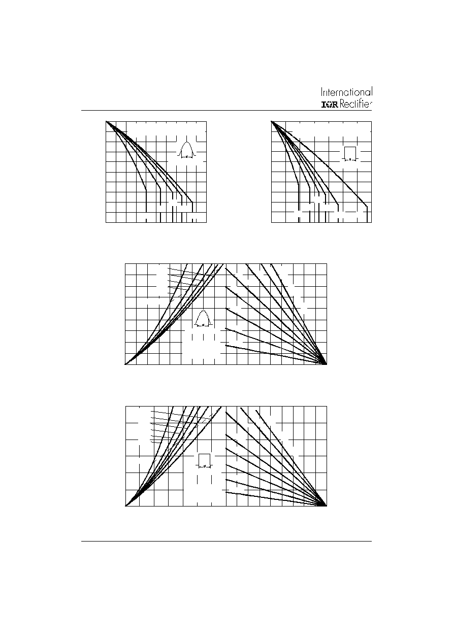
Fig. 1 - Current Ratings Characteristics
Fig. 2 - Current Ratings Characteristics
130
140
150
160
170
180
0
10 20 30 40 50 60 70 80 90 100
30�
60�
90�
120�
180�
M
a
x
i
m
u
m
A
l
l
o
w
a
bl
e C
a
s
e
T
e
m
p
e
r
a
t
u
r
e (
�C
)
Conduction Angle
Average Forward Current (A)
85HF(R) Series (100V to 1200V)
R (DC) = 0.35 K/W
thJC
130
140
150
160
170
180
0
20
40
60
80
100
120
140
DC
30�
60�
90�
120�
180�
M
a
x
i
m
u
m
A
l
l
o
w
a
b
l
e C
a
s
e
T
e
m
p
er
at
ur
e (
�C)
Conduction Period
Average Forward Current (A)
85HF(R) Series (100V to 1200V)
R (DC) = 0.35 K/W
thJC
88HF(R)
Case Style DO-203AB (DO-5)
All dimensions in millimeters (inches)
85HF(R) Series
6
Bulletin I20203 rev. A 09/98
www.irf.com
Fig. 5 - Forward Power Loss Characteristics
Fig. 3 - Current Ratings Characteristics
Fig. 4 - Current Ratings Characteristics
100
110
120
130
140
150
0
10 20 30 40 50 60 70 80 90 100
30�
60�
90�
120�
180�
M
a
x
i
m
u
m
A
l
l
o
w
abl
e C
a
s
e
T
e
m
p
e
r
a
t
ur
e
(
�C)
Conduction Angle
Average Forward Current (A)
85HF(R) Series (1400V to 1600V)
R (DC) = 0.35 K/W
thJC
100
110
120
130
140
150
0
20
40
60
80
100
120
140
DC
30�
60�
90�
120�
180�
M
a
x
i
m
u
m
A
l
l
o
w
a
b
l
e
C
a
s
e
T
e
m
p
er
at
ur
e (
�C)
Conduction Period
Average Forward Current (A)
85HF(R) Series (1400V to 1600V)
R (DC) = 0.35 K/W
thJC
0
20
40
60
80 100 120 140 160 180
Maximum Allowable Ambient Temperature (�C)
R
=
0
.5
K
/W
-
D
e
lta
R
th
S
A
0
.7
K
/W
1 K
/W
1.5
K
/W
2 K
/W
3 K
/W
5 K/W
10 K/W
0
10
20
30
40
50
60
70
80
90
0
10
20
30
40
50
60
70
80
90
Average Forward Current (A)
RMS Limit
M
a
x
i
m
u
m
A
v
er
ag
e F
o
r
w
a
r
d P
o
w
e
r
Lo
s
s
(
W
)
Conduction Angle
180�
120�
90�
60�
30�
85HF(R) Series
(100V to 1200V)
T = 180�C
J
0
20
40
60
80 100 120 140 160 180
Maximum Allowable Ambient Temperature (�C)
10 K/W
5 K/W
3 K/
W
2 K
/W
1 K
/W
0.
7 K
/W
R
=
0
.5
K
/W
- D
elt
a
R
th
S
A
1.5
K
/W
0
20
40
60
80
100
120
0
20
40
60
80
100
120
140
DC
180�
120�
90�
60�
30�
Average Forward Current (A)
RMS Limit
M
a
x
i
m
u
m
A
v
er
ag
e F
o
r
w
ar
d P
o
w
e
r
L
o
s
s
(
W
)
Conduction Period
85HF(R) Series
(100V to 1200V)
T = 180�C
J
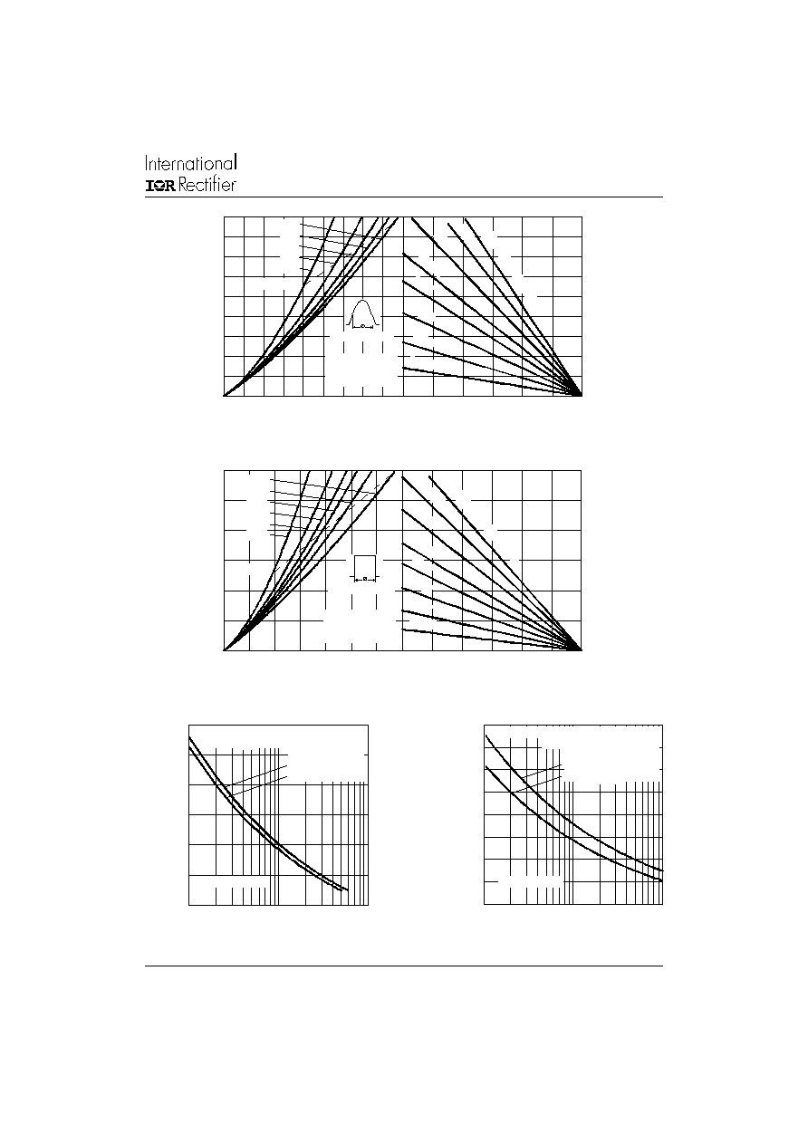
Fig. 6 - Forward Power Loss Characteristics
85HF(R) Series
7
Bulletin I20203 rev. A 09/98
www.irf.com
Fig. 9 - Maximum Non-Repetitive Surge Current
Fig. 10 - Maximum Non-Repetitive Surge Current
Fig. 7 - Forward Power Loss Characteristics
Fig. 8 - Forward Power Loss Characteristics
0
25
50
75
100
125
150
Maximum Allowable Ambient Temperature (�C)
1.5
K
/W
2 K
/W
3 K
/W
5 K/W
10 K/W
R
=
0
.5
K
/W
-
D
elt
a
R
0.
7 K
/W
1 K
/W
thS
A
0
10
20
30
40
50
60
70
80
90
0
10
20
30
40
50
60
70
80
90
Average Forward Current (A)
RMS Limit
M
a
x
i
m
u
m
A
v
e
r
age
F
o
r
w
ar
d
P
o
w
e
r
Los
s
(
W
)
Conduction Angle
180�
120�
90�
60�
30�
85HF(R) Series
(1400V to 1600V)
T = 150�C
J
0
25
50
75
100
125
150
Maximum Allowable Ambient Temperature (�C)
1.5
K/W
2 K
/W
3 K/W
5 K/W
10 K/W
R
=
0
.5
K
/W
-
D
elt
a R
0.
7 K
/W
1 K
/W
th
S
A
0
20
40
60
80
100
120
0
20
40
60
80
100
120
140
DC
180�
120�
90�
60�
30�
Average Forward Current (A)
RMS Limit
M
a
x
i
m
u
m
A
v
er
a
ge F
o
r
w
ar
d P
o
w
e
r
Lo
s
s
(
W
)
Conduction Period
85HF(R) Series
(1400V to 1600V)
T = 150�C
J
400
600
800
1000
1200
1400
1600
1
10
100
P
e
a
k
H
a
l
f
S
i
ne
W
a
v
e
F
o
r
w
ar
d
C
u
r
r
ent
(
A
)
Number Of Equal Amplitude Half Cycle Current Pulses (N)
85HF(R) Series
Initial T = T Max.
@ 60 Hz 0.0083 s
@ 50 Hz 0.0100 s
At Any Rated Load Condition And With
Rated V Applied Following Surge.
RRM
J
J
200
400
600
800
1000
1200
1400
1600
1800
0.01
0.1
1
P
eak
H
a
l
f
S
i
ne
W
a
v
e
F
o
r
w
ar
d
C
u
r
r
e
n
t
(
A
)
Pulse Train Duration (s)
Maximum Non Repetitive Surge Current
85HF(R) Series
Initial T = T Max.
No Voltage Reapplied
Rated V Reapplied
RRM
Versus Pulse Train Duration.
J
J
85HF(R) Series
8
Bulletin I20203 rev. A 09/98
www.irf.com
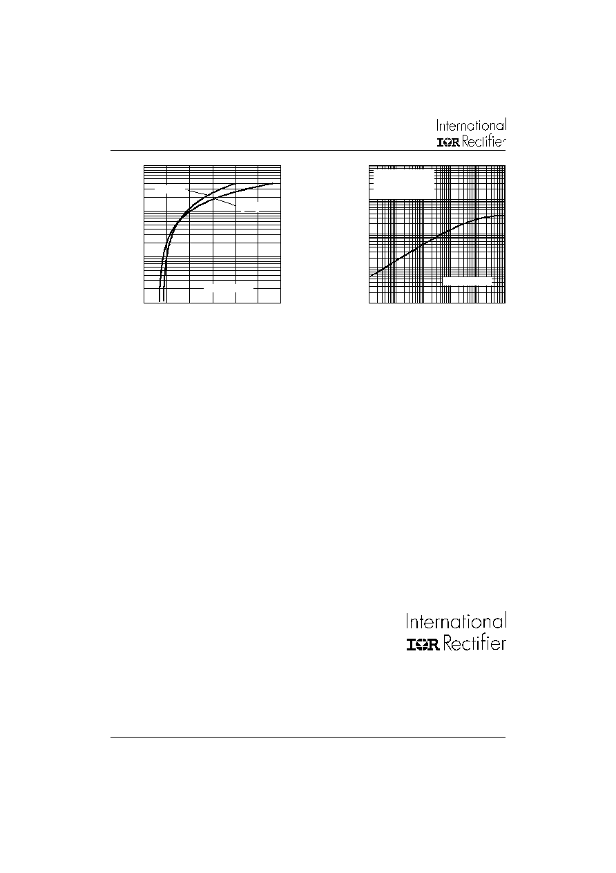
Fig. 11 - Forward Voltage Drop Characteristics
Fig. 12 - Thermal Impedance Z
thJC
Characteristics
10
100
1000
10000
0
1
2
3
4
5
6
T = 25�C
J
I
n
s
t
a
n
t
a
ne
ou
s
F
o
r
w
a
r
d C
u
r
r
en
t
(
A
)
Instantaneous Forward Voltage (V)
85HF(R) Series
T = T Max.
J
J
0.001
0.01
0.1
1
10
0.0001
0.001
0.01
0.1
1
10
Square Wave Pulse Duration (s)
th
J
C
T
r
a
n
s
i
e
n
t
T
h
e
r
m
a
l
Im
p
e
d
a
n
c
e
Z
(
K
/W
)
85HF(R) Series
Steady State Value
R = 0.35 K/W
(DC Operation)
thJC
WORLD HEADQUARTERS: 233 Kansas St., El Segundo, California 90245 U.S.A. Tel: (310) 322 3331. Fax: (310) 322 3332.
EUROPEAN HEADQUARTERS: Hurst Green, Oxted, Surrey RH8 9BB, U.K. Tel: ++ 44 1883 732020. Fax: ++ 44 1883 733408.
IR CANADA: 15 Lincoln Court, Brampton, Markham, Ontario L6T3Z2. Tel: (905) 453 2200. Fax: (905) 475 8801.
IR GERMANY: Saalburgstrasse 157, 61350 Bad Homburg. Tel: ++ 49 6172 96590. Fax: ++ 49 6172 965933.
IR ITALY: Via Liguria 49, 10071 Borgaro, Torino. Tel: ++ 39 11 4510111. Fax: ++ 39 11 4510220.
IR FAR EAST: K&H Bldg., 2F, 30-4 Nishi-Ikebukuro 3-Chome, Toshima-Ku, Tokyo, Japan 171. Tel: 81 3 3983 0086.
IR SOUTHEAST ASIA: 1 Kim Seng Promenade, Great World City West Tower,13-11, Singapore 237994. Tel: ++ 65 838 4630.
IR TAIWAN: 16 Fl. Suite D.207, Sec. 2, Tun Haw South Road, Taipei, 10673, Taiwan. Tel: 886 2 2377 9936.
http://www.irf.com
Fax-On-Demand: +44 1883 733420 Data and specifications subject to change without notice.