1
V
F
< 1.3V @ 8A
t
rr
= 80ns
V
RRM
= 1200V
QUIET
IR
Series
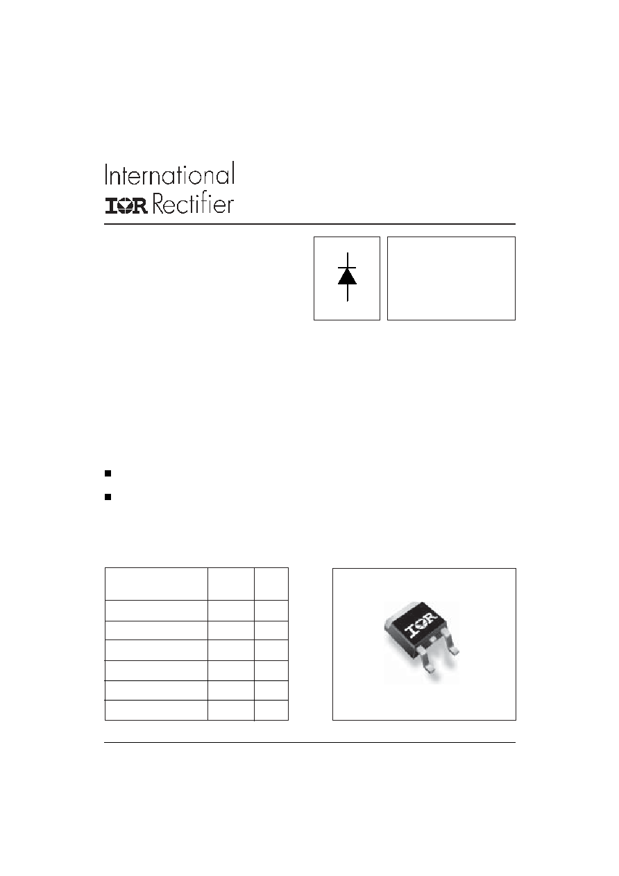
8EWF12S
Bulletin I2203 03/05
TO-252AA (D-Pak)
The 8EWF12SPbF fast soft recovery QUIET
IR
rectifier series has been optimized for combined
short reverse recovery time, low forward voltage
drop and low leakage current
The glass passivation ensures stable reliable
operation in the most severe temperature and
power cycling conditions.
Typical applications are both:
Output rectification and freewheeling diode
in
inverters, choppers and converters.
Input rectifications where severe
restrictions on conducted EMI should be met.
Description/ Features
Package Outline
I
F(AV)
Sinusoidal waveform
8
A
V
RRM
1200
V
I
FSM
170
A
V
F
@
8 A, T
J
= 25�C
1.3
V
t
rr
@ 1A, 100A/�s
80
ns
T
J
range
- 40 to 150
�C
Major Ratings and Characteristics
Characteristics
Values
Units
SURFACE MOUNTABLE FAST
SOFT RECOVERY DIODE
Lead-Free ("PbF" suffix)
www.irf.com
2
Bulletin I2203 03/05
8EWF12SPbF
QUIET
IR
Series
www.irf.com
I
F(AV)
Max. Average Forward Current
8
A
@ T
C
= 94� C, 180� conduction half sine wave
I
FSM
Max. Peak One Cycle Non-Repetitive
170
10ms Sine pulse, rated V
RRM
applied
Surge Current
200
10ms Sine pulse, no voltage reapplied
I
2
t
Max. I
2
t for fusing
144
10ms Sine pulse, rated V
RRM
applied
200
10ms Sine pulse, no voltage reapplied
I
2
t
Max. I
2
t for fusing
2000
A
2
s
t = 0.1 to 10ms, no voltage reapplied
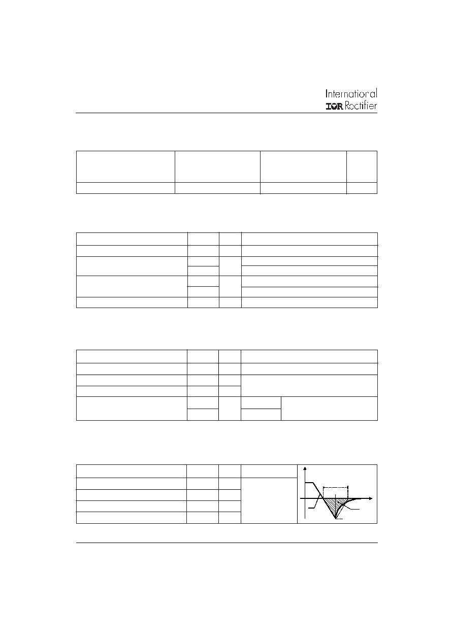
Voltage Ratings
Part Number
V
RRM
, maximum
V
RSM
, maximum non repetitive
I
RRM
peak reverse voltage
peak reverse voltage
150�C
V
V
mA
8EWF12SPbF
1200
1300
4
Absolute Maximum Ratings
Parameters
8EWF
Units
Conditions
t
rr
Reverse Recovery Time
270
ns
I
F
@ 8Apk
I
rr
Reverse Recovery Current
4.2
A
@ 25A/�s
Q
rr
Reverse Recovery Charge
1
�C
@ T
J
= 25�C
S
Typical Snap Factor tb/ta
0.6
-
Parameters
8EWF
Units
Conditions
A
A
2
s
V
FM
Max. Forward Voltage Drop
1.3
V
@ 8A, T
J
= 25�C
r
t
Forward slope resistance
25.6
m
V
F(TO)
Threshold voltage
0.93
V
I
RM
Max. Reverse Leakage Current
0.1
T
J
= 25 �C
4
T
J
= 150 �C
Electrical Specifications
Parameters
8EWF
Units
Conditions
T
J
= 150�C
V
R
= rated V
RRM
mA
Typical Reverse Recovery Characteristics
t
I
FM
t
rr
Q
rr
I
rr
di
dt
tb
ta

3
Bulletin I2203 03/05
8EWF12SPbF
QUIET
IR
Series
www.irf.com
T
J
Max. Junction Temperature Range
- 40 to 150
�C
T
stg
Max. Storage Temperature Range
- 40 to 150
�C
Soldering Temperature
240
�C
for 10 seconds
R
thJC
Max. Thermal Resistance Junction
2.5
�C/W
DC operation
to Case
R
thJA
Typ. Thermal Resistance Junction
50
�C/W
to Ambient (PCB Mount)**
wt
Approximate Weight
1(0.03)
g (oz.)
T
Case Style
TO-252AA (D-Pak)
Marking Device
8EWF12S
Thermal-Mechanical Specifications
Parameters
8EWF
Units
Conditions
** When mounted on 1" square (650mm
2
) PCB of FR-4 or G-10 material 4 oz (140�m) copper 40�C/W
For recommended footprint and soldering techniques refer to application note #AN-994
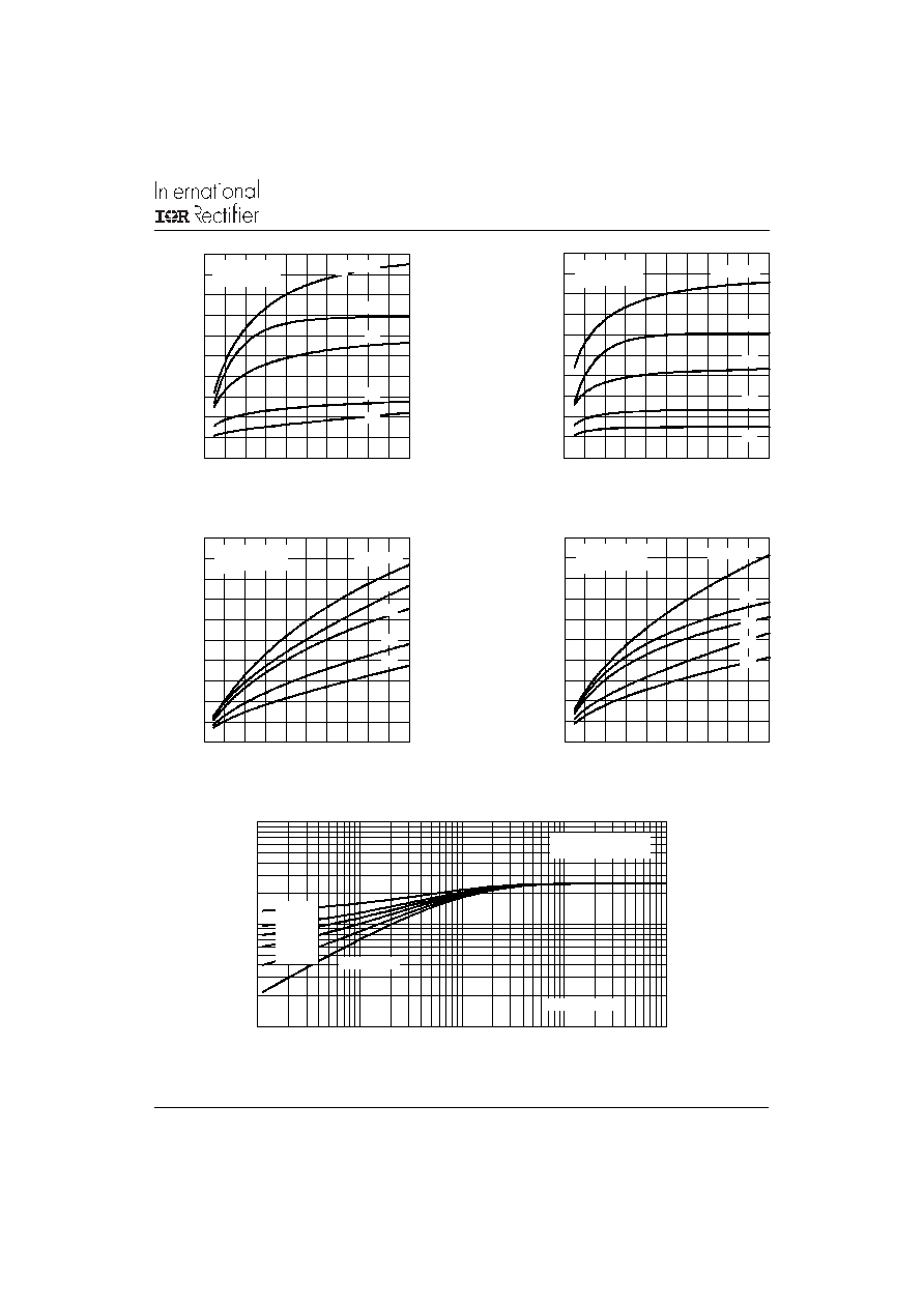
Fig. 1 - Current Rating Characteristics
Fig. 3 - Forward Power Loss Characteristics
Fig. 4 - Forward Power Loss Characteristics
Fig. 2 - Current Rating Characteristics
60
70
80
90
100
110
120
130
140
150
0
1
2
3
4
5
6
7
8
9
30�
60�
90�
120�
180�
Ma
x
i
mu
m
A
l
l
o
w
a
b
l
e
C
a
s
e
T
e
mp
e
r
a
t
u
r
e
(
�
C
)
Conduction Angle
Average Forward Current (A)
8EWF..S Series
R (DC) = 2.5 �C/ W
thJC
60
70
80
90
100
110
120
130
140
150
0
2
4
6
8
10
12
14
DC
30� 60�
90�
120�
180�
M
a
x
i
m
u
m
A
llo
w
a
b
l
e
C
a
s
e
T
em
per
at
u
r
e (
�
C
)
Cond uction Period
Average Forward Current (A)
8EWF..S Series
R (DC) = 2.5 �C/ W
thJC
0
2
4
6
8
10
12
0
1
2
3
4
5
6
7
8
9
RMS Limit
180�
120�
90�
60�
30�
Cond uction Angle
Average Forward Current (A)
M
a
x
i
m
u
m
A
v
e
r
age
F
o
r
w
ar
d P
o
we
r
L
o
s
s
(W
)
8EWF..S Series
T = 150�C
J
0
2
4
6
8
10
12
14
16
18
0
2
4
6
8
10
12
14
DC
180�
120�
90�
60�
30�
RMS Limit
Conduction Period
Average Forward Current (A)
M
a
x
i
m
u
m
A
v
e
r
ag
e F
o
r
w
ar
d P
o
w
e
r
L
o
s
s
(
W
)
8EWF..S Series
T = 150�C
J

4
Bulletin I2203 03/05
8EWF12SPbF
QUIET
IR
Series
www.irf.com
Fig. 6 - Maximum Non-Repetitive Surge Current
Fig. 5 - Maximum Non-Repetitive Surge Current
Fig. 7 - Forward Voltage Drop Characteristics
Fig. 8 - Recovery Time Characteristics, T
J
= 25�C
Fig. 9 - Recovery Time Characteristics, T
J
= 150�C
80
90
100
110
120
130
140
150
160
170
180
1
10
100
Number Of Equal Amplitude Half Cycle Current Pulses (N)
P
e
a
k
H
a
l
f
S
i
n
e
W
a
v
e
F
o
rw
a
r
d
C
u
rre
n
t
(
A
)
Initial T = 150�C
@ 60 Hz 0.0083 s
@ 50 Hz 0.0100 s
J
At Any Rated Load Condition And With
Rated V Applied Following Surge.
RRM
8EWF..S Series
80
90
100
110
120
130
140
150
160
170
180
190
200
0.01
0.1
1
Pulse Train Duration (s)
P
e
a
k
H
a
l
f
S
i
ne
W
a
v
e
F
o
r
w
ar
d C
u
r
r
e
n
t
(
A
)
Versus Pulse Train Duration.
Initial T = 150�C
No Voltage Reapplied
Rated V Reapplied
RRM
J
Maximum Non Repetitive Surge Current
8EWF..S Series
1
10
100
1000
0.5
1
1.5
2
2.5
3
3.5
4
4.5
T = 25�C
J
I
n
s
t
a
n
t
a
ne
ou
s
F
o
r
w
a
r
d
Cur
r
ent
(
A
)
Instantaneous Forward Voltage (V)
T = 150�C
J
8EWF..S Series
0
0.1
0.2
0.3
0.4
0.5
0.6
0
40
80
120
160
200
Rate Of Fall Of Forward Current - di/ dt (A/ �s)
1 A
5 A
M
a
x
i
mu
m R
e
v
e
r
s
e
R
e
c
o
v
e
r
y
T
i
me
-
T
r
r
(
�
s
)
8EWF..S Series
T = 25 �C
J
8 A
2 A
I = 10 A
FM
0
0.2
0.4
0.6
0.8
0
40
80
120
160
200
Rate Of Fall Of Forward Current - di/ dt (A/ �s)
1 A
5 A
M
a
x
i
m
u
m
R
e
v
e
rs
e
R
e
c
o
v
e
ry
T
i
m
e
- T
rr (
�
s
)
8EWF..S Series
T = 150 �C
J
I = 10 A
FM
2 A
8 A
5
Bulletin I2203 03/05
8EWF12SPbF
QUIET
IR
Series
www.irf.com
Fig. 10 - Recovery Charge Characteristics, T
J
= 25�C
Fig. 11 - Recovery Charge Characteristics, T
J
= 150�C
Fig. 12 - Recovery Current Characteristics, T
J
= 25�C
Fig. 13 - Recovery Current Characteristics, T
J
= 150�C
Fig. 14 - Thermal Impedance Z
thJC
Characteristics
0
0.4
0.8
1.2
1.6
2
0
40
80
120
160
200
Rate Of Fall Of Forward Current - di/ dt (A/ �s)
1 A
5 A
M
a
x
i
mu
m R
e
v
e
r
s
e
R
e
c
o
v
e
r
y
C
h
a
r
g
e
-
Q
r
r
(
�
C
)
8EWF..S Series
T = 25 �C
J
I = 10 A
FM
2 A
8 A
0
1
2
3
4
5
0
40
80
120
160
200
Rate Of Fall Of Forward Current - di/ dt (A/ �s)
1 A
5 A
M
a
x
i
m
u
m
R
e
v
e
r
s
e R
e
c
o
v
e
r
y
Char
ge
-
Q
r
r
(
�
C
)
8EWF..S Series
T = 150 �C
J
I = 10 A
FM
2 A
8 A
0
4
8
12
16
20
0
40
80
120
160
200
M
a
xi
m
u
m
R
e
v
e
rs
e
R
e
c
o
v
e
ry
C
u
rr
e
n
t
-
I
r
r
(
A
)
Rate Of Fall Of Forward Current - di/ dt (A/ �s)
1 A
5 A
8 A
2 A
I = 10 A
FM
8EWF..S Series
T = 25 �C
J
0
5
10
15
20
25
0
40
80
120
160
200
M
a
x
i
m
u
m
R
e
v
e
rs
e
R
e
c
o
v
e
ry
C
u
rr
e
n
t
-
I
r
r (
A
)
Rate Of Fall Of Forward Current - di/ dt (A/ �s)
1 A
5 A
8EWF..S Series
T = 150 �C
J
I = 10 A
FM
8 A
2 A
0.1
1
10
0.0001
0.001
0.01
0.1
1
Square Wave Pulse Duration (s)
Steady State Value
(DC Operation)
Single Pulse
th
JC
T
r
an
s
i
e
n
t
T
h
er
m
a
l
I
m
p
e
da
n
c
e Z
(
�
C
/
W
)
8EWF..S Series
D = 0.50
D = 0.33
D = 0.25
D = 0.17
D = 0.08
6
Bulletin I2203 03/05
8EWF12SPbF
QUIET
IR
Series
www.irf.com
8EWF12S
ASSEMBLED ON WW 12, 2003
THIS IS A 8EWF12S WITH
LOT CODE 5K3A
RECTIFIER
LOGO
LOT CODE
ASSEMBLY
INTERNATIONAL
PART NUMBER
DATE CODE
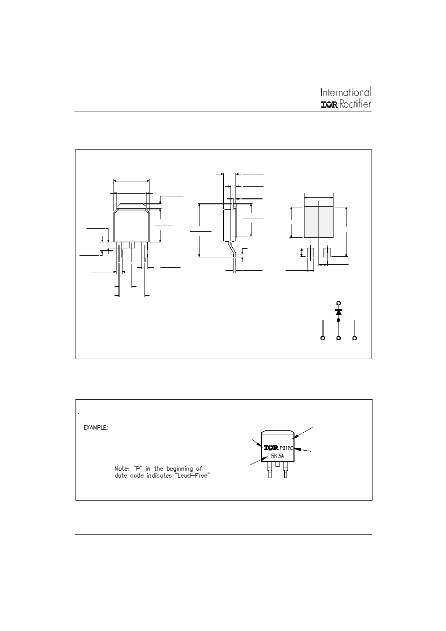
P = LEAD-FREE
YEAR 3 = 2003
WEEK 12
LINE C
IN THE ASSEMBLY LINE "C"
Dimensions in millimeters and (inches)
Outline Table
6.73 (0.26)
6.35 (0.25)
5.46 (0.21)
5.21 (0.20)
4
1.27 (0.05)
0.88 (0.03)
5.97 (0.23)
1 - Anode
2 - Cathode
3 - Anode
4 - Cathode
1.64 (0.02)
1.52 (0.06)
1.15 (0.04)
1.14 (0.04)
0.76 (0.03)
2x
2.28 (0.09)
2x
0.89 (0.03)
0.64 (0.02)
3x
4.57 (0.18)
1
2
3
6.22 (0.24)
2.38 (0.09)
2.19 (0.08)
6.45 (0.24)
5.68 (0.22)
10.42 (0.41)
9.40 (0.37)
0.46 (0.02)
0.58 (0.02)
1.14 (0.04)
0.89 (0.03)
0.51 (0.02)
MIN.
0.58 (0.02)
0.46 (0.02)
MINIMUM RECOMMENDED FOOTPRINT
5.97 (0.24)
10.67 (0.42)
1.65 (0.06)
6.48 (0.26)
2x
2.54 (0.10)
2x
2.28 (0.09)
2x
BASE
CATHODE
CATHODE ANODE
ANODE
4
1
2
3
Marking Information
7
Bulletin I2203 03/05
8EWF12SPbF
QUIET
IR
Series
www.irf.com
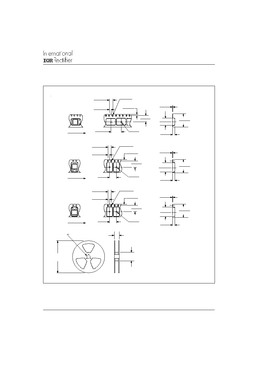
Tape & Reel Information
TR
FEED DIRECTION
4.1 (0.16)
3.9 (0.15)
2.1 (0.83)
1.9 (0.07)
12.1 (0.48)
1.65 (0.06)
1.85 (0.07)
1.65 (0.06)
7.4 (0.29)
2.6 (0.10)
1.5 (0.06)
7.6 (0.30)
11.9 (0.47)
1.85 (0.07)
TO-252AA Tape & Reel
When ordering, indicate the part
number, part orientation, and the
quantity. Quantities are in multiples
of 2,000 pieces per reel for TR and
multiples of 3,000 pieces per reel
for both TRL and TRR.
13 (0.52) DIA.
DIA. MAX.
375 (14.17)
50 (1.97) DIA.
22.4 (0.88)
0.35 (0.01)
16.3 (0.64)
15.7 (0.62)
2.75 (0.11)
2.55 (0.10)
0.25 (0.01)
6.8 (0.26)
7.0 (0.28)
TRR
FEED DIRECTION
4.1 (0.16)
3.9 (0.15)
2.1 (0.83)
1.9 (0.07)
8.1 (0.32)
1.85 (0.07)
1.65 (0.06)
1.85 (0.07)
1.65 (0.06)
7.4 (0.29)
2.6 (0.10)
1.5 (0.06)
7.6 (0.30)
7.9 (0.31)
0.35 (0.01)
16.3 (0.64)
15.7 (0.62)
2.75 (0.11)
2.55 (0.10)
0.25 (0.01)
10.4 (0.41)
10.6 (0.42)
DIA.
TRL
FEED DIRECTION
4.1 (0.16)
3.9 (0.15)
2.1 (0.83)
1.9 (0.07)
8.1 (0.32)
1.85 (0.07)
1.65 (0.06)
1.85 (0.07)
1.65 (0.06)
7.4 (0.29)
2.6 (0.10)
1.5 (0.06)
7.6 (0.30)
7.9 (0.31)
0.35 (0.01)
16.3 (0.64)
15.7 (0.62)
2.75 (0.11)
2.55 (0.10)
0.25 (0.01)
10.4 (0.41)
10.6 (0.42)
DIA.
DIA.
DIA.
DIA.
DIA.

8
Bulletin I2203 03/05
8EWF12SPbF
QUIET
IR
Series
www.irf.com
Ordering Information Table
1
5
2
4
3
6
7
1
-
Current Rating (8 = 8A)
2
-
Circuit Configuration:
E = Single Diode
3
-
Package:
W = D-Pak
4
-
Type of Silicon:
F = Fast Soft Recovery Rectifier
5
-
Voltage Rating (12 = 1200V)
6
-
S = Surface Mountable
7
-
TR
= Tape & Reel
TRR = Tape & Reel (Right Oriented)
TRL = Tape & Reel (Left Oriented)
8
-
none = Standard Production
PbF = Lead-Free
Device Code
IR WORLD HEADQUARTERS: 233 Kansas St., El Segundo, California 90245, USA Tel: (310) 252-7105
TAC Fax: (310) 252-7309
Visit us at www.irf.com for sales contact information. 03/05
Data and specifications subject to change without notice.
This product has been designed and qualified for Industrial Level and Lead-Free.
Qualification Standards can be found on IR's Web site.
8
E
W
F
12
S
TR PbF
8