/home/web/doc/html/irf/169911
DF...
Units Conditions
I
O
Maximum DC output
1.0
A
T
amb
= 40
o
C, Resistive or inductive load
current
0.8
A
T
amb
= 40
o
C, Capacitive load
I
FSM
Maximum peak one
30
A
t = 10ms, 20ms
Following any rated
cycle, non-repetitive
31
A
t = 8.3ms, 16.7ms
load condition and with
surge current
rated V
RRM
reapplied
I
2
t
Maximum I
2
t capability
4.5
A
2
s
t = 10ms
Initial T
J
= T
J
max
for fusing
4.1
A
2
s
t = 8.3ms
100% V
RRM
reapplied
6.4
A
2
s
t = 10ms
Initial T
J
= T
J
max
5.8
A
2
s
t = 8.3ms
no voltage reapplied
I
2
t
Maximum I
2
t
64
A
2
s
t = 0.1 to 10ms, no voltage reapplied
capability for fusing
V
FM
Maximum peak forward
1.0
V
I
FM
= 1.0A, T
J
= 25
o
C
voltage per diode
I
RM
Typical peak reverse
5
�A
T
J
= 25
o
C, 100% V
RRM
leakage per diode
100
�A
T
J
= 150
o
C, 100% V
RRM
f
Operating frequency
50 to 1000
Hz
range
V
RRM
Maximum repetitive peak
50 to 1000
V
reverse voltage range
DF...
Units Conditions
T
J
Operating and storage
- 55 to 150
o
C
T
stg
temperature range
R
thJA
Thermal resistance,
60
K/W
junctions to ambient
W
Approximate weight
0.6 (0.02)
g (oz)
I
O(av)
= 1.0 A
V
RRM
range
50 to 1000V
Bulletin U2788 rev. G 04/03
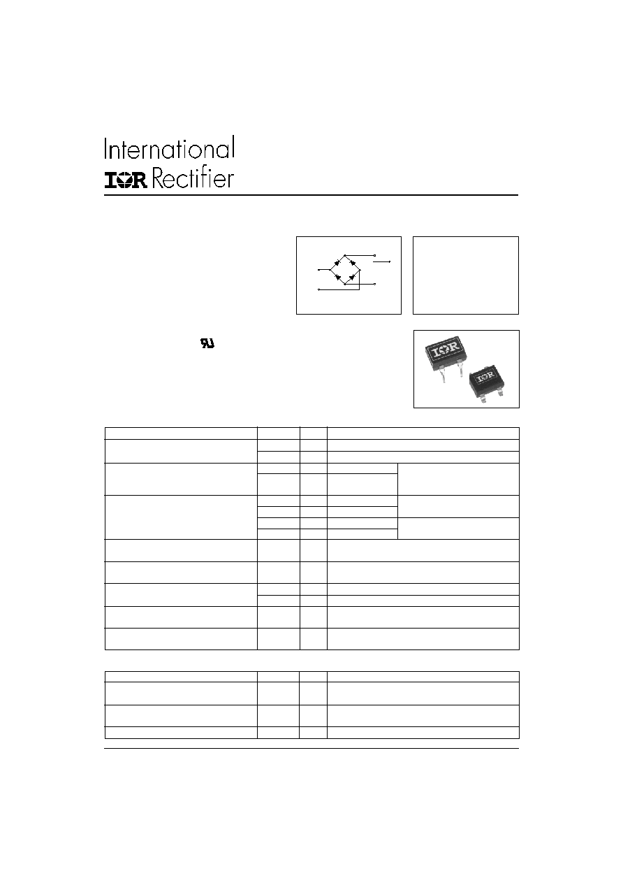
DF SERIES
1A Single Phase D.I.L. Rectifier Bridge
+
-
~
~
I
O(av)
Electrical Specification
Thermal and Mechanical Specifications
The DF Series of Single Phase Rectifier Bridges
consists of four silicon junctions encapsulated in a 4
pin D.I.L. package. These devices are intended for
general use in industrial and consumer equipment.
Description
1
www.irf.com
� Glass passivated chips
� Leads on standard 0.1" grid
� Suitable for automatic insertion
� High surge current capability
� Fully characterised data
� Wide temperature range
� Surface mount option
� Lead free terminals solderable as per
MIL-STD-750 Method 2026
� High temperature soldering guaranteed 260�C/8-10 secs
� Polarity symbols marked on the case
� UL E160375 approved
Features
DF SERIES
Bulletin U2788 rev. G 04/03
2
www.irf.com
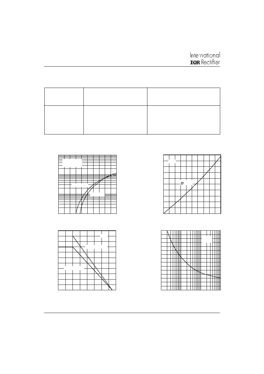
Fig. 3 - Current Ratings
Part Number
V
RRM
. Maximum repetitive
V
RSM
. Maximum non-
peak reverse
repetitive peak
voltage
reverse voltage
V
V
DF005M/DF005S
50
80
DF01M/DF01S
100
150
DF02M/DF02S
200
300
DF04M/DF04S
400
500
DF06M/DF06S
600
700
DF08M/DF08S
800
900
DF10M/DF10S
1000
1100
Voltage Specifications
Fig. 1 - Forward Characteristics
Fig. 2 - Power Loss Characteristics
Fig. 4 - Non-Repetititive Surge Ratings
Instantaneous Forward Current (A)
Instantaneous Forward Voltage (V)
Average Output Current (A)
Maximum Total Power Loss (W)
Maximum Allowable Ambient Temperature (�C)
Average Output Current (A)
Pulse Train Duration (s)
Maximum Peak Surge Current (A)
100
10
1
0.1
0
0.4
0.8
1.2
1.6
2.0
Tj = 25�C
Tj = 150�C
DF...
Per Junction
0
0.2
0.4
0.6
0.8
1.0
2.0
1.8
1.6
1.4
1.2
1.0
0.8
0.6
0.4
0.2
0
= 180�
DF...
Capacitive Load
0
20
40
60
80
100 120 140 160
1.1
1.0
0.9
0.8
0.7
0.6
0.5
0.4
0.3
0.2
0.1
0
Resistive Load
DF...
50Hz
10
10
1
10
30
28
26
24
22
20
18
16
14
12
10
8
6
4
2
0
- 2
- 1
DF...
3
DF SERIES
Bulletin U2788 rev. G 04/03
www.irf.com
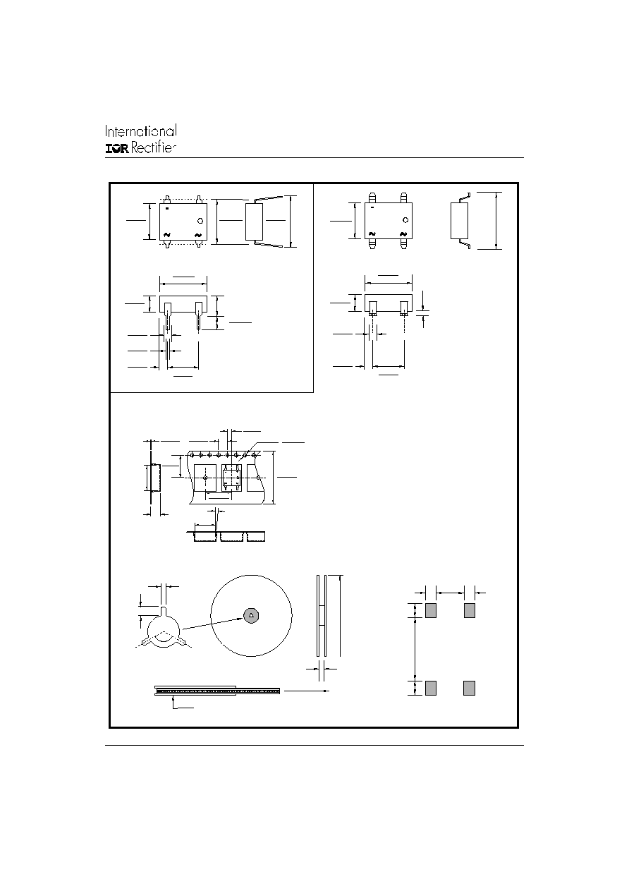
All dimensions in millimetres(inches)
DF..S
DF..M
3.5(0.138)
1.5(0.059)
1.5(0.059)
Footprint and Pad Dimensions
6.40(0.252)
6.10(0.240)
6.40(0.252)
6.10(0.240)
8.40(0.331)
8.10(0.319)
8.40(0.331)
8.10(0.319)
3.30(0.130)
3.10(0.122)
3.30(0.130)
3.10(0.122)
1.2(0.047)
1.0(0.040)
1.2(0.047)
1.0(0.040)
0.51(0.020)
0.41(0.016)
1.40(0.055)
1.14(0.045)
1.40(0.055)
1.14(0.045)
5.33(0.210)
4.83(0.210)
2.00(0.079)
16.0(0.630)
330(12.99)
3.50(0.138)
Identification Label
Unreel Direction
5.33(0.210)
4.83(0.210)
2.80(0.110)
1.60(0.063)
8.13(0.320)
7.11(0.280)
8.38(0.330)
7.62(0.300)
10.4 (0.409)
Max.
5.10(0.201)
Max.
+
+
9a
9b
Tape Reel
2.1(0.083)
1.9(0.075)
1.60(0.063)
1.50(0.060)
16.3(0.642)
15.7(0.618)
7.6(0.299)
7.4(0.291)
10.70(0.421)
12.10(0.476)
11.90(0.469)
3.8(0.150)
8.7(0.343)
5o
4.10(0.161)
3.90(0.154)
0.35(0.014)
0.25(0.010)
dia.
Tape Colour - Black
2.0(0.079)
2.0(0.079)
8.0(0.315)
Tape Reel Dimensions for DF15...TRR16
0.30(0.012)
Max.
DF SERIES
Bulletin U2788 rev. G 04/03
4
www.irf.com
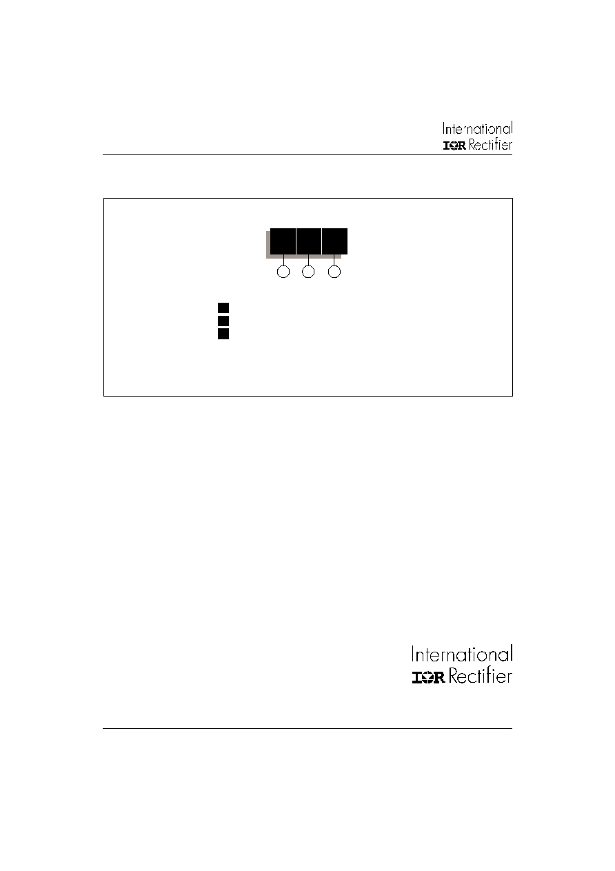
Ordering Information Table
Device Code
1
2
3
DF
10
S
To specify tape reel option add ' TRR16' suffix. e.g. DF10STRR16
1
-
Basic Part Number
2
-
Voltage Code: Code x 100 = V
RRM
3
-
Terminal Type: M
= hole mount
S
= surface mount
IR WORLD HEADQUARTERS: 233 Kansas St., El Segundo, California 90245, USA Tel: (310) 252-7105
TAC Fax: (310) 252-7309
Visit us at www.irf.com for sales contact information. 04/03
Data and specifications subject to change without notice.
This product has been designed and qualified for Multiple Level.
Qualification Standards can be found on IR's Web site.