 | –≠–ª–µ–∫—Ç—Ä–æ–Ω–Ω—ã–π –∫–æ–º–ø–æ–Ω–µ–Ω—Ç: GBPC3502W | –°–∫–∞—á–∞—Ç—å:  PDF PDF  ZIP ZIP |
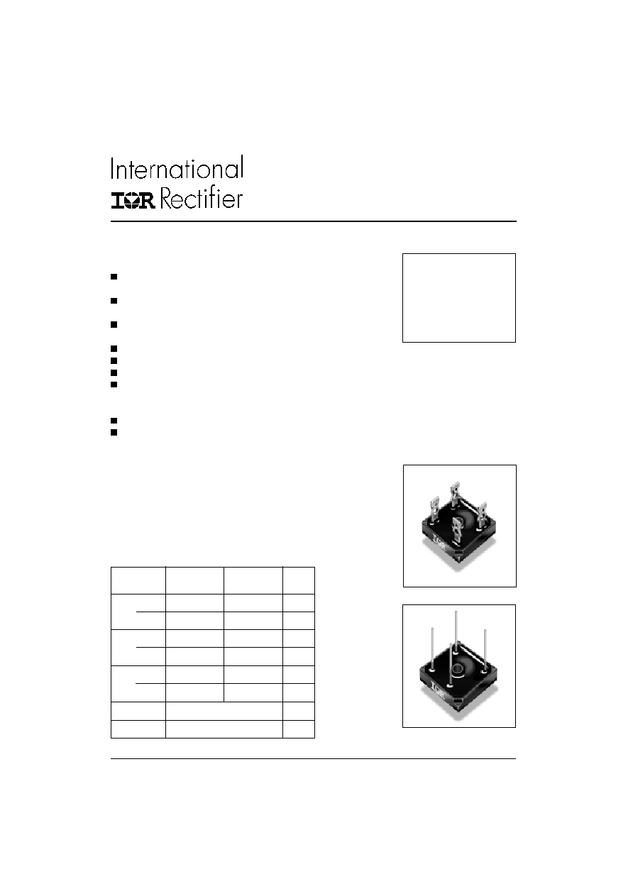
SINGLE PHASE BRIDGE
Power Modules
25 A
35 A
GBPC.. Series
1
Bulletin I27505 rev. F 03/03
www.irf.com
Features
Universal, 3 way terminals:
push-on, wrap around or solder
High thermal conductivity package,
electrically insulated case
Polarity symbols are moulded on
body of the plastic box
Center hole fixing
Glass passivated diode chips
Excellent power/ volume ratio
Nickel plated terminals suitable for High Temperature
soldering at 250 - 260∞C
max. time 8 - 10 seconds
Wire lead version available
UL E 62320 approved
Description
A range of extremely compact, encapsulated
single phase bridge rectifiers offering efficient and
reliable operation. They are intended for use in
general purpose and instrumentation applica-
tions.
Parameters
GBPC25
GBPC35
Units
Major Ratings and Characteristics
I
O
25
35
A
@ T
C
60
55
o
C
I
FSM
@
50Hz
400
475
A
@ 60Hz
420
500
A
I
2
t
@ 50Hz
790
1130
A
2
s
@ 60Hz
725
1030
A
2
s
V
RRM
range
200 to 1200
V
T
J
-55 to 150
o
C
GBPC...A
GBPC...W

GBPC.. Series
2
Bulletin I27505 rev. F 03/03
www.irf.com
I
O
Maximum DC output current
25
35
A
Resistive or inductive load
20
28
A
Capacitive load
@ Case temperature
60
55
∞C
I
FSM
Maximum peak, one-cycle
400
475
A
t = 10ms
No voltage
Initial T
J
=T
J
max.
non-repetitive forward current
420
500
t = 8.3ms
reapplied
335
400
t = 10ms
100% V
RRM
350
420
t = 8.3ms
reapplied
I
2
t
Maximum I
2
t for fusing
790
1130
A
2
s
t = 10ms
No voltage
725
1030
t = 8.3ms
reapplied
560
800
t = 10ms
100% V
RRM
512
730
t = 8.3ms
reapplied
I
2
t
Maximum I
2
t for fusing
7.9
11.3
KA
2
s I
2
t for time t
x
= I
2
t x
t
x
;
0.1
t
x
10ms, V
RRM
= 0V
V
F(TO)1
Low-level of threshold voltage
0.76
0.77
V
(16.7% x
x I
F(AV)
< I <
x I
F(AV)
), @ T
J
max.
V
F(TO)2
High-level of threshold voltage
0.89
0.92
(I >
x I
F(AV)
), @ T
J
max.
r
t1
Low-level forward slope resistance
8.2
4.852
m
(16.7% x
x I
F(AV)
< I <
x I
F(AV)
), @ T
J
max.
r
t2
High-level forward slope resistance
6.8
3.867
(I >
x I
F(AV)
), @ T
J
max.
V
FM
Maximum forward voltage drop
1.1
1.1
V
T
J
= 25
o
C, I
FM
= I
Favg (arm)
I
RRM
Max. DC reverse current
5.0
5.0
µ
A
T
J
= 25
o
C, per diode at V
RRM
V
INS
RMS isolation voltage base plate
2700
2700
V
f = 50 Hz, t = 1s
Forward Conduction
Voltage
V
RRM
, max repetitive
V
RSM
, max non-repetitive
I
RRM
max.
I
RRM
max.
Type number Code
peak AC rev. voltage
peak AC rev. voltage
@ rated V
RRM
D.C. rev. curr.
T
J
= T
J
max.
T
J
= T
J
max.
T
J
= T
J
max.
@ T= 125∞C
V
V
mA
(µA)
02
200
275
2
500
GBPC25/35..A
04
400
500
2
500
GBPC25/35..W
06
600
725
2
500
(*)
08
800
900
2
500
10
1000
1100
2
500
12
1200
1300
2
500
ELECTRICAL SPECIFICATIONS
Voltage Ratings
Parameters
GBPC25
GBPC35
Units Conditions
(*) please see Ordering Information Table - page 3

GBPC.. Series
3
Bulletin I27505 rev. F 03/03
www.irf.com
T
J
Junction temperature range
-55 to 150
o
C
T
stg
Storage temperature range
-55 to 150
o
C
R
thJC
Max. thermal resistance junct. to case
1.7
1.4
K/W
DC operation per bridge
R
thCS
Max. thermal resist., case to heatsink
0.2
K/W
Mounting surface , smooth, flat and greased
wt
Approximate weight
16
g
T
Mounting Torque
±
10%
2.0
Nm
Bridge to heatsink
Parameters
GBPC25
GBPC35
Units Conditions
25
= 25A (Avg)
35
= 35A (Avg)
1
-
Circuit configuration:
Single phase bridge coding
2
-
Current rating code:
3
-
Voltage Code: code x 100 = V
RRM
4
-
Diode bridge rectifier:
A
=
Standard Fasten Terminal
W
=
Wire Lead
GBPC
35
12
A
1
2
3
4
Thermal and Mechanical Specifications
Ordering Information Table
Device Code
Outline Table
All dimensions are in millimeters
GBPC...A
GBPC...W
AC1
AC1
AC2
AC2

GBPC.. Series
4
Bulletin I27505 rev. F 03/03
www.irf.com
Fig. 2 - Forward Voltage Drop Characteristics
Fig. 1 - Current Ratings Characteristics
Fig. 3 - Total Power Loss Characteristics
Fig. 4 - Maximum Non-Repetitive Surge Current
Fig. 5 - Maximum Non-Repetitive Surge Current
50
60
70
80
90
100
110
120
130
140
150
0
5
10
15
20
25
30
180∞
(Sine)
180∞
(Rect)
GBPC25.. Series
Instantaneous Forward Voltage (V)
Instantaneous Forward Current (A)
Maximum Allowable Case Temperature (∞C)
Average Forward Current (A)
Average Forward Current (A)
Maximum Allowable Ambient Temperature ∞C
Number of Equal Amplitude Half Cycle Current Pulses (N)
Pulse Train Duration (s)
Peak Half Sine Wave Forward Current (A)
Peak Half Sine Wave Forward Current (A)
Maximum Average Forward Power Loss
(W)
50
100
150
200
250
300
350
400
0.01
0.1
1
Maximum Non Repetitive Surge Current
Initial T = 150∞C
No Voltage Reapplied
Rated V Reapplied
Versus Pulse Train Duration.
RRM
J
GBPC25.. Series
100
150
200
250
300
350
400
1
10
100
Initial T = 150∞C
@ 60 Hz 0.0083 s
@ 50 Hz 0.0100 s
At Any Rated Load Condition And With
Rated V Applied Following Surge.
RRM
J
GBPC25.. Series
25
50
75
100
3 K/W
1 K/W
R = 0.7 K/W - Delta R
thSA
2 K/W
0
10
20
30
40
50
0
5
10
15
20
25
180∞
(Sine)
180∞
(Rect)
GBPC25.. Series
T = 150∞C
J
1
10
100
1000
0.5
1
1.5
2
2.5
T = 25∞C
J
T = 150∞C
J
GBPC25.. Series

GBPC.. Series
5
Bulletin I27505 rev. F 03/03
www.irf.com
Fig. 6 - Current Ratings Characteristics
Fig. 7 - Forward Voltage Drop Characteristics
Fig. 8 - Total Power Loss Characteristics
Fig. 9 - Maximum Non-Repetitive Surge Current
Fig. 10 - Maximum Non-Repetitive Surge Current
Instantaneous Forward Voltage (V)
Average Forward Current (A)
Maximum Allowable Case Temperature (∞C)
Instantaneous Forward Current (A)
Maximum Average Forward Power Loss
(W)
Peak Half Sine Wave Forward Current (A)
Peak Half Sine Wave Forward Current (A)
Average Forward Current (A)
Maximum Allowable Ambient Temperature ∞C
100
150
200
250
300
350
400
450
1
10
100
GBPC35.. Series
At Any Rated Load Condition And With
Rated Vrrm Applied Following Surge.
Initial Tj = 150∞C
@ 60 Hz 0.0083 s
@ 50 Hz 0.0100 s
100
150
200
250
300
350
400
450
500
0.01
0.1
1
Maximum Non Repetitive Surge Current
GBPC35.. Series
Versus Pulse Train Duration.
Initial Tj = 150∞C
No Voltage Reapplied
Rated Vrrm Reapplied
1
10
100
1000
0.5
1
1.5
2
2.5
3
T = 25∞C
J
GBPC35.. Series
T = 150∞C
J
40
50
60
70
80
90
100
110
120
130
140
150
0
10
20
30
40
180∞
(Sine)
180∞
(Rect)
GBPC35.. Series
Number of Equal Amplitude Half Cycle Current Pulses (N)
Pulse Train Duration (s)
25
50
75
100
1 K/W
0.7 K/W
3 K/W
2 K/W
R thSA = 0.5 K/W - Delta R
0
10
20
30
40
50
60
70
80
0
5
10
15
20
25
30
35
180∞
(Sine)
180∞
(Rect)
GBPC35.. Series
T = 150∞C
J