1
www.irf.com
International Rectifier
·
233 Kansas Street, El Segundo, CA 90245 USA
Features
!
Drives:
1 x 32W T8 Lamp
!
Input:
90-140VAC/60Hz
!
High Power Factor/Low THD
!
High Frequency Operation
!
Lamp Filament Preheating
!
Lamp Fault Protection with Auto-Restart
!
Brownout Protection
!
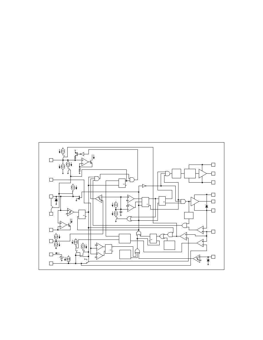
IR21592 HVIC Ballast Controller
Description
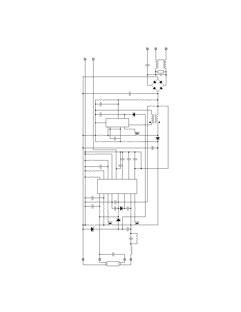
The IRPLDIM1U is a high efficiency, high power factor, dim-
ming electronic ballast designed for driving rapid start fluo-
rescent lamp types. The design contains an EMI filter, ac-
tive power factor correction and a ballast control circuit us-
ing the IR21592. This demo board is intended to ease the
evaluation of the IR21592 Dimming Ballast Control IC,
demonstrate PCB layout techniques and serve as an aid
IR21592 Dimming Ballast Control IC Design Kit
in the development of production ballast's using the IR21592.
IRPLDIM1U
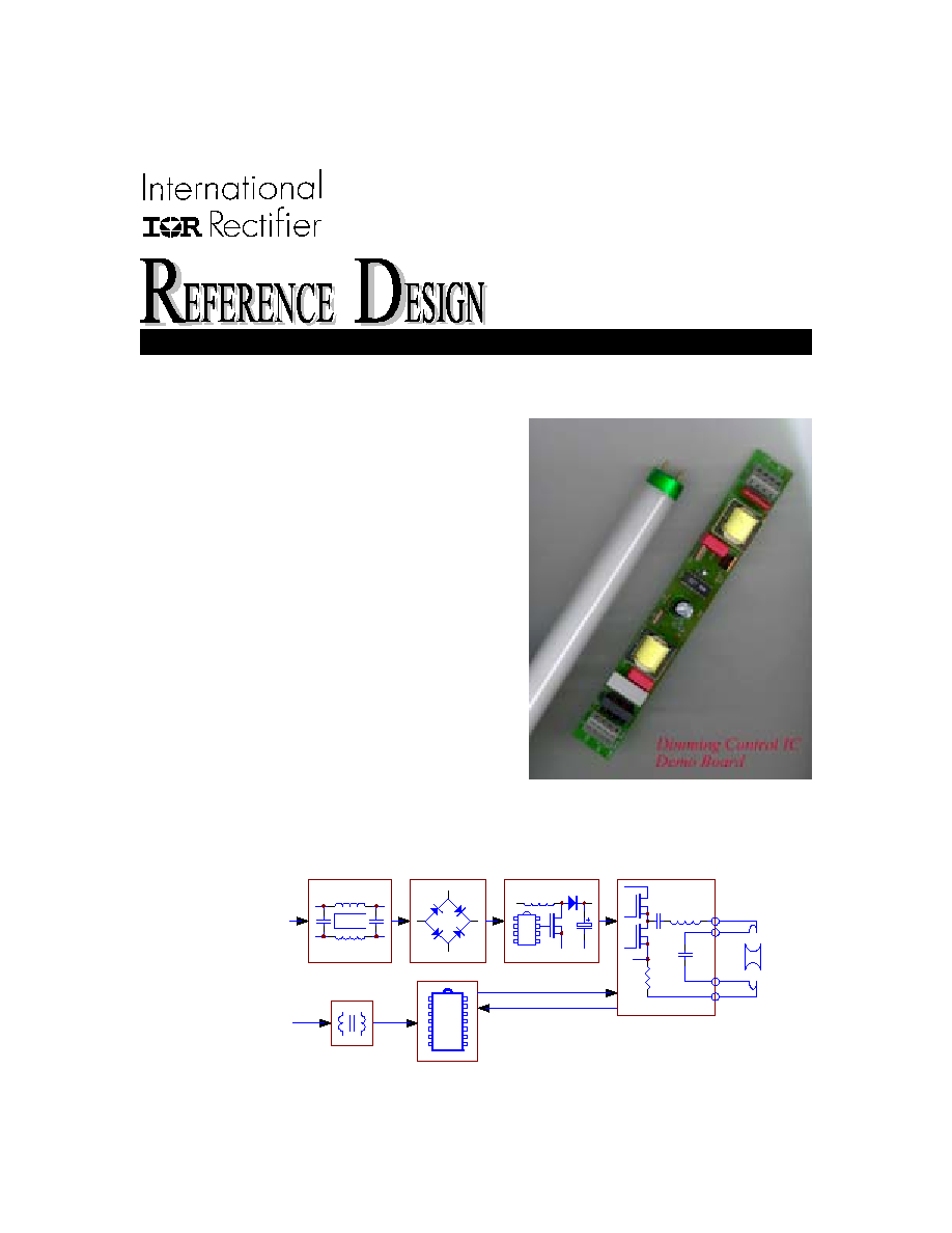
EMI Filter
Half-Bridge Driver
Rectifier
Lamp Fault
Line
IR21592
Dimming Feedback
Preheat Feedback
Interface
Dim
Input
PFC
Output Stage
Lamp
Dimming Ballast
Block Diagram
IR21592
4
www.irf.com
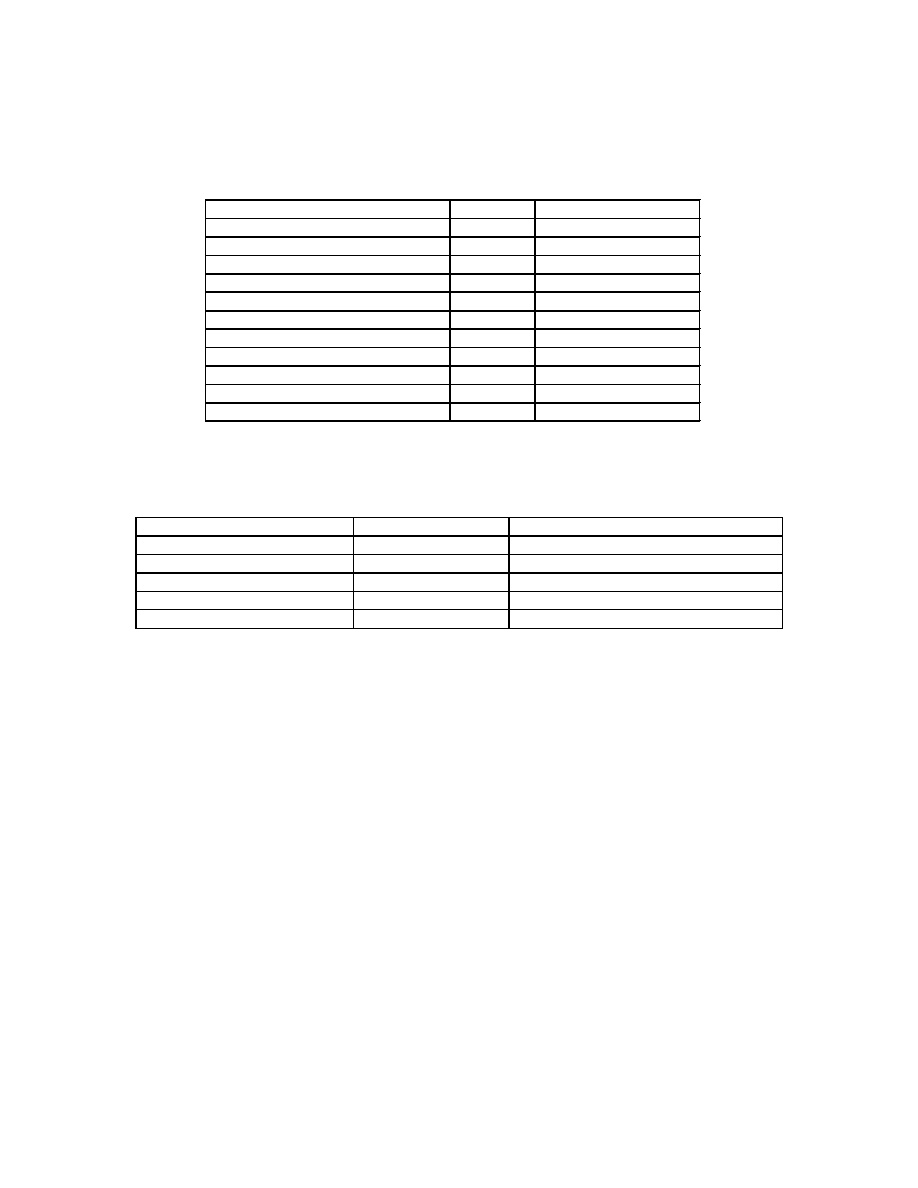
IRPLDIM1U Bill Of Materials
Lamp Type: T8/32W Line Input Voltage: 90 to 140 VAC/50/60Hz
Item Qty
Reference
Description
Manufacturer
Part
Number
1
1
BR1
Bridge Rectifier, 1A, 1000V
International Rectifier
DF10S
2
1
C4,CVDC
Capacitor, 0.47uF, SMT 1206
Panasonic
ECJ-3YB1E474K
3
1
C5
Capacitor, 0.68uF, SMT 1206
Panasonic
ECJ-3YB1E684K
4
1
C3
Capacitor, 0.01uF, SMT 1206
Panasonic
ECU-V1H103KBM
5
1
CVCO
Capacitor, 0.022uF, SMT 1206
Panasonic
ECU-V1H223KBM
6
1
C1
Capacitor, 0.33uF, 275VAC
Roederstein
F1772433-2200
7
2
CDC,C2
Capacitor, 0.1uF, 400VDC
Wima
MKP10
8 5 C7,CVCC1,C11,CMIN,
CDIM
Capacitor, 0.1uF, SMT 1206
Panasonic
ECJ-3VB1E104K
9
1
CPH
Capacitor, 0.39uF, SMT 1206
Panasonic
ECJ-3YB1E394K
10 1 CBUS
Capacitor,
10uF,
350VDC,105C
Panasonic
EEU-EB2V100
11 1 CVCC2
Capacitor,
4.7uF,
25VDC,105C
Panasonic
EEU-FC1H4R7
12
1
C10
Capacitor, 100pF, SMT 1206
Panasonic
ECU-V1H101JCH
13
1
C12
Capacitor, 1.5nF,1KV, SMT 1812
Johanson
102S43W152KV4
14 1 CRES
Capacitor,
8.2nF,
1600VDC
Panasonic
ECW-H16822JV
15 2 D1,D4
Diode,
1N4148,
SMT
DL35
Diodes
LL4148
16
2
D2,D3
Diode, SMT SMB
International Rectifier
10DF60
17
1
D5
Zener Diode, 20V, SMT DL35
Diodes
ZMM5250B-7
18
1
IC1
IC, Power Factor Controller
ST
L6561D
19
1
IC2
IC, Dimming Ballast Controller
International Rectifier
IR21592
20
1
L1
EMI Inductor, 1x10mH, 0.7A
Panasonic
ELF-15N007A
21
1
LPFC
PFC Inductor, 2.0mH, 2.0Apk
Coilcraft
Z9264B
22 1 LRES
Inductor,
2.0mH,
2.0Apk
Coilcraft
Z9265B
23 2 MHS,MLS
Transistor,
MOSFET
International
Rectifier IRF720
24 1 MPFC
Transistor,
MOSFET
International
Rectifier IRF730
25
1
R15
Resistor, 1K Ohm, SMT 1206
Panasonic
ERJ-8GEYJ102V
26
1
RFMIN
Resistor, 36K Ohm, SMT 1206
Panasonic
ERJ-8GEYJ363V
27
1
RDIM
Resistor, 10K Ohm, SMT 1206
Panasonic
ERJ-8GEYJ103V
28
1
RMAX
Resistor, 24K Ohm, SMT 1206
Panasonic
ERJ-8GEYJ243V
29
1
RMIN
Resistor, 27K Ohm, SMT 1206
Panasonic
ERJ-8GEYJ273V
30
1
RVDC
Resistor, 47K Ohm, SMT 1206
Panasonic
ERJ-8GEYJ473V
31
2
RIPH, R6
Resistor, 22K Ohm, SMT 1206
Panasonic
ERJ-8GEYJ223V
32
1
R12
Resistor, 13K Ohm, SMT 1206
Panasonic
ERJ-8GEYJ133V
33
2
R1,R2
Resistor, 680K Ohm, SMT 1206
Panasonic
ERJ-8GEYJ684V
34
1
R3
Resistor, 7.5K Ohm, SMT 1206
Panasonic
ERJ-8GEYJ752V
35 1 R4
Resistor,
330K
Ohm
Yageo
CFR-25JR-330K
36 1 R5
Resistor,
1M
Ohm
Yageo
CFR-25JR-1M0
37
3
R7,R13,R14
Resistor, 22 Ohm, SMT 1206
Panasonic
ERJ-8GEYJ220V
38
1
F1
Resistor, 0.5 Ohm, ½ Watt
Dale
CW-1/2
39
2
R9,R16
Resistor, 100K Ohm, SMT 1206
Panasonic
ERJ-8GEYJ104V
40
2
R10,R11
Resistor, 820K Ohm, SMT 1206
Panasonic
ERJ-8GEYJ824V
41
1
R17
Resistor, 1M Ohm, SMT 1206
Panasonic
ERJ-8GEYJ105V
42
1
RS
Resistor, 0.5 Ohm, ¼ Watt
Yageo
CFR-25JR-R5
43
1
RCS
Resistor, 0.57Ohm, ¼ Watt
Yageo
CFR-25JR-R57
44
1
RDC
Resistor, 100K Ohm, ¼ Watt
Yageo
CFR-25JR-100K
45 1 X1
Connector,
5
terminal
Wago
46 1 X2
Connector,
4
terminal
Wago
236-404
47 1 J1
Jumper
48 1 CY
Y
Capacitor
Roederstein
WYO222MCMBFOK
49 1 RV1
Varistor
Panasonic
ERZ-VO5D471
50
2
RLM1,RLM2
Resistor, 10 Ohm, SMT 1206
Panasonic
ERJ-8GEYJ100V
Total 66