www.irf.com
1
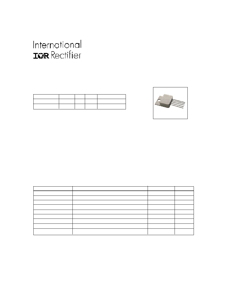
Product Summary
Part Number Dropout I
O
Vin Package
OMR9604SC 0.4 V 3.0A 3.3V MO-078AA
OMR9604SF 0.4 V 3.0A 3.3V 8-Lead Flatpack
Features:
n
Total dose and low dose capabilitiy to 1M
Rad(Si) allows use in space applications
n
Ultra low dropout of 0.4 volt significantly
reduces power consumption
n
Low noise, higher efficiency
n
Remote shutdown permits power
sequencing to be easily implemented
n
Hermetic MO-078AA (TO-258AA) and 8-
lead flat pack ensure higher reliability
n
K-level screened
The OMR9604 is a radiation hardened, ultra low dropout
adjustable linear regulator designed specifically for space
applications. This product has been characterized to a
total ionizing dose of 1 M Rad (Si) per MIL-STD-883, Method
1019, Condition A at both high and low dose rates under
biased and unbiased conditions to account for ELDRS
effects in bipolar devices. The ultra low dropout voltage of
0.4V @ 3A makes the part particularly useful for applica-
tions requiring low noise and higher efficiency.
MO-078AA
Absolute Maximum Ratings
Symbol
Parameter
Value
Units
Io
Output Current
3.5
A
Vin
Input Voltage
+7.0
V
Vout
Output Voltage Range
+1.26 to +3.2
V
P
TOT
Power Dissipation TC=25
o
C
19
W
RTHJC
Thermal Resistance, Junction to Case (MO-078AA)
6.5
�C/W
R
THJC
Thermal Resistance, Junction to Case (8 lead flatpack)
6.5
�C/W
TJ
Operating Junction
-55 to +125
o
C
TSTG
Storage Temperature Range
-65 to +150
o
C
T
L
Lead Temperature
300
o
C
PD-94478A
8/20/02
1 M Rad(Si) Ultra Low Dropout
OMR9604SC
Positive Adjustable Linear Regulator
OMR9604SF
Hermetic Package
+ 3.3Vin at 3.0A
2
www.irf.com
OMR9604SC, OMR9604SF
Electrical Characteristics
@ T
A
= 25�C (Unless Otherwise Specified)
Electrical Characteristics
T
A
= -55 to +125�C
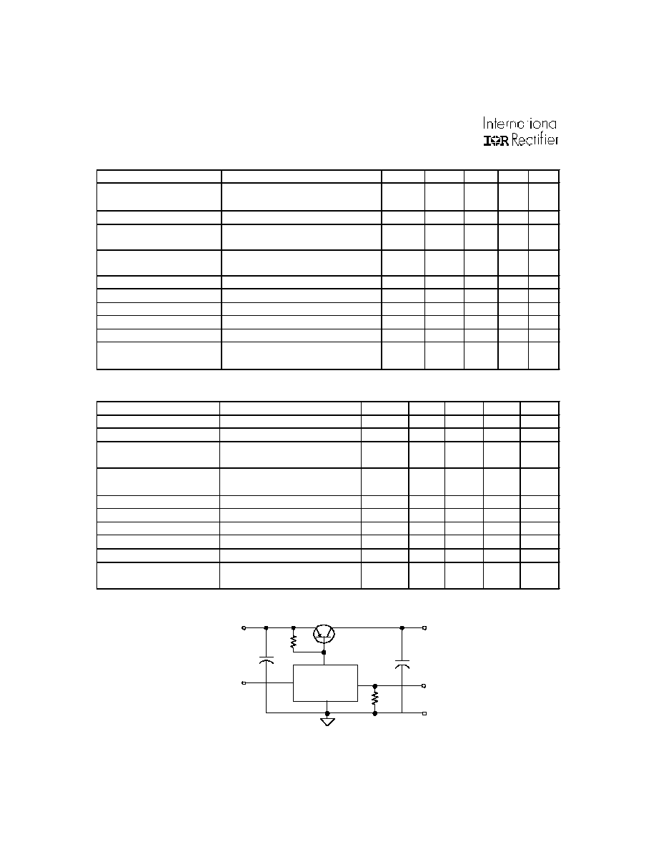
S h u t d o w n
V i n
V o u t
G r o u n d
Drive
G n d
A d j u s t
Parameter
Conditions
Symbol
Min.
Typ.
Max Unit
Input Voltage Range-
Operating
Io= 3.0A
Vin
2.9
6.5
V
Reference Voltage
Vref
1.252
1.265 1.278
V
3.13
Vin
3.46, Io= 3.0A
-100
+100 mV
2.9
Vin
3.8, Io= 50mA
-5
+5
mV
Vin= 3.3V
10ma
Iout
3.0A
Dropout Voltage
Io= 3.0A. Vout= 2.5V
Vdrop
0.4
V
Current Limit
Vin= 3.3V, Overcurrent Latchup
Ilatch
3.0
A
Ripple Rejection
F= 120 Hz., Vout= Vref
65
dB
Shutdown Source Current
Vshdn= 5V
Ishdn
200
uA
Shutdown Pin Threshold
Isource= 200uA
Vshdn
1.0
1.6
V
Vin= 3.3V, Io= 50mA,
Shdn= +5.0V
Line Regulation
Vline
Load Regulation
Vload
-20
+20
mV
Output Voltage at
Shutdown
Vout
(shdn)
-0.1
+0.1
V
Simplified Schematic
Parameter
Conditions
Symbol
Min.
Typ.
Max
Unit
Input Voltage Range-
Io= 3.0A
Vin
2.9
6.5
V
Reference Voltage
Vref
1.225
1.265
1.305
V
3.13
Vin
3.46, Io= 3.0A
-150
+150
mV
2.9
Vin
3.8, Io= 50mA
-150
+150
mV
Vin= 3.3V
10ma
Iout
3.0A
Dropout Voltage
Io= 3.0A. Vout= 2.5V
Vdrop
0.4
V
Current Limit
Vin= 3.3V, Overcurrent Latchup
Ilatch
3.0
A
Ripple Rejection
F= 120 Hz., Vout= Vref
65
dB
Shutdown Source Current
Vshdn= 5V
Ishdn
200
uA
Shutdown Pin Threshold
Isource= 200uA
Vshdn
1.0
1.6
V
Vin= 3.3V, Io= 50mA,
Shdn= +5.0V
Line Regulation
Vline
Load Regulation
Vload
-150
+150
mV
Output Voltage at Shutdown
Vout
(shdn)
-0.1
0.1
V

www.irf.com
3
OMR9604SC, OMR9604SF
OMR9604 Ripple Rejection vs. Frequency
0
20
40
60
80
100
120
100
1,000
10,000
100,000
1,000,000
Frequency (Hz)
(db)
3A
1.5A
.75A
.50A
O M R 9 6 0 4
Vout
A D J
V i n
S H D N
GND
100uF 16V
Tantalum
1.0uF
Ceramic
X7R
220uF 6.3V
Tantalum
Adjust
Resistor
R 1
Vout =Vref x (1+R1/1000)
In order to maintain regulation and stability speci-
fied additional input and output bulk capacitors are
recommended. Capacitors recommended above
should be low ESR tantalums with tolerances of +/-
20% max. Internal to the product are a 4.7uF input
capacitor and a 4.7uF output capacitor in parallel
with a 0.33uF ceramic capacitor.
Shutdown: The regulator can be shutdown by apply-
ing a voltage >1.6V to pin 4. The regulator will restart
when the SHDN pin is pulled below the shutdown
threshold of 1.0V. If remote shutdown is not required,
pin 4 shold be connected to GND to insure a safe
"off" state.
4
www.irf.com
OMR9604SC, OMR9604SF
1 2 3 4 5
Base
Base: GLIDCOP
Pins: Copper core, Alloy 52
Seals: Glass
Pin Connections
Terminal Description
1
Vin
2
GND
3
Vout
4
Shutdown
5
Adjust
Base: 1010-1018 C.R.S.
Pins: #52 Alloy, Copper Cored
Seals: Glass � 9013 or Equiv.
Finish: 100-250 Microinches
Electroless Nickel Over 50-250
Microinches Electrolytic Nickel.
Pin Connections
Terminal Description
1,2
GND
3
Shutdown
4
Adjust
5,6
Vout
7,8
Vin
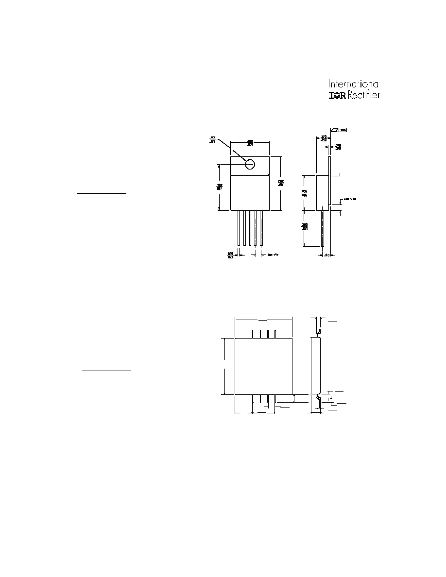
Mechanical Outline MO-078AA
Mechanical Outline 8-Lead Flat Pack
0.755
0.745
0.755
0.745
0.225
0.305
0.295
0.105
0.095
0.020
0.016
0.180
0.165
8X
0.040
0.065
0.040
0.065
8X 0.080
0.070
8x
0.110
0.150
1 2 3 4
8 7 6 5

www.irf.com
5
OMR9604SC, OMR9604SF
Part Number Nomenclature
OM
R
9604
X
X X
Omnirel Radiation
Device
S=Isolated Package Screening
Hardened/Tolerant
N=Non-Isolated
Part Number
Package Description
Screening
OMR9604SCP
MO-078AA 5 - Lead
100% Final Electrical
OMR9604SCK
MO-078AA 5 - Lead
Class K per MIL-PRF-38534
OMR9604SFP
8 -Lead Flat Pack
100% Final Electrical
OMR9604SFK
8 -Lead Flat Pack
Class K per MIL-PRF-38534
TEST/INSPECTION
SCREENING LEVEL
MIL-STD-883
Class K
Method
(Space Level)
Pre Seal Burn-In
Optional
1030
Nondestructive Bond Pull
100%
2023
Internal Visual
100%
2017
Temperature Cycle
100%
1010
Constant Acceleration
100%
2001
Mechanical Shock
100%
2002
PIND
100%
2020
Pre Burn-In Electrical
100%
Burn-In
100%
1015
Final Electrical
100%
Seal
100%
1014
Radiographic
100%
2012
External Visual
100%
2009
MIL-PRF-38534 Screening Requirements
WORLD HEADQUARTERS: 233 Kansas St., El Segundo, California 90245, Tel: (310) 2527105
IR LEOMINSTER: 205 Crawford St., Leominster, Massachusetts 01453, Tel: (978) 5345776
Data and specifications subject to change without notice. 8/2002