Data Sheet No. PD10054-B
Series PVI-N
Photovoltaic Isolator
Single and Dual Channel
5-10 Volt Output
General Description
The PVI Series Photovoltaic Isolator generates an
electrically isolated DC voltage upon receipt of a DC
input signal. It is capable of directly driving gates of
power MOSFETs or IGBTs. It utilizes a monolithic
integrated circuit photovoltaic generator of novel
construction as its output. The output is controlled by
radiation from a GaAlAs light emitting diode (LED),
which is optically isolated from the photovoltaic
generator.
The PVI Series is ideally suited for applications
requiring high-current and/or high-voltage switching
with optical isolation between the low-level driving
circuitry and high-energy or high-voltage load circuits.
It can be used for directly driving gates of power
MOSFETs. The dual-channel device allows its outputs
to drive independent discrete power MOSFETs, or be
connected in parallel or in series to provide higher
current drive for power MOSFETs or higher voltage
drive for IGBTs. The PVI Series Photovoltaic isolators
employ fast turn-off circuitry.
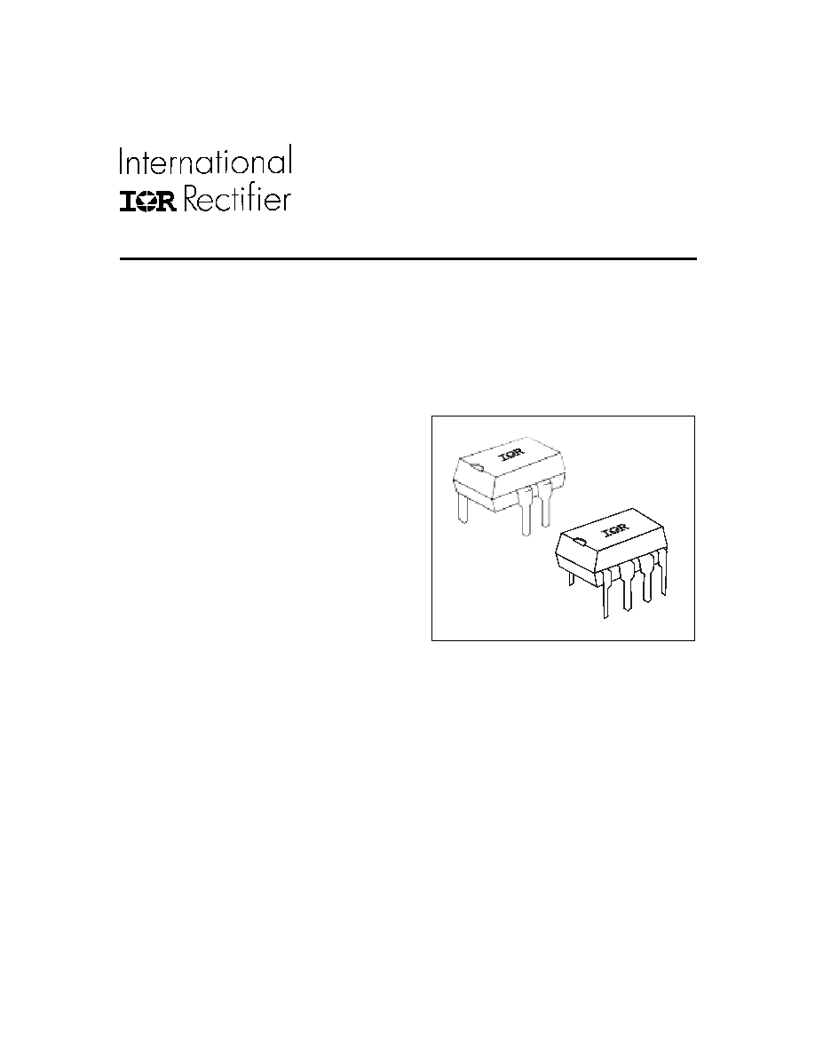
These PVI Series Photovoltaic Isolators are packaged
in 8-pin, molded DIP packages and available with
either thru-hole or surface-mount ("gull-wing") leads,
in plastic shipping tubes.
Applications
!
Load Distribution
!
Industrial Controls
!
Current-to-Voltage Conversion
!
Custom Solid-State Relay
Features
!
Isolated Voltage Source
!
Monolithic Construction
!
Up to 8
�
A Output
!
Single or Dual Output
!
Solid-State Reliability
Part Identification
PVI1050N
PVI5050N
thru-hole
PVI5080N
PVI1050NS
PVI5050NS
PVI5080NS
surface-mount
(gull-wing)
www.irf.com
1

Series PVI-N
2
www.irf.com
Electrical Specifications (-40
�
C
T
A
+85
�
C unless otherwise specified
)
OUTPUT CHARACTERISTICS
PVI Series
Units
Maximum Forward Voltage @ 10�A
8.0 per channel
V
(DC)
Maxiumum Reverse Current @ -10VDC
10
�A
(DC)
INPUT CHARACTERISTICS
PVI Series
Units
Input Current Range
(see figure 4)
2.0 to 50
mA (DC)
Maximum Forward Voltage Drop @ 10mA, 25�C
(see figure 5)
1.4
V (DC)
Maximum Reverse Voltage
7.0
V(DC)
Maximum Reverse Current @ -7.0V (DC), 25�C
100
�A(DC)
Maximum Pulsed Input Current @ 25�C
(see figure 6)
1.0
A(peak)
GENERAL CHARACTERISTICS
PVI5050N
/
5080N PVI1050N
Units
Min. Dielectric Strength, Input-Output
4000
2500
V
RMS
Min. Dielectric Strength, Output-to-Output
1200
V
DC
Min. Insulation Resistance, Input-to-Output
@TA=+25�C, 50%RH, 100VDC
Max. Pin Soldering Temperature (10 seconds max.) +260
�C
Ambient Temperature Range: Operating
-40 to +85
�C
Storage
-40 to +125
�C
10
12
COUPLED CHARACTERISTICS
PVI5050N
PVI5080N
PVI1050N
Units
Minimum Open Circuit Voltage
@ ILED = 10mA, 25�C, RL =
>
10M
5.0
5.0/channel
V (DC)
(see figures 1 to 2)
10 series
Minimum Short Circuit Current
@ ILED = 10mA, 25�C (see figures 1 to 2)
5.0
8.0
5.0 /channel
�A (DC)
10 parallel
Maximum Capacitance (Input/Output)
1.0
2.0
pF
Maximum Ton Time @ ILED=10mA, CLOAD=10pF (See Figure7)
RL>20M
300
�S
RL=10M
160
�S
RL=4.7M
90
�S
Maximum Toff Time @ ILED=10mA, CLOAD=10pF (See Figure7) 220
�S
International Rectifier does not recommend the use of this product in aerospace, avionics, military or life support applications.
Users of this International Rectifier product in such applications assume all risks of such use and indemnify International
Rectifier against all damages resulting from such use.

Series PVI-N
www.irf.com
3
Output V
oltage (VDC)
Figure 1. PVI5050N, PVI1050N Typical Output Characteristics
Input Current (mA)
Output Short Circuit Current (�A)
Output V
oltage (VDC)
Figure 2. PVI15080N Typical Output Characteristics
Input Current (mA)
Output Short Circuit Current (�A)
0
1
2
3
4
5
6
7
8
0
2
4
6
8
10
12
14
16
18
20
0
5
10
15
20
25
30
35
40
0
1
2
3
4
5
6
7
8
0
2
4
6
8
10
12
14
16
18
20
0
5
10
15
20
25
30
35
40
Open Circuit Voltage
R
L
=10M
R
L
=4.7M
R
L
=2.2M
R
L
=1M
Short Circuit Current
Open Circuit Voltage
R
L
=10M
R
L
=4.7M
R
L
=2.2M
R
L
=1M
Short Circuit Current
Figure 4. Input Current Derating
Ambient Temperature (�C)
Allowable Input Current (mA)
Figure 5. Input Characteristics
Duty Cycle
Allowable Input Pulse Current (mA)
Figure 6. Input Pulse Capability
Normalized Output
Figure 3. Typical Variation of Output
Forced Air Temperature (�C)
0.2
0.4
0.6
0.8
1.0
1.2
1.4
1.6
1.8
-40 -30 -20 -10 0
10 20 30 40 50 60 70 80 90 100
Short Circuit Current (Isc)
Output Voltage (Voc)
LED Forward Voltage Drop (VDC)
Input Current (mA)
CAUTION: Provide current limiting
so that 50mA maximum steady-
state control current is not
exceeded.

Series PVI-N
4
www.irf.com
Application Note:
The outputs of the PVI1050N (pins 5-6 and 7-8) may be placed in series connection to produce a 10-volt output
with a 5�A minimum short circuit current. Alternatively, the two ouptut of the PVI1050 may be connected in paral-
lel to produce a 5.0-volt ouput with a 10�A minimum short circuit current.
The two outputs of the PVI1050N may be applied separately with a maximum 1200VDC between the outputs.
Input-to-output isolation to either output is 2500V (RMS).
Figure 7. Typical Response Time
Response T
i
me (�s)
Load Capacitance (pF)
Wiring Diagram
10
100
1000
10000
0
200
400
600
800
1000
Ton
R
L
=10M
R
L
=4.7M
R
L
=2.2M
Toff
Anode
(+) 1
Cathode
Anode
Cathode
(-) 2
(+) 3
(-) 4
(-) 8
(+) 7
(-) 6
(+) 5
PVI1050N
Anode
(+) 2
Cathode
(-) 3
(+) 5
(-) 8
DC
PVI5050N
PVI5080N
