 | ÐлекÑÑоннÑй компоненÑ: SD700C | СкаÑаÑÑ:  PDF PDF  ZIP ZIP |
Äîêóìåíòàöèÿ è îïèñàíèÿ www.docs.chipfind.ru
SD700C..L SERIES
STANDARD RECOVERY DIODES
Hockey Puk Version
700A
Bulletin I2096/A
Features
Wide current range
High voltage ratings up to 4500V
High surge current capabilities
Diffused junction
Hockey Puk version
Case style DO-200AB (B-PUK)
Typical Applications
Converters
Power supplies
High power drives
Auxiliary system supplies for traction applications
Major Ratings and Characteristics
I
F(AV)
700
A
@ T
hs
55
°C
I
F(RMS)
1310
A
@ T
hs
25
°C
I
FSM
@
50Hz
7500
A
@ 60Hz
7850
A
I
2
t
@
50Hz
281
KA
2
s
@ 60Hz
257
KA
2
s
V
RRM
range
3000 to 4500
V
T
J
- 40 to 150
°C
Parameters
SD700C..L
Units
case style DO-200AB (B-PUK)
Next Data Sheet
Index
Previous Datasheet
To Order
SD700C..L Series
Voltage
V
RRM
, maximum repetitive
V
RSM
, maximum non-
I
RRM
max.
Type number
Code
peak reverse voltage
repetitive peak rev. voltage
@ T
J
= T
J
max.
V
V
mA
30
3000
3100
36
3600
3700
40
4000
4100
45
4500
4600
ELECTRICAL SPECIFICATIONS
Voltage Ratings
SD700C..L
50
I
F(AV)
Max. average forward current
700 (345)
A
180° conduction, half sine wave
@ Heatsink temperature
55 (85)
°C
Double side (single side) cooled
I
F(RMS)
Max. RMS forward current
1310
A
@ 25°C heatsink temperature double side cooled
I
FSM
Max. peak, one-cycle forward,
7500
t = 10ms
No voltage
non-repetitive surge current
7850
t = 8.3ms
reapplied
6310
t = 10ms
50% V
RRM
6600
t = 8.3ms
reapplied
Sinusoidal halfwave,
I
2
t
Maximum I
2
t for fusing
281
t = 10ms
No voltage
Initial T
J
= T
J
max.
257
t = 8.3ms
reapplied
199
t = 10ms
50% V
RRM
182
t = 8.3ms
reapplied
I
2
t
Maximum I
2
t for fusing
2810
KA
2
s
t = 0.1 to 10ms, no voltage reapplied
V
F(TO)1
Low level value of threshold
voltage
V
F(TO)2
High level value of threshold
voltage
r
f
1
Low level value of forward
slope resistance
r
f
2
High level value of forward
slope resistance
V
FM
Max. forward voltage drop
1.66
V
I
pk
= 1000A, T
J
= T
J
max, t
p
= 10ms sinusoidal wave
A
KA
2
s
0.88
(16.7% x
x I
F(AV)
< I <
x I
F(AV)
), T
J
= T
J
max.
Parameter
SD700C..L
Units
Conditions
Forward Conduction
V
m
0.78
(16.7% x
x I
F(AV)
< I <
x I
F(AV)
), T
J
= T
J
max.
0.99
(I >
x I
F(AV)
),T
J
= T
J
max.
0.73
(I >
x I
F(AV)
),T
J
= T
J
max.
Next Data Sheet
Index
Previous Datasheet
To Order
SD700C..L Series
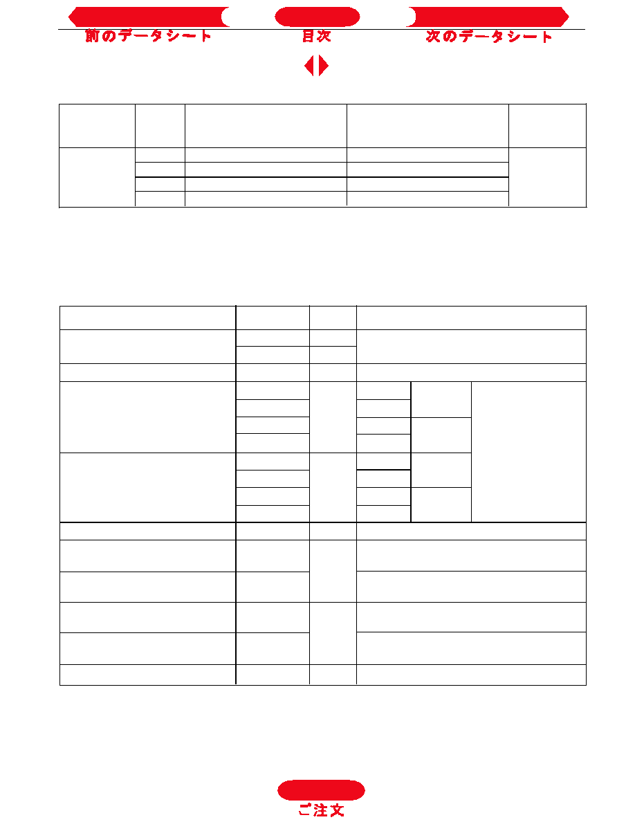
Fig. 4 - Current Ratings Characteristics
Fig. 6 - Forward Power Loss Characteristics
Fig. 7 - Maximum Non-Repetitive Surge Current
Fig. 8 - Maximum Non-Repetitive Surge Current
Fig. 3 - Current Ratings Characteristics
Fig. 5 - Forward Power Loss Characteristics
To Order
Next Data Sheet
Index
Previous Datasheet
SD700C..L Series
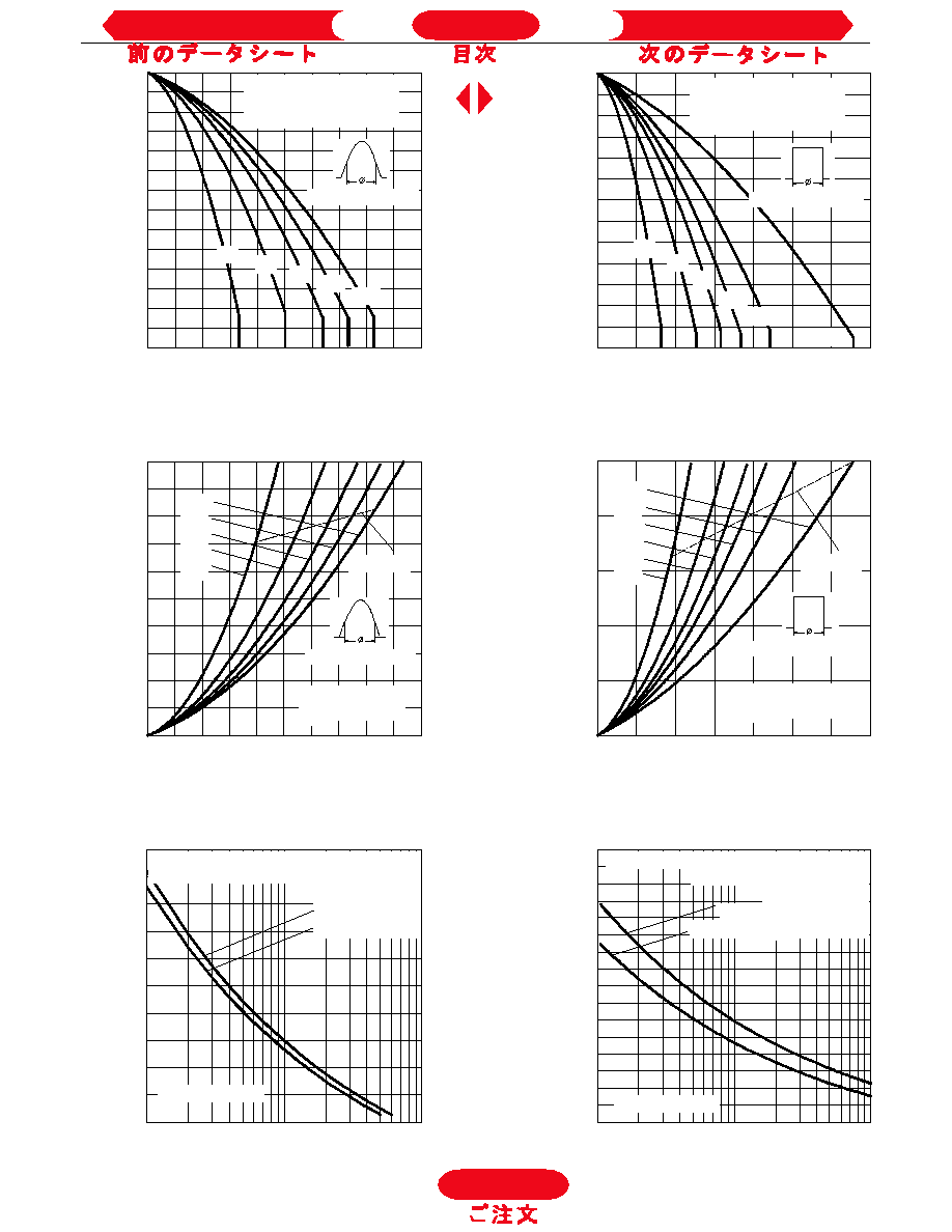
Fig. 10 - Thermal Impedance Z
thJ-hs
Characteristics
Fig. 9 - Forward Voltage Drop Characteristics
To Order
Next Data Sheet
Index
Previous Datasheet
SD700C..L Series
R
thJ-hs
Conduction
(The following table shows the increment of thermal resistence R
thJ-hs
when devices operate at different conduction angles than DC)
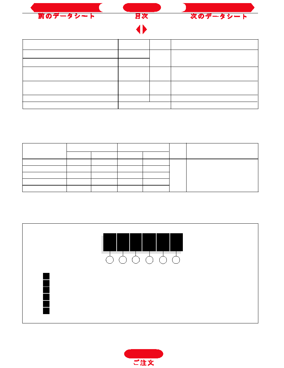
Ordering Information Table
1
-
Diode
2
-
Essential part number
3
-
0 = Standard recovery
4
-
C = Ceramic Puk
5
-
Voltage code: code x 100 = V
RRM
(see Voltage Ratings Table)
6
-
L = Puk Case DO-200AB (B-PUK)
1
2
3
4
5
6
Device Code
SD
70
0
C
45
L
Sinusoidal conduction
Rectangular conduction
Conduction angle
Units
Conditions
Single Side Double Side
Single Side Double Side
180°
0.011
0.011
0.008
0.008
120°
0.014
0.015
0.014
0.014
90°
0.018
0.018
0.019
0.019
K/W
T
J
= T
J
max.
60°
0.026
0.026
0.027
0.028
30°
0.045
0.046
0.046
0.046
T
J
Max. junction operating temperature range
-40 to 150
T
stg
Max. storage temperature range
-55 to 200
R
thJ-hs
Max. thermal resistance, junction
0.11
DC operation single side cooled
to heatsink
0.05
DC operation double side cooled
F
Mounting force, ± 10%
9800
N
(1000)
(Kg)
wt
Approximate weight
250
g
Case style
DO-200AB(B-PUK)
See Outline Table
Parameter
SD700C..L
Units
Conditions
Thermal and Mechanical Specifications
°C
K/W
To Order
Next Data Sheet
Index
Previous Datasheet